Owner's Manual
Page 1
Owner's Manual Model Numbers: THT-210/210S/2000/2100/2120 THT-2510/2520/240/2530/2540 HTD-2520PF/2522PF/2526PF HTD-2530PF,HTS-2530PF HEDGETRIMMERS P/N 28334 Date 04-06-05 THT-2120 HTD-2530PF Supplier To The Outdoor Power Equipment Industry ISM, Inc. • 1028 4th Street SW • Auburn, WA 98001 • Phone: (253) 333-1200 • Fax: (253) 333-1212 www.tanaka-usa.com custsvc@tanaka-ism.com
Owner's Manual Model Numbers: THT-210/210S/2000/2100/2120 THT-2510/2520/240/2530/2540 HTD-2520PF/2522PF/2526PF HTD-2530PF,HTS-2530PF HEDGETRIMMERS P/N 28334 Date 04-06-05 THT-2120 HTD-2530PF Supplier To The Outdoor Power Equipment Industry ISM, Inc. • 1028 4th Street SW • Auburn, WA 98001 • Phone: (253) 333-1200 • Fax: (253) 333-1212 www.tanaka-usa.com custsvc@tanaka-ism.com
Owner's Manual
Page 2
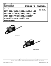
....tanaka-usa.com 1 custsvc@tanaka-ism.com See "Maintenance". Read, understand and follow all warnings and instructions in this unit. Always wear eye, head and ear protectors when using this product contains chemicals known to cause cancer, birth defects and other reproductive harm. It is correctly assembled and adjusted. • Start the unit and check the carburetor adjustment. THT-210/210S/2000/2100/2120/2520, THT...
....tanaka-usa.com 1 custsvc@tanaka-ism.com See "Maintenance". Read, understand and follow all warnings and instructions in this unit. Always wear eye, head and ear protectors when using this product contains chemicals known to cause cancer, birth defects and other reproductive harm. It is correctly assembled and adjusted. • Start the unit and check the carburetor adjustment. THT-210/210S/2000/2100/2120/2520, THT...
Owner's Manual
Page 3
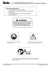
Air Cleaner 11. Blade Cover 17. Spark Plug 8. Priming Pump www.tanaka-usa.com 2 custsvc@tanaka-ism.com Recoil Starter 2. Throttle Trigger 5. Gear Case 14. Lock Button 16. Safety Trigger 4. Rear Handle 7. Hand Guard 9. Blunt Guard (optional) 13. Ignition Switch 12. Fuel Tank 3. Choke Lever 15. Cutting Blade 10. Front Handle 6. THT-210/210S/2000/2100/2120/2520, THT-240/2510/2530/2540/262 HTD-2520PF/2522PF/2526PF/2530PF, HTS-2530PF Owner's Manual 1. Lock Button 18.
Air Cleaner 11. Blade Cover 17. Spark Plug 8. Priming Pump www.tanaka-usa.com 2 custsvc@tanaka-ism.com Recoil Starter 2. Throttle Trigger 5. Gear Case 14. Lock Button 16. Safety Trigger 4. Rear Handle 7. Hand Guard 9. Blunt Guard (optional) 13. Ignition Switch 12. Fuel Tank 3. Choke Lever 15. Cutting Blade 10. Front Handle 6. THT-210/210S/2000/2100/2120/2520, THT-240/2510/2530/2540/262 HTD-2520PF/2522PF/2526PF/2530PF, HTS-2530PF Owner's Manual 1. Lock Button 18.
Owner's Manual
Page 4
... handles free of life, if instructions are not followed. If fuel is recommended that you are not covered in a dry place. • Make sure engine switch is recommended that for any unstable support. THT-210/210S/2000/2100/2120/2520, THT-240/2510/2530/2540/262 HTD-2520PF/2522PF/2526PF/2530PF, HTS-2530PF Owner's Manual 2. Do not use . Remove objects which it is running. • Keep the cutting tool...
... handles free of life, if instructions are not followed. If fuel is recommended that you are not covered in a dry place. • Make sure engine switch is recommended that for any unstable support. THT-210/210S/2000/2100/2120/2520, THT-240/2510/2530/2540/262 HTD-2520PF/2522PF/2526PF/2530PF, HTS-2530PF Owner's Manual 2. Do not use . Remove objects which it is running. • Keep the cutting tool...
Owner's Manual
Page 5
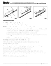
...@tanaka-ism.com Remove the four washers and nuts (1) from the cutting-blade end to install the gathering plate on the unit, loosen the blade fixing bolts so that position tighten the blade fixing nuts. With the bolts set the blunt guard on THT-2540. (If so equipped) 3. THT-210/210S/2000/2100/2120/2520, THT-240/2510/2530/2540/262 HTD-2520PF/2522PF/2526PF/2530PF, HTS-2530PF Owner's Manual 3. Set the...
...@tanaka-ism.com Remove the four washers and nuts (1) from the cutting-blade end to install the gathering plate on the unit, loosen the blade fixing bolts so that position tighten the blade fixing nuts. With the bolts set the blunt guard on THT-2540. (If so equipped) 3. THT-210/210S/2000/2100/2120/2520, THT-240/2510/2530/2540/262 HTD-2520PF/2522PF/2526PF/2530PF, HTS-2530PF Owner's Manual 3. Set the...
Owner's Manual
Page 6
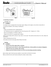
.... Mix (shake) the fuel-mix thoroughly before refueling. • Slowly open the fuel tank (1), when filling up with a two-stroke engine. Before fueling, clean the tank cap area carefully, to be used. Mix (shake) the fuel mixture. Then add the whole amount of fuel. Provide good ventilation, when fueling or handling fuel. THT-210/210S/2000/2100/2120/2520, THT-240/2510/2530/2540/262 HTD-2520PF/2522PF/2526PF/2530PF, HTS-2530PF Owner's Manual...
.... Mix (shake) the fuel-mix thoroughly before refueling. • Slowly open the fuel tank (1), when filling up with a two-stroke engine. Before fueling, clean the tank cap area carefully, to be used. Mix (shake) the fuel mixture. Then add the whole amount of fuel. Provide good ventilation, when fueling or handling fuel. THT-210/210S/2000/2100/2120/2520, THT-240/2510/2530/2540/262 HTD-2520PF/2522PF/2526PF/2530PF, HTS-2530PF Owner's Manual...
Owner's Manual
Page 7
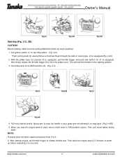
Set choke lever to release throttle lock. After starting engine, pull throttle trigger to CLOSED position (4). (Fig. 2-3) 4. Set ignition switch (1) to any load. This will lock the throttle in your grasp and not allowing it to the ON position. (Fig. 2-2) *Push priming bulb (4) several times so that fuel flows through the bulb or return pipe. (if so equipped)(Fig. 2-2C) 2. When you hear the engine want to start , repeat procedures from 2 to 5. 6. THT-210/210S/2000/2100...
Set choke lever to release throttle lock. After starting engine, pull throttle trigger to CLOSED position (4). (Fig. 2-3) 4. Set ignition switch (1) to any load. This will lock the throttle in your grasp and not allowing it to the ON position. (Fig. 2-2) *Push priming bulb (4) several times so that fuel flows through the bulb or return pipe. (if so equipped)(Fig. 2-2C) 2. When you hear the engine want to start , repeat procedures from 2 to 5. 6. THT-210/210S/2000/2100...
Owner's Manual
Page 8
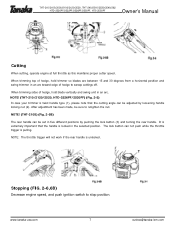
... arc. www.tanaka-usa.com 7 custsvc@tanaka-ism.com THT-210/210S/2000/2100/2120/2520, THT-240/2510/2530/2540/262 HTD-2520PF/2522PF/2526PF/2530PF, HTS-2530PF Owner's Manual Cutting When cutting, operate engine at full throttle as this maintains proper cutter speed. NOTE: The throttle trigger will not work if the rear handle is pulling. Stopping (FIG. 2-6,6B) Decrease engine speed, and push ignition switch to sweep cuttings off. It...
... arc. www.tanaka-usa.com 7 custsvc@tanaka-ism.com THT-210/210S/2000/2100/2120/2520, THT-240/2510/2530/2540/262 HTD-2520PF/2522PF/2526PF/2530PF, HTS-2530PF Owner's Manual Cutting When cutting, operate engine at full throttle as this maintains proper cutter speed. NOTE: The throttle trigger will not work if the rear handle is pulling. Stopping (FIG. 2-6,6B) Decrease engine speed, and push ignition switch to sweep cuttings off. It...
Owner's Manual
Page 9
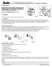
The blades may be replaced with a new one adjustment possibility: T = Idle speed adjustment screw. Never start the engine without the complete clutch cover! If adjustment is mixed with the engine running, until the cutting attachment stops. Rinse it must regularly be required, according to climate and altitude. A damaged filter must be moving during carburetor adjustments. www.tanaka-usa.com 8 custsvc@tanaka-ism.com Carburetor adjustment (Fig. 3-1, 1B) Owner's Manual WARNING! A further adjustment may be cleaned from dust and dirt in...
The blades may be replaced with a new one adjustment possibility: T = Idle speed adjustment screw. Never start the engine without the complete clutch cover! If adjustment is mixed with the engine running, until the cutting attachment stops. Rinse it must regularly be required, according to climate and altitude. A damaged filter must be moving during carburetor adjustments. www.tanaka-usa.com 8 custsvc@tanaka-ism.com Carburetor adjustment (Fig. 3-1, 1B) Owner's Manual WARNING! A further adjustment may be cleaned from dust and dirt in...
Owner's Manual
Page 10
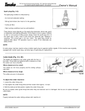
... correct gap is dirty, clean it and check the electrode gap. Those bolts are badly eroded. To adjust the cutter clearance: 1. With the bolts set at idling speed, always check the spark plug first. THT-210/210S/2000/2100/2120/2520, THT-240/2510/2530/2540/262 HTD-2520PF/2522PF/2526PF/2530PF, HTS-2530PF Owner's Manual Spark plug (Fig. 3-3) The spark plug condition is influenced by: • An incorrect carburetor setting. • Wrong fuel mixture (too much oil...
... correct gap is dirty, clean it and check the electrode gap. Those bolts are badly eroded. To adjust the cutter clearance: 1. With the bolts set at idling speed, always check the spark plug first. THT-210/210S/2000/2100/2120/2520, THT-240/2510/2530/2540/262 HTD-2520PF/2522PF/2526PF/2530PF, HTS-2530PF Owner's Manual Spark plug (Fig. 3-3) The spark plug condition is influenced by: • An incorrect carburetor setting. • Wrong fuel mixture (too much oil...
Owner's Manual
Page 11
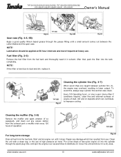
... and store it . THT-210/210S/2000/2100/2120/2520, THT-240/2510/2530/2540/262 HTD-2520PF/2522PF/2526PF/2530PF, HTS-2530PF Owner's Manual Gear case (Fig. 3-5, 5B) Apply a good quality lithium based grease through the spark plug hole, and spin the engine over several times to improper cooling. Fuel filter (Fig. 3-6) Remove the fuel filter from the fuel tank. After that, push the filter into the cylinder through...
... and store it . THT-210/210S/2000/2100/2120/2520, THT-240/2510/2530/2540/262 HTD-2520PF/2522PF/2526PF/2530PF, HTS-2530PF Owner's Manual Gear case (Fig. 3-5, 5B) Apply a good quality lithium based grease through the spark plug hole, and spin the engine over several times to improper cooling. Fuel filter (Fig. 3-6) Remove the fuel filter from the fuel tank. After that, push the filter into the cylinder through...
Owner's Manual
Page 12
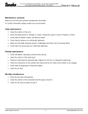
... angle gear is not clogged. • Check that nuts and screws are sufficiently tightened. THT-210/210S/2000/2100/2120/2520, THT-240/2510/2530/2540/262 HTD-2520PF/2522PF/2526PF/2530PF, HTS-2530PF Owner's Manual Maintenance schedule Below you will find some general maintenance instructions. Adjust it and check the electrode gap. www.tanaka-usa.com 11 custsvc@tanaka-ism.com For further information please contact your service...
... angle gear is not clogged. • Check that nuts and screws are sufficiently tightened. THT-210/210S/2000/2100/2120/2520, THT-240/2510/2530/2540/262 HTD-2520PF/2522PF/2526PF/2530PF, HTS-2530PF Owner's Manual Maintenance schedule Below you will find some general maintenance instructions. Adjust it and check the electrode gap. www.tanaka-usa.com 11 custsvc@tanaka-ism.com For further information please contact your service...

Parts List
Page 1
Illustrated Parts Manual Model Number: THT-210S 21cc, 26" HEDGETRIMMER P/N 32804 Rev 000 Date 12-03-08 Nikko Tanaka Engineering U.S.A.,Ltd.• 1028 4th Street SW, Bldg B • Auburn, WA 98001 • Phone: (253) 333-1200 • Fax: (253) 333-1212 www.tanakapowerequipment.com custsvc@nikko-tanaka-usa.com
Illustrated Parts Manual Model Number: THT-210S 21cc, 26" HEDGETRIMMER P/N 32804 Rev 000 Date 12-03-08 Nikko Tanaka Engineering U.S.A.,Ltd.• 1028 4th Street SW, Bldg B • Auburn, WA 98001 • Phone: (253) 333-1200 • Fax: (253) 333-1212 www.tanakapowerequipment.com custsvc@nikko-tanaka-usa.com

Parts List
Page 3
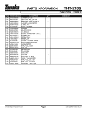
PARTS INFORMATION THT-210S CRANKCASE & FLYWHEEL • FIGURE 2 ITEM PART NUMBER DESCRIPTION 2-21 0720650090 CRANKCASE ASS'Y 2-22 09006500200 GASKET,CRANKCASE 2-23 99966122240 SEAL,OIL,#12227 2-24 99961600115 BEARING,BALL,6001 C3 2-25 33000200210 SHIM,12...99461050304 BOLT,HEX,5X30S 2-31 1552152380 ROTOR,MAGNETO 2-32 99201080011 WASHER,8 2-33 99210080012 WASHER,S,8 2-34 99101080011 NUT,8 2-35 10002100200 BOLT,STUD,6X22 www.tanakapowerequipment.com QTY COMMENTS 1 Includes bearings, seals and gasket 1 2 2 V Shims are as needed V V V 1 3 1 1 1 1 2 Page 2 custsvc@nikko-tanaka-usa...
PARTS INFORMATION THT-210S CRANKCASE & FLYWHEEL • FIGURE 2 ITEM PART NUMBER DESCRIPTION 2-21 0720650090 CRANKCASE ASS'Y 2-22 09006500200 GASKET,CRANKCASE 2-23 99966122240 SEAL,OIL,#12227 2-24 99961600115 BEARING,BALL,6001 C3 2-25 33000200210 SHIM,12...99461050304 BOLT,HEX,5X30S 2-31 1552152380 ROTOR,MAGNETO 2-32 99201080011 WASHER,8 2-33 99210080012 WASHER,S,8 2-34 99101080011 NUT,8 2-35 10002100200 BOLT,STUD,6X22 www.tanakapowerequipment.com QTY COMMENTS 1 Includes bearings, seals and gasket 1 2 2 V Shims are as needed V V V 1 3 1 1 1 1 2 Page 2 custsvc@nikko-tanaka-usa...
Parts List
Page 5
PARTS INFORMATION THT-210S FUEL SYSTEM • FIGURE 3 ITEM PART NUMBER DESCRIPTION 3-25 40306500200 GASKET,INTAKE 3-26 4040650090 SET,CARB INSULATOR 3-27 99464050254 BOLT,HEX HOLE,5X25WS 3-30 40206500200 GASKET,CARBURETOR 3-33 99967015000 O-RING,P15 3-35 4230650081 BODY,CLEANER 3-36 47006500200 COLLAR 3-37 5280650T20 LEVER,CHOKE 3-38 99204080030 WASHER,8 3-39 47601700200 BOARD,BLOW OVER CHECK 3-40 99210050012 WASHER,S,5 3-41 99011050602 SCREW,5X60 3-43 4460650021 FILTER,AIR 3-44...
PARTS INFORMATION THT-210S FUEL SYSTEM • FIGURE 3 ITEM PART NUMBER DESCRIPTION 3-25 40306500200 GASKET,INTAKE 3-26 4040650090 SET,CARB INSULATOR 3-27 99464050254 BOLT,HEX HOLE,5X25WS 3-30 40206500200 GASKET,CARBURETOR 3-33 99967015000 O-RING,P15 3-35 4230650081 BODY,CLEANER 3-36 47006500200 COLLAR 3-37 5280650T20 LEVER,CHOKE 3-38 99204080030 WASHER,8 3-39 47601700200 BOARD,BLOW OVER CHECK 3-40 99210050012 WASHER,S,5 3-41 99011050602 SCREW,5X60 3-43 4460650021 FILTER,AIR 3-44...
Parts List
Page 6
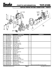
PARTS INFORMATION THT-210S MUFFLER, STARTER, FAN CASE & ENGINE COVER • FIGURE 4 ITEM PART NUMBER DESCRIPTION 4-3 7380650020 PROTECTOR,MUFFLER 4-4 73706500200 GASKET,MUFFLER 4-5 13306500200 SHIELD,HEAT 4-6 7040650091 MUFFLER SET 4-7 99201050011 WASHER,5 4-8 99051050503 BOLT,HEX,5X50 4-17 2030604A202 GROMMET 4-20 99463040184 BOLT,HEX,4x18PS 4-21 75106500200 GASKET,MUFFLER 4-22 7210650091 PIPE,TAIL SET 4-24 99434040081 SCREW,4X8/S 4-47 2770634F901 CLUTCH,ASSY 4-61 99072045164 SCREW,TAPPING,4.5X16 4-62 99425040128 BOLT,PS,4X12 4-67 1120651H80 CASE...
PARTS INFORMATION THT-210S MUFFLER, STARTER, FAN CASE & ENGINE COVER • FIGURE 4 ITEM PART NUMBER DESCRIPTION 4-3 7380650020 PROTECTOR,MUFFLER 4-4 73706500200 GASKET,MUFFLER 4-5 13306500200 SHIELD,HEAT 4-6 7040650091 MUFFLER SET 4-7 99201050011 WASHER,5 4-8 99051050503 BOLT,HEX,5X50 4-17 2030604A202 GROMMET 4-20 99463040184 BOLT,HEX,4x18PS 4-21 75106500200 GASKET,MUFFLER 4-22 7210650091 PIPE,TAIL SET 4-24 99434040081 SCREW,4X8/S 4-47 2770634F901 CLUTCH,ASSY 4-61 99072045164 SCREW,TAPPING,4.5X16 4-62 99425040128 BOLT,PS,4X12 4-67 1120651H80 CASE...
Parts List
Page 7
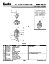
... THT-210S CARBURETOR • FIGURE 5 A small retainer (560-0217020), has been added to this model after serial # A099801 to prevent the barrel end of the throttle wire from coming detached from the carburetor. 0 ITEM PART NUMBER DESCRIPTION 5-0 4550651A90 CARBURETOR ASSY 5-1 54825140200 SCREW,THROTTLE 5-5 53925120200 SWIVEL 5-7 48925100200 RING,STOP 5-10 55025100200 O-RING 5-11 599200BW34 JET,MAIN,LONG,#34.5 5-13 ~ ~ ~ GASKET,PUMP 5-14 ~ ~ ~ DIAPHRAGM,PUMP 5-17 57825007200 SCREEN...
... THT-210S CARBURETOR • FIGURE 5 A small retainer (560-0217020), has been added to this model after serial # A099801 to prevent the barrel end of the throttle wire from coming detached from the carburetor. 0 ITEM PART NUMBER DESCRIPTION 5-0 4550651A90 CARBURETOR ASSY 5-1 54825140200 SCREW,THROTTLE 5-5 53925120200 SWIVEL 5-7 48925100200 RING,STOP 5-10 55025100200 O-RING 5-11 599200BW34 JET,MAIN,LONG,#34.5 5-13 ~ ~ ~ GASKET,PUMP 5-14 ~ ~ ~ DIAPHRAGM,PUMP 5-17 57825007200 SCREEN...

Parts List
Page 8
PARTS INFORMATION THT-210S FRONT HANDLE • FIGURE 6 ITEM PART NUMBER DESCRIPTION 6-1 2603329020 FRAME,HANDLE 6-2 2103324720 HANDLE,FRONT 6-3 27632710201 COLLAR,DAMPER B 6-4 26632750200 DAMPER,B 6-5 36832057200 WASHER,BRAKE SHAFT 6-6 99461050304 BOLT,HEX,5X30S 6-7 5053329020 CLIP 6-8 0403316080 SUPPORT,HANDLE 6-9 99051050403 BOLT,HEX,5X40 6-10 99210050062 WASHER,S,5 6-11 99201050061 WASHER,5 www.tanakapowerequipment.com QTY 1 1 4 4 4 4 1 1 2 2 2 Page 7 COMMENTS custsvc@nikko-tanaka-usa.com
PARTS INFORMATION THT-210S FRONT HANDLE • FIGURE 6 ITEM PART NUMBER DESCRIPTION 6-1 2603329020 FRAME,HANDLE 6-2 2103324720 HANDLE,FRONT 6-3 27632710201 COLLAR,DAMPER B 6-4 26632750200 DAMPER,B 6-5 36832057200 WASHER,BRAKE SHAFT 6-6 99461050304 BOLT,HEX,5X30S 6-7 5053329020 CLIP 6-8 0403316080 SUPPORT,HANDLE 6-9 99051050403 BOLT,HEX,5X40 6-10 99210050062 WASHER,S,5 6-11 99201050061 WASHER,5 www.tanakapowerequipment.com QTY 1 1 4 4 4 4 1 1 2 2 2 Page 7 COMMENTS custsvc@nikko-tanaka-usa.com

Parts List
Page 9
PARTS INFORMATION THT-210S REAR HANDLE • FIGURE 7 ITEM PART NUMBER DESCRIPTION 7-1 0513329020 HANDLE,B 7-2 0503329020 HANDLE,A 7-3 2303329020 LEVER,THROTTLE 7-4 2313329020 LEVER,SAFETY 7-5 23233160200 SPRING,THROTTLE LEVER 7-6 1703329080 BUTTON,STOP 7-7 2333329020 LEVER,LOCK 7-8 2453329020 SPRING 7-9 99201040011 WASHER,4 7-10 99341040101 SCREW,TAPPING,4X10 7-11 99072045164 SCREW,TAPPING,4.5X16 7-12 8853329080 WIRE,THROTTLE 7-13 2581165020 BUTTON,STOP 7-14 99011030101 SCREW.3x10 7-15 1640701501 TUBE,PROTECTION 150 7-16 92533160200 DECAL,STOP BUTTON www....
PARTS INFORMATION THT-210S REAR HANDLE • FIGURE 7 ITEM PART NUMBER DESCRIPTION 7-1 0513329020 HANDLE,B 7-2 0503329020 HANDLE,A 7-3 2303329020 LEVER,THROTTLE 7-4 2313329020 LEVER,SAFETY 7-5 23233160200 SPRING,THROTTLE LEVER 7-6 1703329080 BUTTON,STOP 7-7 2333329020 LEVER,LOCK 7-8 2453329020 SPRING 7-9 99201040011 WASHER,4 7-10 99341040101 SCREW,TAPPING,4X10 7-11 99072045164 SCREW,TAPPING,4.5X16 7-12 8853329080 WIRE,THROTTLE 7-13 2581165020 BUTTON,STOP 7-14 99011030101 SCREW.3x10 7-15 1640701501 TUBE,PROTECTION 150 7-16 92533160200 DECAL,STOP BUTTON www....
Parts List
Page 10
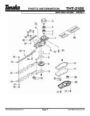
PARTS INFORMATION THT-210S GEAR CASE & BLADES • FIGURE 8 www.tanakapowerequipment.com Page 9 custsvc@nikko-tanaka-usa.com
PARTS INFORMATION THT-210S GEAR CASE & BLADES • FIGURE 8 www.tanakapowerequipment.com Page 9 custsvc@nikko-tanaka-usa.com


