
Parts List
Page 1
Illustrated Parts Manual Model Number: TPH-200/210 HEDGETRIMMER ATTACHMENT P/N 31778 Rev 000 Date 1-14-08 Nikko Tanaka Engineering U.S.A.,Ltd.• 1028 4th Street SW, Bldg B • Auburn, WA 98001 • Phone: (253) 333-1200 • Fax: (253) 333-1212 www.tanakapowerequipment.com custsvc@nikko-tanaka-usa.com
Illustrated Parts Manual Model Number: TPH-200/210 HEDGETRIMMER ATTACHMENT P/N 31778 Rev 000 Date 1-14-08 Nikko Tanaka Engineering U.S.A.,Ltd.• 1028 4th Street SW, Bldg B • Auburn, WA 98001 • Phone: (253) 333-1200 • Fax: (253) 333-1212 www.tanakapowerequipment.com custsvc@nikko-tanaka-usa.com
Parts List
Page 2
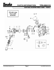
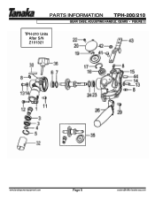
PARTS INFORMATION TPH-200/210 GEAR CASE, ADJUSTING HANDLE, GEARS • FIGURE 1 TPH-200 Units Prior to S/N W040350 www.tanakapowerequipment.com Page 1 custsvc@nikko-tanaka-usa.com
PARTS INFORMATION TPH-200/210 GEAR CASE, ADJUSTING HANDLE, GEARS • FIGURE 1 TPH-200 Units Prior to S/N W040350 www.tanakapowerequipment.com Page 1 custsvc@nikko-tanaka-usa.com
Parts List
Page 3
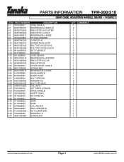
PARTS INFORMATION TPH-200/210 GEAR CASE, ADJUSTING HANDLE, GEARS • FIGURE 1 ITEM PART NUMBER DESCRIPTION 1-1 3003228520 GEAR,CASE,A 1-2 99961690100 BEARING,BALL,#6901 1-3 99961690101 BEARING,BALL,#6901ZZ 1-4 99352012002 RING,STOP,S12,OUTER 1-5 99351024002 RING,STOP,C-24,IN 1-6 99961608002 BEARING,BALL,#608Z 1-7 99351022002 RING,STOP,C22,IN 1-8 30032250801 FITTING,GREASE 1-9 99967041000 O-RING,P-41 1-10 99413060101 SCREW,PLUS,6x10P 1-11 99051050103 BOLT,HEX.HOLE,5X10 1-12...
PARTS INFORMATION TPH-200/210 GEAR CASE, ADJUSTING HANDLE, GEARS • FIGURE 1 ITEM PART NUMBER DESCRIPTION 1-1 3003228520 GEAR,CASE,A 1-2 99961690100 BEARING,BALL,#6901 1-3 99961690101 BEARING,BALL,#6901ZZ 1-4 99352012002 RING,STOP,S12,OUTER 1-5 99351024002 RING,STOP,C-24,IN 1-6 99961608002 BEARING,BALL,#608Z 1-7 99351022002 RING,STOP,C22,IN 1-8 30032250801 FITTING,GREASE 1-9 99967041000 O-RING,P-41 1-10 99413060101 SCREW,PLUS,6x10P 1-11 99051050103 BOLT,HEX.HOLE,5X10 1-12...
Parts List
Page 4
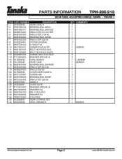
Units from S/N W040351 to Z101320 www.tanakapowerequipment.com Page 3 custsvc@nikko-tanaka-usa.com PARTS INFORMATION TPH-200/210 GEAR CASE, ADJUSTING HANDLE, GEARS • FIGURE 2 TPH-200 -
Units from S/N W040351 to Z101320 www.tanakapowerequipment.com Page 3 custsvc@nikko-tanaka-usa.com PARTS INFORMATION TPH-200/210 GEAR CASE, ADJUSTING HANDLE, GEARS • FIGURE 2 TPH-200 -
Parts List
Page 5
... KNOB,HANDLE 2-26 0333228081 GUIDE,SLIDE 2-27 1963228520 BOLT,SPECIAL 2-28 99210060062 WASHER,S,6 2-29 99053060153 BOLT,HEX,6X15 2-32 34833130200 COLLAR,B 2-35 3023228200 SET,GEAR & PINION 2-36 5123229820 KNOB,HANDLE 2-37 3053228222 SHAFT,GEAR 2-38 3813228920 NUT,SPECIAL 2-40 0713228221 SHIM 2-40 0713228222 SHIM 2-40 0713228223 SHIM 2-41 0963228920 COLLAR,26.8 2-44 0863228620 SEAL,GREASE,B 2-45 12132530200 NUT,CLAMP,BAR 2-46 7603228220 WASHER,1.6 2-47 99431060081 SCREW...
... KNOB,HANDLE 2-26 0333228081 GUIDE,SLIDE 2-27 1963228520 BOLT,SPECIAL 2-28 99210060062 WASHER,S,6 2-29 99053060153 BOLT,HEX,6X15 2-32 34833130200 COLLAR,B 2-35 3023228200 SET,GEAR & PINION 2-36 5123229820 KNOB,HANDLE 2-37 3053228222 SHAFT,GEAR 2-38 3813228920 NUT,SPECIAL 2-40 0713228221 SHIM 2-40 0713228222 SHIM 2-40 0713228223 SHIM 2-41 0963228920 COLLAR,26.8 2-44 0863228620 SEAL,GREASE,B 2-45 12132530200 NUT,CLAMP,BAR 2-46 7603228220 WASHER,1.6 2-47 99431060081 SCREW...
Parts List
Page 6
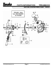
PARTS INFORMATION TPH-200/210 GEAR CASE, ADJUSTING HANDLE, GEARS • FIGURE 3 TPH-210 Units After S/N Z101321 www.tanakapowerequipment.com Page 5 custsvc@nikko-tanaka-usa.com
PARTS INFORMATION TPH-200/210 GEAR CASE, ADJUSTING HANDLE, GEARS • FIGURE 3 TPH-210 Units After S/N Z101321 www.tanakapowerequipment.com Page 5 custsvc@nikko-tanaka-usa.com
Parts List
Page 7
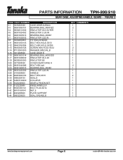
PARTS INFORMATION TPH-200/210 GEAR CASE, ADJUSTING HANDLE, GEARS • FIGURE 3 ITEM PART NUMBER DESCRIPTION 3-1 3003223020 CASE,GEAR,A,26mm 3-3 99961690101 BEARING,BALL,#6901ZZ 3-4 99352012002 RING,STOP,S12,OUTER 3-5 99351024002 RING,STOP,C-24,IN 3-6 99961608013 BEARING,BALL,#608Z 3-7 99351022002 RING,STOP,C22,IN 3-8 30032250801 FITTING,GREASE 3-11 99051050103 BOLT,HEX.HOLE,5X10 3-12 99461050254 BOLT,HEX HOLE,5X25S 3-13 99053060125 SCREW,HEX HOLE 6X12 3-14...
PARTS INFORMATION TPH-200/210 GEAR CASE, ADJUSTING HANDLE, GEARS • FIGURE 3 ITEM PART NUMBER DESCRIPTION 3-1 3003223020 CASE,GEAR,A,26mm 3-3 99961690101 BEARING,BALL,#6901ZZ 3-4 99352012002 RING,STOP,S12,OUTER 3-5 99351024002 RING,STOP,C-24,IN 3-6 99961608013 BEARING,BALL,#608Z 3-7 99351022002 RING,STOP,C22,IN 3-8 30032250801 FITTING,GREASE 3-11 99051050103 BOLT,HEX.HOLE,5X10 3-12 99461050254 BOLT,HEX HOLE,5X25S 3-13 99053060125 SCREW,HEX HOLE 6X12 3-14...
Parts List
Page 9
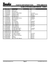
PARTS INFORMATION TPH-200/210 BLADES, CUTTER GUIDE, BLADE HARDWARE • FIGURE 4 ITEM PART NUMBER DESCRIPTION 4-1 1003228280 SHAFT,CAM 4-2 1013316022 ROD,CAM 4-3 0753228020 PLATE,GUIDE 4-4 1223316021 GUIDE,CUTTER 625MM 4-4 1223228721 GUIDE,CUTTER 4-4 1223228621 GUIDE,CUTTER 4-5 CB-21A BLADE,A,DS,22" 4-5 1203228721 BLADE,A,DS,22" 4-6 1243320221 BOLT,CUTTER FIXING,A 4-6 1243228720 BOLT,FIXING,A 4-7 12933202201 WASHER,7 4-8 1233317A20 NUT,SPECIAL 4-8 99182060001 NUT,FLANGE,6 4-9 99052060165 BOLT,HEX,6X16 4-9 99052060165 BOLT,HEX,6X16 4-10 08533160200 SEAL,GREASE A ...
PARTS INFORMATION TPH-200/210 BLADES, CUTTER GUIDE, BLADE HARDWARE • FIGURE 4 ITEM PART NUMBER DESCRIPTION 4-1 1003228280 SHAFT,CAM 4-2 1013316022 ROD,CAM 4-3 0753228020 PLATE,GUIDE 4-4 1223316021 GUIDE,CUTTER 625MM 4-4 1223228721 GUIDE,CUTTER 4-4 1223228621 GUIDE,CUTTER 4-5 CB-21A BLADE,A,DS,22" 4-5 1203228721 BLADE,A,DS,22" 4-6 1243320221 BOLT,CUTTER FIXING,A 4-6 1243228720 BOLT,FIXING,A 4-7 12933202201 WASHER,7 4-8 1233317A20 NUT,SPECIAL 4-8 99182060001 NUT,FLANGE,6 4-9 99052060165 BOLT,HEX,6X16 4-9 99052060165 BOLT,HEX,6X16 4-10 08533160200 SEAL,GREASE A ...
Owner's Manual
Page 2
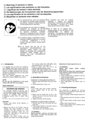
... and that could contribute to unsafe conditions. Assembly procedures Installation of support handle (1) (Fig.2-2) 1. Install support handle (1) onto gear case by holding the support handle (3). 4. Then tighten hex. hole screws securely. 71\ WARNING! During operation, hold the unit firmly with over 26 ml (cc) engines. Always stop engine before making adjustments. Trimming techniques This attachment is designed for certain TANAKA brush cutters. Check direction branch will not come off...
... and that could contribute to unsafe conditions. Assembly procedures Installation of support handle (1) (Fig.2-2) 1. Install support handle (1) onto gear case by holding the support handle (3). 4. Then tighten hex. hole screws securely. 71\ WARNING! During operation, hold the unit firmly with over 26 ml (cc) engines. Always stop engine before making adjustments. Trimming techniques This attachment is designed for certain TANAKA brush cutters. Check direction branch will not come off...


