Instruction Manual
Page 1
.... Model. Cautions 3 3. Components 3 4. Part Names & Functions 4 5. Line Lock Phase 12 8. as found on the label on use , and keep it handy for future reference. IK-VR01A Serial No. Connections and Operations 5 6. No. Specifications 14 11. CCD COLOR CAMERA IK-VR01A INSTRUCTION MANUAL Please read this manual thoroughly before use and Installation 12 9.
.... Model. Cautions 3 3. Components 3 4. Part Names & Functions 4 5. Line Lock Phase 12 8. as found on the label on use , and keep it handy for future reference. IK-VR01A Serial No. Connections and Operations 5 6. No. Specifications 14 11. CCD COLOR CAMERA IK-VR01A INSTRUCTION MANUAL Please read this manual thoroughly before use and Installation 12 9.
Instruction Manual
Page 2
... Warnings the video product due to the product. label. Cleaning Do not overload power supply and extension cords Disconnect this a soft and weak place, the camera unit may result proper ventilation is in fire, electric shock or 12.Installation other hazards. 8. The video Disconnect this video product on the product and...
... Warnings the video product due to the product. label. Cleaning Do not overload power supply and extension cords Disconnect this a soft and weak place, the camera unit may result proper ventilation is in fire, electric shock or 12.Installation other hazards. 8. The video Disconnect this video product on the product and...
Instruction Manual
Page 3
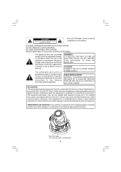
... serial No. NO USER SERVICEABLE PARTS INSIDE. DO NOT REMOVE COVER (OR BACK). Operation of the FCC Rules. • The CAUTION label, shown on the camera.
... serial No. NO USER SERVICEABLE PARTS INSIDE. DO NOT REMOVE COVER (OR BACK). Operation of the FCC Rules. • The CAUTION label, shown on the camera.
Instruction Manual
Page 4
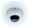
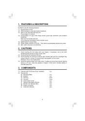
... 50dB Signal-To Noise Ratio (6) Power supply- FEATURES & DESCRIPTION IK-VR01A has the following features: (1) Flush/Surface mount. (2) IP66 Standard for dust and water resistance. (3) Built in images. This camera automatically detects the power. (7) BLC, AGC, and Line-Lock (AC24V...) 2. However, this event, relocate cables or reinstall equipment. 3. In this is not a malfunction. (4) Install the camera away from video noise. If necessary, use a soft cloth moistened with Tint Dome Cover installed) (2) Accessories (a) Mounting Base (b) Bracket (c) Screw A ...
... 50dB Signal-To Noise Ratio (6) Power supply- FEATURES & DESCRIPTION IK-VR01A has the following features: (1) Flush/Surface mount. (2) IP66 Standard for dust and water resistance. (3) Built in images. This camera automatically detects the power. (7) BLC, AGC, and Line-Lock (AC24V...) 2. However, this event, relocate cables or reinstall equipment. 3. In this is not a malfunction. (4) Install the camera away from video noise. If necessary, use a soft cloth moistened with Tint Dome Cover installed) (2) Accessories (a) Mounting Base (b) Bracket (c) Screw A ...
Instruction Manual
Page 5
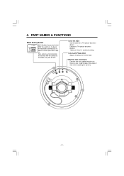
... to adjust the angle of the line lock. Clockwise: The picture becomes brighter. Line Lock Phase ADJ Adjusts the phase of view when installing the camera. - 4 - Used to line lock with the switch on , it adjusts the backlight automatically to obtain the best possible image. Available only with the supplied monitor...
... to adjust the angle of the line lock. Clockwise: The picture becomes brighter. Line Lock Phase ADJ Adjusts the phase of view when installing the camera. - 4 - Used to line lock with the switch on , it adjusts the backlight automatically to obtain the best possible image. Available only with the supplied monitor...
Instruction Manual
Page 6
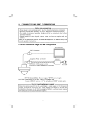
... / 12V DC power supply CAUTION : Never input 24V AC and 12V DC at least 5w consumption. Do not overload power supply Since this camera uses 24V AC UL Listed Class 2 power supply or 12V DC power supply, it should be connected, refer to the operations manuals of equipment... to be connected to black cable. Because the IK-VR01A uses a mechanism, a sufficient power supply with the camera. Refer to their operation manuals. • Coaxial cables for video signals and the power cord are not supplied with adequate...
... / 12V DC power supply CAUTION : Never input 24V AC and 12V DC at least 5w consumption. Do not overload power supply Since this camera uses 24V AC UL Listed Class 2 power supply or 12V DC power supply, it should be connected, refer to the operations manuals of equipment... to be connected to black cable. Because the IK-VR01A uses a mechanism, a sufficient power supply with the camera. Refer to their operation manuals. • Coaxial cables for video signals and the power cord are not supplied with adequate...
Instruction Manual
Page 7
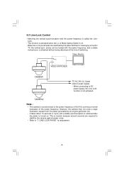
... a large fluctuation caused from the power generated by an engine generator, etc. • It takes about 10 seconds or more cameras are required to stabilize the camera against power noise. • Refer to the power frequency of 60±1Hz covering a normal fluctuation of the power frequency. CAMERA2... Note : • The camera is synchronized to "7. LINE-LOCK PHASE" for viewing by the video switcher for adjustment. - 6 - phase can be locked with the power ...
... a large fluctuation caused from the power generated by an engine generator, etc. • It takes about 10 seconds or more cameras are required to stabilize the camera against power noise. • Refer to the power frequency of 60±1Hz covering a normal fluctuation of the power frequency. CAMERA2... Note : • The camera is synchronized to "7. LINE-LOCK PHASE" for viewing by the video switcher for adjustment. - 6 - phase can be locked with the power ...
Instruction Manual
Page 8
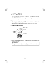
... bracket weighs 2.1kg. • When installing to surfaces of other materials, use the screws to fix it firmly. 6-1 Adjust the Angle of the camera and the cable from the designated power supply with respective connectors. • Screws for transportation. - 7 - The screws are not supplied with the ...unit. Note : • The weight (camera body only) is about 1.3kg. Use appropriate screws. Important Notice : Be sure to temporarily fix the top cover for fixing the camera and mounting base to the ceiling or wall are used to remove three silver ...
... bracket weighs 2.1kg. • When installing to surfaces of other materials, use the screws to fix it firmly. 6-1 Adjust the Angle of the camera and the cable from the designated power supply with respective connectors. • Screws for transportation. - 7 - The screws are not supplied with the ...unit. Note : • The weight (camera body only) is about 1.3kg. Use appropriate screws. Important Notice : Be sure to temporarily fix the top cover for fixing the camera and mounting base to the ceiling or wall are used to remove three silver ...
Instruction Manual
Page 10
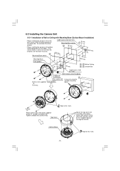
...55 mm 85 mm A , C Wall or Ceiling B , D Junction Box Cable access hole ø27 mm With female screw for the cables. Camera Base Align to this mark. - 9 - The camera body is water-resistant but the brackets are not water-resistant. Top Cover Align to this mark. Do not block the drain... groove. • When installing the camera unit outdoor, make waterproof for piping Cable exit (sideway) D Rear cable hole In case of the dome cover) and secure it with three supplied...
...55 mm 85 mm A , C Wall or Ceiling B , D Junction Box Cable access hole ø27 mm With female screw for the cables. Camera Base Align to this mark. - 9 - The camera body is water-resistant but the brackets are not water-resistant. Top Cover Align to this mark. Do not block the drain... groove. • When installing the camera unit outdoor, make waterproof for piping Cable exit (sideway) D Rear cable hole In case of the dome cover) and secure it with three supplied...
Instruction Manual
Page 11
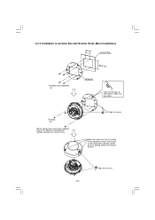
Mount the top cover (the assembly of the bracket, which has two sides. Screws x3 Mount camera base with three security screws by the supplied special hexangular wrench. - 10 - Align to Junction Box with Bracket (Flush Mount Installation) 46 mm Junction Box 83.5 mm Screws (not supplied) x4 Bracket Note the direction of the top dome cover) and secure it firmly with three supplied screws B. (Shorter screw(M4x10)) Tighten and lock the screws firmly. 6-2-2 Installation to this mark. Align the marks.
Mount the top cover (the assembly of the bracket, which has two sides. Screws x3 Mount camera base with three security screws by the supplied special hexangular wrench. - 10 - Align to Junction Box with Bracket (Flush Mount Installation) 46 mm Junction Box 83.5 mm Screws (not supplied) x4 Bracket Note the direction of the top dome cover) and secure it firmly with three supplied screws B. (Shorter screw(M4x10)) Tighten and lock the screws firmly. 6-2-2 Installation to this mark. Align the marks.
Instruction Manual
Page 13
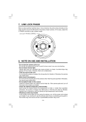
... quality of images may deteriorate or internal parts may malfunction. • Never touch internal parts Do not touch the internal parts of each camera. Line Lock V PHASE CONTROL 8. If the camera gets wet, turn off the power and contact your dealer. • Check the ambient temperature and humidity Avoid using the... appear on the video monitor due to strong shock of vibration. NOTE ON USE AND INSTALLATION • Do not aim the camera at the sun Do not aim the camera at the sun or point it , the trouble may much worse and an unpredictable accident may malfunction. • Do not ...
... quality of images may deteriorate or internal parts may malfunction. • Never touch internal parts Do not touch the internal parts of each camera. Line Lock V PHASE CONTROL 8. If the camera gets wet, turn off the power and contact your dealer. • Check the ambient temperature and humidity Avoid using the... appear on the video monitor due to strong shock of vibration. NOTE ON USE AND INSTALLATION • Do not aim the camera at the sun Do not aim the camera at the sun or point it , the trouble may much worse and an unpredictable accident may malfunction. • Do not ...
Instruction Manual
Page 14
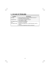
Check Points • Are the camera and connected equipment turned on? • Are cables connected correctly? • Is the monitor TV adjusted correctly? • Is the lighting too weak? • Is the lens focus adjusted? • Is the lens or cover dirty? • Are there any large barrier or bright illumination near the camera? • Is the lens iris adjustment volume correctly set? - 13 - The image is out of focus. IN CASE OF PROBLEMS Condition No image Unnatural color The image is dark. 9.
Check Points • Are the camera and connected equipment turned on? • Are cables connected correctly? • Is the monitor TV adjusted correctly? • Is the lighting too weak? • Is the lens focus adjusted? • Is the lens or cover dirty? • Are there any large barrier or bright illumination near the camera? • Is the lens iris adjustment volume correctly set? - 13 - The image is out of focus. IN CASE OF PROBLEMS Condition No image Unnatural color The image is dark. 9.
Instruction Manual
Page 15
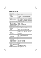
... Temperature -10°C~50°C 90%RH max Storage Temperature -20°C~60°C 70%RH max Water proof:IP66 7. Mechanical Weight Camera : 1.3kg, Mounting Base : 0.6kg, Bracket : 0.2kg Dimension Camera : 170mm (D) x 150mm (H) with Mounting Base : 175mm (D) x 155mm (H) 4. Regulation Safety UL2044 Dust and Water Resistance IP66 Emission FCC Class A / DOC ClassA Design...
... Temperature -10°C~50°C 90%RH max Storage Temperature -20°C~60°C 70%RH max Water proof:IP66 7. Mechanical Weight Camera : 1.3kg, Mounting Base : 0.6kg, Bracket : 0.2kg Dimension Camera : 170mm (D) x 150mm (H) with Mounting Base : 175mm (D) x 155mm (H) 4. Regulation Safety UL2044 Dust and Water Resistance IP66 Emission FCC Class A / DOC ClassA Design...
