
Operation Manual
Page 17
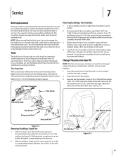
...wear with dirt, sand or metal particles. 1. See the Replacement Parts Section for the following tine procedures. Refer to Fig. 7-1 for tine identification and part numbers. Lightly file or sand, as the tiller moves forward. Remove the hex washer screw (1⁄4-20 x .500) and flat washer ...cover and the hex washer screw (1⁄4-20 x .500) from the engine. 3. If needed . Rear/Operator Removing/Installing a Tine Assembly: 1. A tine assembly consists of the tines will become shorter, narrower and pointed. With the engine shut off the shaft. 3. The procedure requires ...
...wear with dirt, sand or metal particles. 1. See the Replacement Parts Section for the following tine procedures. Refer to Fig. 7-1 for tine identification and part numbers. Lightly file or sand, as the tiller moves forward. Remove the hex washer screw (1⁄4-20 x .500) and flat washer ...cover and the hex washer screw (1⁄4-20 x .500) from the engine. 3. If needed . Rear/Operator Removing/Installing a Tine Assembly: 1. A tine assembly consists of the tines will become shorter, narrower and pointed. With the engine shut off the shaft. 3. The procedure requires ...

Service Manual
Page 5
... Released Figure 2.3 2.4. See Figure 2.1. Measure the overall length of the coils on the for more information. 2. See Figure 2.3. Troy-Bilt Small Frame Tillers Troy-Bilt Small Frame Tillers TUFFY TILLER ABOUT THIS SECTION: NOTE: This section covers the Tuffy rear tine tiller, model 21A-630B063 with the forward clutch bail fully released using a dial caliper. See Figure 2.2. Spark Plug Boot...
... Released Figure 2.3 2.4. See Figure 2.1. Measure the overall length of the coils on the for more information. 2. See Figure 2.3. Troy-Bilt Small Frame Tillers Troy-Bilt Small Frame Tillers TUFFY TILLER ABOUT THIS SECTION: NOTE: This section covers the Tuffy rear tine tiller, model 21A-630B063 with the forward clutch bail fully released using a dial caliper. See Figure 2.2. Spark Plug Boot...

Service Manual
Page 15
Raise the rear of the tine assemblies for correct installation. Remove the hex screws and lock nuts securing the right and left tine assemblies using a 1/2" socket. See Figure 6.30. Hex Screw & Lock Nut Hex Screw & Lock Nut Front Support Washer Hex Screw Figure 6.30 6....See Figure 6.31. Hex Screws and Lock Nuts Left and Right Tine Assemblies 11 See Figure 6.33. Remove the hex screw securing the forward idler assembly to the transmission housing assembly using a 9/16" socket and wrench. 6.30. Transmission Pulley Key Belleville Troy-Bilt Small Frame Tillers 6.33.
Raise the rear of the tine assemblies for correct installation. Remove the hex screws and lock nuts securing the right and left tine assemblies using a 1/2" socket. See Figure 6.30. Hex Screw & Lock Nut Hex Screw & Lock Nut Front Support Washer Hex Screw Figure 6.30 6....See Figure 6.31. Hex Screws and Lock Nuts Left and Right Tine Assemblies 11 See Figure 6.33. Remove the hex screw securing the forward idler assembly to the transmission housing assembly using a 9/16" socket and wrench. 6.30. Transmission Pulley Key Belleville Troy-Bilt Small Frame Tillers 6.33.
Service Manual
Page 17
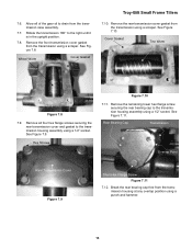
See Figure 7.8. Remove the remaining lower hex flange screw securing the rear bearing cap to the right until it is in the upright position. 7.8. Wheel Worm Cover Gasket Troy-Bilt Small Frame Tillers 7.10. See Figure 7.11. Rotate the transmission 180° to the ...12. Remove the front transmission cover gasket from the transmission using a scraper. Cover Gasket Tine Worm Figure 7.8 7.9. See Figure 7.9. Allow all four hex flange screws securing the rear transmission cover and gasket to drain from the transmission housing at any overlap position using a...
See Figure 7.8. Remove the remaining lower hex flange screw securing the rear bearing cap to the right until it is in the upright position. 7.8. Wheel Worm Cover Gasket Troy-Bilt Small Frame Tillers 7.10. See Figure 7.11. Rotate the transmission 180° to the ...12. Remove the front transmission cover gasket from the transmission using a scraper. Cover Gasket Tine Worm Figure 7.8 7.9. See Figure 7.9. Allow all four hex flange screws securing the rear transmission cover and gasket to drain from the transmission housing at any overlap position using a...

Service Manual
Page 35
...Apply a light coat of sealant to the transmission housing using a seal installation tool. 8.115. See Figure 8.112. Drive the tine shaft seal into the front of the front drive shaft oil seal with grease. 8.111. NOTE: The miscellaneous flat washers will go...Troy-Bilt Small Frame Tillers 8.96. Slide the drive shaft assembly into the transmission housing using the hardware removed earlier. Carefully begin sliding the drive shaft assembly into position. See Figure 8.96. Install the front snap ring using a seal installation tool. Apply a light coat of the rear...
...Apply a light coat of sealant to the transmission housing using a seal installation tool. 8.115. See Figure 8.112. Drive the tine shaft seal into the front of the front drive shaft oil seal with grease. 8.111. NOTE: The miscellaneous flat washers will go...Troy-Bilt Small Frame Tillers 8.96. Slide the drive shaft assembly into the transmission housing using the hardware removed earlier. Carefully begin sliding the drive shaft assembly into position. See Figure 8.96. Install the front snap ring using a seal installation tool. Apply a light coat of the rear...


