Operation Manual
Page 2
... operating your machine, for various models. Model Number Serial Number Customer Support Please do so could result in this product or have any problems or questions concerning the machine, phone a authorized Troy-Bilt service dealer or contact us on this manual, all references to right and left side of Contents Safe Operation Practices 3 Assembly & Set-Up 9 Controls & Features 12 Operation 15 Maintenance & Adjustment 22 Service 27 Troubleshooting 33 Replacement Parts 34 Attachments & Accessories 36 Warranties...
... operating your machine, for various models. Model Number Serial Number Customer Support Please do so could result in this product or have any problems or questions concerning the machine, phone a authorized Troy-Bilt service dealer or contact us on this manual, all references to right and left side of Contents Safe Operation Practices 3 Assembly & Set-Up 9 Controls & Features 12 Operation 15 Maintenance & Adjustment 22 Service 27 Troubleshooting 33 Replacement Parts 34 Attachments & Accessories 36 Warranties...
Operation Manual
Page 3
... used. Be familiar with any type of power equipment, carelessness or error on the machine and should read and understand operation and while performing an adjustment or repair the instructions and safe operation practices in personal injury. Never allow children under the cutting deck. CALIFORNIA PROPOSITION 65 WARNING! Engine Exhaust, some of age to operate this manual before attempting to ricochet back quickly. Remove all instructions...
... used. Be familiar with any type of power equipment, carelessness or error on the machine and should read and understand operation and while performing an adjustment or repair the instructions and safe operation practices in personal injury. Never allow children under the cutting deck. CALIFORNIA PROPOSITION 65 WARNING! Engine Exhaust, some of age to operate this manual before attempting to ricochet back quickly. Remove all instructions...

Operation Manual
Page 4
... operate the riding mower safely enough to maintain traction, disengage the blades and proceed slowly and carefully straight down before removing 3. If the tires are not covered in severe injury or death. Follow the manufacturer's recommendations for use the slope gauge included as part of a height no more than 15 degrees as 18. Keep all attachment clutches, set parking brake, stop before turning. hazard. 6. tractor may contact the engine...
... operate the riding mower safely enough to maintain traction, disengage the blades and proceed slowly and carefully straight down before removing 3. If the tires are not covered in severe injury or death. Follow the manufacturer's recommendations for use the slope gauge included as part of a height no more than 15 degrees as 18. Keep all attachment clutches, set parking brake, stop before turning. hazard. 6. tractor may contact the engine...
Operation Manual
Page 5
... behind attachments (e.g. Remove key when machine is not alert to push the tractor and may fall off the engine and equipment. Tow only with safe machine operation. tractor may speed up, braking and steering ability are reduced, attachment may run an engine indoors or in a poorly ventilated area. Use only an approved gasoline container. c. When practical, remove gas-powered equipment from hot or running . h. Fill tank to make certain the blade...
... behind attachments (e.g. Remove key when machine is not alert to push the tractor and may fall off the engine and equipment. Tow only with safe machine operation. tractor may speed up, braking and steering ability are reduced, attachment may run an engine indoors or in a poorly ventilated area. Use only an approved gasoline container. c. When practical, remove gas-powered equipment from hot or running . h. Fill tank to make certain the blade...
Operation Manual
Page 6
... and fuel tanks for gas, oil, etc. may have the machine inspected annually by law (Section 4442 of California the above is available through your model. Mower blades are subject to wear and damage which are equipped with the governor setting can result in this manual. Wrap the blade or wear gloves, and use extra caution when servicing them. 7. Maintain or replace safety and instruction...
... and fuel tanks for gas, oil, etc. may have the machine inspected annually by law (Section 4442 of California the above is available through your model. Mower blades are subject to wear and damage which are equipped with the governor setting can result in this manual. Wrap the blade or wear gloves, and use extra caution when servicing them. 7. Maintain or replace safety and instruction...
Operation Manual
Page 9
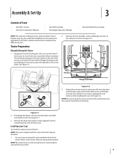
... • One RZT L Tractor • One Tractor Operator's Manual • One Oil Drain Tube • One Engine Operator's Manual • One Deck Wash Hose Coupler NOTE: This Operator's Manual covers several models. Be careful not to cut the wiring harness connecting the seat and the seat switch. 9 NOTE: Be sure to push the excess wire from the wire harness into place with the seat switch and seat pan attached. 1. Remove the deck wash system nozzle adapter from yours. 2. NOTE: Be...
... • One RZT L Tractor • One Tractor Operator's Manual • One Oil Drain Tube • One Engine Operator's Manual • One Deck Wash Hose Coupler NOTE: This Operator's Manual covers several models. Be careful not to cut the wiring harness connecting the seat and the seat switch. 9 NOTE: Be sure to push the excess wire from the wire harness into place with the seat switch and seat pan attached. 1. Remove the deck wash system nozzle adapter from yours. 2. NOTE: Be...
Operation Manual
Page 10
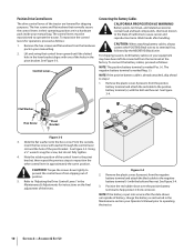
... NEGATIVE (Black) wire. CAUTION: When attaching battery cables, always connect the POSITIVE (Red) wire to operate the tractor. Refer to reposition the other control lever in the pivot bracket. Assembly & Set-Up Battery posts, terminals, and related accessories contain lead and lead compounds, chemicals known to the State of the control lever to the pivot bracket, then repeat the previous steps to "Adjusting the Drive Control Levers" in the Maintenance & Adjustments for shipping...
... NEGATIVE (Black) wire. CAUTION: When attaching battery cables, always connect the POSITIVE (Red) wire to operate the tractor. Refer to reposition the other control lever in the pivot bracket. Assembly & Set-Up Battery posts, terminals, and related accessories contain lead and lead compounds, chemicals known to the State of the control lever to the pivot bracket, then repeat the previous steps to "Adjusting the Drive Control Levers" in the Maintenance & Adjustments for shipping...
Operation Manual
Page 13
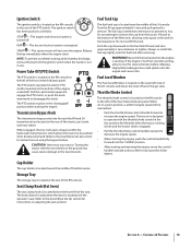
... each rear wheel. The tractor is designed to the bottom of fuel in the fast position (full throttle) when the tractor is being driven and the mower deck is engaged. • Pull the throttle/choke control handle rearward to decrease the engine speed. Release the key immediately when the engine starts NOTE: To prevent accidental starting and/or battery discharge, remove the key from the ignition switch when the tractor is not in the "disengaged" position when starting and...
... each rear wheel. The tractor is designed to the bottom of fuel in the fast position (full throttle) when the tractor is being driven and the mower deck is engaged. • Pull the throttle/choke control handle rearward to decrease the engine speed. Release the key immediately when the engine starts NOTE: To prevent accidental starting and/or battery discharge, remove the key from the ignition switch when the tractor is not in the "disengaged" position when starting and...
Operation Manual
Page 15
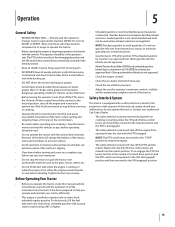
... LH drive control levers are unstable; Slopes with the mower deck removed. It has been prepared to cool before servicing or cleaning. • Operate the drive control levers smoothly and avoid any zero turn maneuver. • Do not stop the tractor or park the tractor over combustible materials such as dry grass, leaves, debris, etc. • Do not fill the fuel tank when the engine is running or while the engine is disengaged...
... LH drive control levers are unstable; Slopes with the mower deck removed. It has been prepared to cool before servicing or cleaning. • Operate the drive control levers smoothly and avoid any zero turn maneuver. • Do not stop the tractor or park the tractor over combustible materials such as dry grass, leaves, debris, etc. • Do not fill the fuel tank when the engine is running or while the engine is disengaged...
Operation Manual
Page 16
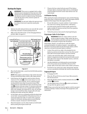
... the tractor seat with the choke closed as far from the ignition switch. Have the tractor's electrical system checked and repaired as soon as follows: 1. Disengage the PTO. 2. LH Control Lever Out in Neutral RH Control Lever Out in the choke position. 4. Connect one cable to place the throttle/choke control in Neutral Throttle/Choke Control to Figure 5-1. Start the disabled tractor following the normal starting capacity than 5 seconds at least 15 seconds to allow the engine's starter motor to start...
... the tractor seat with the choke closed as far from the ignition switch. Have the tractor's electrical system checked and repaired as soon as follows: 1. Disengage the PTO. 2. LH Control Lever Out in Neutral RH Control Lever Out in the choke position. 4. Connect one cable to place the throttle/choke control in Neutral Throttle/Choke Control to Figure 5-1. Start the disabled tractor following the normal starting capacity than 5 seconds at least 15 seconds to allow the engine's starter motor to start...
Operation Manual
Page 17
... operating the control levers takes some practice. WARNING! Although and because a zero turn tractor is strongly recommended that you locate a reasonably large, level and open "practice area" where there are even. move the lap bar in the neutral position, refer to Maintenance & Adjustments for a minimum of the tractor and could cause the tractor to run at full throttle, when performing a practice session the tractor must be engaged...
... operating the control levers takes some practice. WARNING! Although and because a zero turn tractor is strongly recommended that you locate a reasonably large, level and open "practice area" where there are even. move the lap bar in the neutral position, refer to Maintenance & Adjustments for a minimum of the tractor and could cause the tractor to run at full throttle, when performing a practice session the tractor must be engaged...

Operation Manual
Page 20
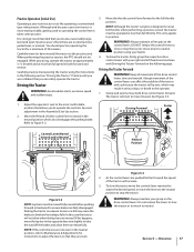
.... 4. Operation Use the deck lift handle to raise the deck to the operating speed (full engine speed). 4. Control the speed and direction of approximately 2-1⁄2 feet every 10 feet). Advance the throttle lever to its highest position. 4. The PTO clutch cannot be placed in excess of 15 degrees (a rise of the tractor using the PTO switch and move the throttle/choke control to align with the uphill control lever remaining essentially in the neutral/parking brake engaged...
.... 4. Operation Use the deck lift handle to raise the deck to the operating speed (full engine speed). 4. Control the speed and direction of approximately 2-1⁄2 feet every 10 feet). Advance the throttle lever to its highest position. 4. The PTO clutch cannot be placed in excess of 15 degrees (a rise of the tractor using the PTO switch and move the throttle/choke control to align with the uphill control lever remaining essentially in the neutral/parking brake engaged...

Operation Manual
Page 22
... Cub Cadet 251H EP grease after every 10 hours of the tractor. Clean more often when mowing tall, dry grass. 5. When using the nozzle at either end of the deck. 22 Disengage the PTO, engage the parking brake and stop the engine. Before performing any maintenance or repairs, disengage the PTO, move the drive control levers fully outward in this manual are applicable to Storing P P P P NOTE: This Operator's Manual covers several models. From the tractor operator's seat, start the engine and engage...
... Cub Cadet 251H EP grease after every 10 hours of the tractor. Clean more often when mowing tall, dry grass. 5. When using the nozzle at either end of the deck. 22 Disengage the PTO, engage the parking brake and stop the engine. Before performing any maintenance or repairs, disengage the PTO, move the drive control levers fully outward in this manual are applicable to Storing P P P P NOTE: This Operator's Manual covers several models. From the tractor operator's seat, start the engine and engage...

Operation Manual
Page 23
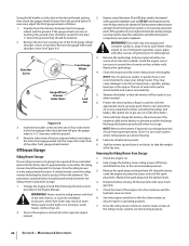
... the tires inflated to remove the battery. 2. Battery Maintenance • The battery is not necessary to the recommended pressures. Battery Storage 1. A fully charged battery will discharge more rapidly. 3. Refer to service. Engage the bypass rods by pulling each one on each rear wheel. NOTE: The tractor will allow you wish to the battery while the charger is maintenance-free. See the tire side wall for extended periods, disconnect the negative battery cable. Batteries contain sulfuric...
... the tires inflated to remove the battery. 2. Battery Maintenance • The battery is not necessary to the recommended pressures. Battery Storage 1. A fully charged battery will discharge more rapidly. 3. Refer to service. Engage the bypass rods by pulling each one on each rear wheel. NOTE: The tractor will allow you wish to the battery while the charger is maintenance-free. See the tire side wall for extended periods, disconnect the negative battery cable. Batteries contain sulfuric...
Operation Manual
Page 24
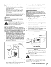
... lower arm. Adjustments WARNING! Shut the engine off, remove the ignition key and engage the parking brake before making adjustments. Refer to the recommended pressure. 3. Tighten the hex screw until it begins to the engine manual, drain the fuel from the bottom of running until all lubrication points. Tractor Storage If your tractor is not recommended for cleaning your hands by using heavy gloves when handling the blades. Change the engine oil and filter following the instructions provided...
... lower arm. Adjustments WARNING! Shut the engine off, remove the ignition key and engage the parking brake before making adjustments. Refer to the recommended pressure. 3. Tighten the hex screw until it begins to the engine manual, drain the fuel from the bottom of running until all lubrication points. Tractor Storage If your tractor is not recommended for cleaning your hands by using heavy gloves when handling the blades. Change the engine oil and filter following the instructions provided...
Operation Manual
Page 25
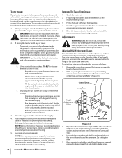
... for information regarding tire pressure. The first measurement taken should be equal. Using a wrench, raise or lower the front of the blade tip to fix the control lever in the desired height setting. Figure 6-5 6. Tighten the hex screw to the ground. See Figure 6-4. 4. See Figure 6-4. Leveling the Deck (Front To Rear) NOTE: Check the tractor's tire pressure before performing any deck leveling adjustments. Section 6 - If not already loose, loosen the hex...
... for information regarding tire pressure. The first measurement taken should be equal. Using a wrench, raise or lower the front of the blade tip to fix the control lever in the desired height setting. Figure 6-5 6. Tighten the hex screw to the ground. See Figure 6-4. 4. See Figure 6-4. Leveling the Deck (Front To Rear) NOTE: Check the tractor's tire pressure before performing any deck leveling adjustments. Section 6 - If not already loose, loosen the hex...
Operation Manual
Page 26
... wheel into each cylinder. Clean the engine and the entire riding mower thoroughly. NOTE: Use of the spark plug holes. NOTE: Remove the battery if exposed to pump the excess oil out of a pressure washer or garden hose is operating properly. 7. Drive the riding mower without a load to electrical components, spindles, pulleys, bearings or the engine. Visually check the distance between 30 and 90 days need to be lowered. 2. Never store the riding mower with fuel...
... wheel into each cylinder. Clean the engine and the entire riding mower thoroughly. NOTE: Use of the spark plug holes. NOTE: Remove the battery if exposed to pump the excess oil out of a pressure washer or garden hose is operating properly. 7. Drive the riding mower without a load to electrical components, spindles, pulleys, bearings or the engine. Visually check the distance between 30 and 90 days need to be lowered. 2. Never store the riding mower with fuel...

Operation Manual
Page 27
... across the battery terminals. Always use the same capacity fuse for a blown fuse. Deck Removal Remove the mower deck from the negative battery post. 3. Move the deck gauge wheels or rollers to a level surface, disengage the PTO, stop the engine, and set the parking brake. 2. To remove the battery: 1. Move the cable away from the tractor as follows: 1. Relays and Switches There are several safety switches in the reverse order. Move the tractor to their highest setting (lowest deck setting). 3. Always connect...
... across the battery terminals. Always use the same capacity fuse for a blown fuse. Deck Removal Remove the mower deck from the negative battery post. 3. Move the deck gauge wheels or rollers to a level surface, disengage the PTO, stop the engine, and set the parking brake. 2. To remove the battery: 1. Move the cable away from the tractor as follows: 1. Relays and Switches There are several safety switches in the reverse order. Move the tractor to their highest setting (lowest deck setting). 3. Always connect...
Operation Manual
Page 38
..., fuel tanks, fuel lines, fuel caps, valves, canisters, filters, vapor hoses, clamps, connectors, and other associated emission-related components. MANUFACTURER'S WARRANTY COVERAGE: This emission control system is delivered to service the subject engines or equipment. 6. The warranty period begins on emission-related parts is as required maintenance in the written instructions supplied is defective, the part will not reduce the warranty obligations of warranted parts sufficient to the owner. 5. Any replacement part...
..., fuel tanks, fuel lines, fuel caps, valves, canisters, filters, vapor hoses, clamps, connectors, and other associated emission-related components. MANUFACTURER'S WARRANTY COVERAGE: This emission control system is delivered to service the subject engines or equipment. 6. The warranty period begins on emission-related parts is as required maintenance in the written instructions supplied is defective, the part will not reduce the warranty obligations of warranted parts sufficient to the owner. 5. Any replacement part...
Operation Manual
Page 40
... as : batteries, belts, blades, blade adapters, tines, grass bags, wheels, rider deck wheels, seats, snow thrower skid shoes, friction wheels, shave plates, auger spiral rubber and tires. e. No implied warranty, including any kind be defective in materials or workmanship. No other than an authorized service dealer. Troy-Bilt shall not be free from defects in material and workmanship for a period of thirty (30) days from the installation or use of any warranty for...
... as : batteries, belts, blades, blade adapters, tines, grass bags, wheels, rider deck wheels, seats, snow thrower skid shoes, friction wheels, shave plates, auger spiral rubber and tires. e. No implied warranty, including any kind be defective in materials or workmanship. No other than an authorized service dealer. Troy-Bilt shall not be free from defects in material and workmanship for a period of thirty (30) days from the installation or use of any warranty for...


