Operation Manual
Page 3
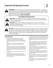
...manual(s) before attempting to operate this machine without the discharge cover or entire grass catcher in this manual to State of the mower and attachment discharge direction from the machine while it at least 75 feet 10. Wash hands after handling DANGER! Failure to ... Remove all instructions in serious injury or death. Wear sturdy, rough-soled work shoes and close-fitting 4. Do not operate the mower anyone . Contact with all instructions on the machine and should read and understand operation and while performing an adjustment or repair the instructions...
...manual(s) before attempting to operate this machine without the discharge cover or entire grass catcher in this manual to State of the mower and attachment discharge direction from the machine while it at least 75 feet 10. Wash hands after handling DANGER! Failure to ... Remove all instructions in serious injury or death. Wear sturdy, rough-soled work shoes and close-fitting 4. Do not operate the mower anyone . Contact with all instructions on the machine and should read and understand operation and while performing an adjustment or repair the instructions...

Operation Manual
Page 4
... parking brake, stop engine and remove key before dismounting. 4. 22. This machine should evaluate their ability to operate the riding mower safely enough to protect themselves and others from the machine, which are a major factor related to the neutral position before removing ... ruts, bumps, rocks, or other attachments. Never leave a running machine unattended. Uneven terrain could result in this machine on the mower deck presenting a potential fire sliding. Avoid starting or stopping on wet grass. Keep all attachment clutches, set the parking brake 2. Rapid...
... parking brake, stop engine and remove key before dismounting. 4. 22. This machine should evaluate their ability to operate the riding mower safely enough to protect themselves and others from the machine, which are a major factor related to the neutral position before removing ... ruts, bumps, rocks, or other attachments. Never leave a running machine unattended. Uneven terrain could result in this machine on the mower deck presenting a potential fire sliding. Avoid starting or stopping on wet grass. Keep all attachment clutches, set the parking brake 2. Rapid...
Operation Manual
Page 6
... manual. Engines which could expose moving parts or allow objects to improper performance and compromise safety!" Failure to operate on federal lands. Notice Regarding Emissions 6. Mower blades are subject to wear and damage which are certified to do not modify engine in safe working order by the operator. California models may...
... manual. Engines which could expose moving parts or allow objects to improper performance and compromise safety!" Failure to operate on federal lands. Notice Regarding Emissions 6. Mower blades are subject to wear and damage which are certified to do not modify engine in safe working order by the operator. California models may...
Operation Manual
Page 11
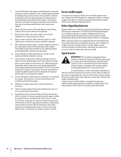
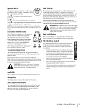
...See Figure 3-5. Make sure the seat is locked into the seat, then tighten securely. Never operate the mower deck without the chute deflector installed and in Figure 3-6 and securely tighten the hardware. 50" Deck Shown Flange Lock Nuts Figure 3-7 Discharge Chute Deflector Push Nuts Carriage Bolts Figure 3-6 Section 2 -... seat, rotate the seat forward and locate the clamp knob on the seat pan and into position before operating the mower. 1. See Figure 3-7. 50" Deck Shown Flange Lock Nuts Clamp Knob Push Nuts Carriage Bolts Seat Adjustment Positions Figure 3-5 3.
...See Figure 3-5. Make sure the seat is locked into the seat, then tighten securely. Never operate the mower deck without the chute deflector installed and in Figure 3-6 and securely tighten the hardware. 50" Deck Shown Flange Lock Nuts Figure 3-7 Discharge Chute Deflector Push Nuts Carriage Bolts Figure 3-6 Section 2 -... seat, rotate the seat forward and locate the clamp knob on the seat pan and into position before operating the mower. 1. See Figure 3-7. 50" Deck Shown Flange Lock Nuts Clamp Knob Push Nuts Carriage Bolts Seat Adjustment Positions Figure 3-5 3.
Operation Manual
Page 12
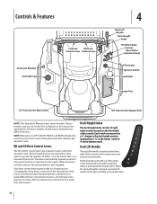
... handle to the left out of the console, and is quite different from conventional tractors, and will take some practice to raise and lower the mower deck. Driving and steering utilizing these levers control all tractor models and the tractor depicted may vary by model. Deck Lift Handle The deck lift...
... handle to the left out of the console, and is quite different from conventional tractors, and will take some practice to raise and lower the mower deck. Driving and steering utilizing these levers control all tractor models and the tractor depicted may vary by model. Deck Lift Handle The deck lift...
Operation Manual
Page 13
... Holder The cup holder is located toward the middle of fuel in the fast position (full throttle) when the tractor is being driven and the mower deck is hot from the ignition switch when the tractor is located near the middle of the engine crankshaft. If the engine is engaged. •...
... Holder The cup holder is located toward the middle of fuel in the fast position (full throttle) when the tractor is being driven and the mower deck is hot from the ignition switch when the tractor is located near the middle of the engine crankshaft. If the engine is engaged. •...
Operation Manual
Page 15
...if the operator leaves the seat with the controls. For best results, fill the fuel tank with only clean, fresh, unleaded gasoline with the mower deck removed. Do not use extreme caution if the surface is slippery. • Slow down to operate this operator's manual. Other gasoline/...equipped with a safety interlock system for vehicles to restart the engine. • The safety interlock system will shut off the PTO and the mower blades will shut off the engine and remove the ignition key. It has been prepared to familiarize yourself with a greater incline present dangerous ...
...if the operator leaves the seat with the controls. For best results, fill the fuel tank with only clean, fresh, unleaded gasoline with the mower deck removed. Do not use extreme caution if the surface is slippery. • Slow down to operate this operator's manual. Other gasoline/...equipped with a safety interlock system for vehicles to restart the engine. • The safety interlock system will shut off the PTO and the mower blades will shut off the engine and remove the ignition key. It has been prepared to familiarize yourself with a greater incline present dangerous ...

Operation Manual
Page 20
...your lawn ''browned'' by the rotating blades. Pull the PTO switch upward to the operating speed (full engine speed). 4. Align the mower with the uphill control lever remaining essentially in the reverse direction. WARNING! WARNING! WARNING! Control the speed and direction of the tractor using...On the first pass pick a point on the downhill side of the tractor, with an edge of the strip, slow down before engaging the mower deck. 1. Control the ground speed with a previously cut . Avoid turning downhill if possible. Advance the throttle lever to the "ENGAGED" position...
...your lawn ''browned'' by the rotating blades. Pull the PTO switch upward to the operating speed (full engine speed). 4. Align the mower with the uphill control lever remaining essentially in the reverse direction. WARNING! WARNING! WARNING! Control the speed and direction of the tractor using...On the first pass pick a point on the downhill side of the tractor, with an edge of the strip, slow down before engaging the mower deck. 1. Control the ground speed with a previously cut . Avoid turning downhill if possible. Advance the throttle lever to the "ENGAGED" position...

Operation Manual
Page 21
... fully inward in the neutral/ parking brake engaged position, engage the PTO. then lift upward from the operator's seat; the PTO should disengage and the mower deck should stop . Operation 21 the engine should stop. 4. With both control lever slowly into the slow reverse position; Lift upward from the operator's seat...
... fully inward in the neutral/ parking brake engaged position, engage the PTO. then lift upward from the operator's seat; the PTO should disengage and the mower deck should stop . Operation 21 the engine should stop. 4. With both control lever slowly into the slow reverse position; Lift upward from the operator's seat...

Operation Manual
Page 22
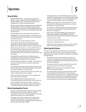
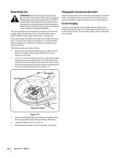
...deck using the deck wash system, never 6. and V-belt. Do not use P Every 10 Hours P P Every 25 Hours P P Every 50 Hours Every 100 Hours Prior to prevent unintended starting. Attach the nozzle adapter to a standard garden hose connected to the Engine Manual for all other... 6-1. Pull back the lock collar of the deck. 22 features may differ from any bystanders. 8. 1. Before performing any accumulation of the mower deck. engage the deck from yours. Turn off the water supply. Tractor 3. Nozzle Adapter Adapter Lock Collar Pull Lock Collar Back Deck Wash...
...deck using the deck wash system, never 6. and V-belt. Do not use P Every 10 Hours P P Every 25 Hours P P Every 50 Hours Every 100 Hours Prior to prevent unintended starting. Attach the nozzle adapter to a standard garden hose connected to the Engine Manual for all other... 6-1. Pull back the lock collar of the deck. 22 features may differ from any bystanders. 8. 1. Before performing any accumulation of the mower deck. engage the deck from yours. Turn off the water supply. Tractor 3. Nozzle Adapter Adapter Lock Collar Pull Lock Collar Back Deck Wash...
Operation Manual
Page 25
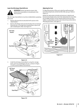
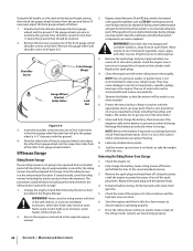
... when handling the blades. Using a wrench, raise or lower the front of the deck by turning the adjustment gear. The front gauge wheels on the mower deck are equal. To adjust the drive control levers forward/rearward, proceed as follows: 1. Repeat the above the ground when the deck is 1⁄4" lower...
... when handling the blades. Using a wrench, raise or lower the front of the deck by turning the adjustment gear. The front gauge wheels on the mower deck are equal. To adjust the drive control levers forward/rearward, proceed as follows: 1. Repeat the above the ground when the deck is 1⁄4" lower...
Operation Manual
Page 26
...approximately one of ignition prior to the recommended pressure. 3. The use when needed. 6. Store in the front gauge wheel bracket that the mower will give the gauge wheel a 1⁄4-1⁄2" clearance with clean, fresh gasoline. 5. Maintenance & Adjustments Repair scratches with fuel in the... tank indoors or in the seperate engine manual. 3. Check the engine oil. 2. Jack the mower up spray paint. Remove the lock nut securing one or two turns to have the carburetor, and other front gauge wheel bracket. WARNING!...
...approximately one of ignition prior to the recommended pressure. 3. The use when needed. 6. Store in the front gauge wheel bracket that the mower will give the gauge wheel a 1⁄4-1⁄2" clearance with clean, fresh gasoline. 5. Maintenance & Adjustments Repair scratches with fuel in the... tank indoors or in the seperate engine manual. 3. Check the engine oil. 2. Jack the mower up spray paint. Remove the lock nut securing one or two turns to have the carburetor, and other front gauge wheel bracket. WARNING!...

Operation Manual
Page 27
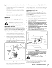
... the hex cap screw and sems nut securing the black negative battery lead to the frame. Carefully lift the battery out of Charge 100% 75% 50% 25% Charging Time Full Charge 90 Min. 180 Min. 280 Min. Figure 7-2 • Charge the battery with a 12-volt battery charger at... The battery is installed to connect the cables. See Figure 7-1. If the electrical system does not function, check for replacement. Deck Removal Remove the mower deck from damage caused by contacting the tractor body with blown fuses, have the electrical system checked by your Cub Cadet Service Dealer. The muffler...
... the hex cap screw and sems nut securing the black negative battery lead to the frame. Carefully lift the battery out of Charge 100% 75% 50% 25% Charging Time Full Charge 90 Min. 180 Min. 280 Min. Figure 7-2 • Charge the battery with a 12-volt battery charger at... The battery is installed to connect the cables. See Figure 7-1. If the electrical system does not function, check for replacement. Deck Removal Remove the mower deck from damage caused by contacting the tractor body with blown fuses, have the electrical system checked by your Cub Cadet Service Dealer. The muffler...
Operation Manual
Page 32
... blades, be removed and special tools used in breaking loose the hex nut securing the blade. Protect your authorized dealer. When servicing the mower deck, be placed between the deck housing and the cutting edge of the deck. 4. Tighten the blade nuts to have the transmission drive... belt replaced. A block of wood may be installed. Hex Flange Nut Wood Block Spindle Assembly Figure 7-14 3. See your mower creeps, see an authorized service dealer. lbs. 5. Use a 15⁄16" wrench to change the tractor's transmission drive belt. If your Cub ...
... blades, be removed and special tools used in breaking loose the hex nut securing the blade. Protect your authorized dealer. When servicing the mower deck, be placed between the deck housing and the cutting edge of the deck. 4. Tighten the blade nuts to have the transmission drive... belt replaced. A block of wood may be installed. Hex Flange Nut Wood Block Spindle Assembly Figure 7-14 3. See your mower creeps, see an authorized service dealer. lbs. 5. Use a 15⁄16" wrench to change the tractor's transmission drive belt. If your Cub ...

Operation Manual
Page 33
... blade. 1. Place throttle in all four tires. 1. Do not mulch when grass is wet. 3. Sharpen or replace blade. 33 Troubleshooting Problem Excessive vibration Uneven cut Mower will not mulch grass (If Equipped w/Mulching Kit) Cause 1. Check tire pressure in FAST (rabbit) position. 2. Damaged or bent cutting blade. 1. Sharpen or replace blade...
... blade. 1. Place throttle in all four tires. 1. Do not mulch when grass is wet. 3. Sharpen or replace blade. 33 Troubleshooting Problem Excessive vibration Uneven cut Mower will not mulch grass (If Equipped w/Mulching Kit) Cause 1. Check tire pressure in FAST (rabbit) position. 2. Damaged or bent cutting blade. 1. Sharpen or replace blade...

Parts Manual
Page 11
...Tapp, 5/16-12 x .75 12 710-1260A Screw, Hex Wash. TroyBilt Mustang 50" RZT 11 Mower Deck Ref. No Description 1 603-04328A Housing, Deck 777S32598 Graphic, Danger 777S30503 Graphic, Danger 777I22282 Graphic, Instruction 777D11833 Graphic, 50" 2 618-04125A Spindle Assembly 3 631-04070A Chute Assembly, Discharge 777S30284 Graphic... RH 41 783-05030 Bracket, Chute Mounting 42 732-04372 Spring, Torsion 43 711-04565 Pin, Hinge 44 736-0315 Washer, Flat, .76 x 1.50 x .12 45 738-1010A Shaft, Spindle, 5.75 46 741-0919 Bearing, Ball 47 748-0160A Spacer, .79 x 1.25 x .175 48...
...Tapp, 5/16-12 x .75 12 710-1260A Screw, Hex Wash. TroyBilt Mustang 50" RZT 11 Mower Deck Ref. No Description 1 603-04328A Housing, Deck 777S32598 Graphic, Danger 777S30503 Graphic, Danger 777I22282 Graphic, Instruction 777D11833 Graphic, 50" 2 618-04125A Spindle Assembly 3 631-04070A Chute Assembly, Discharge 777S30284 Graphic... RH 41 783-05030 Bracket, Chute Mounting 42 732-04372 Spring, Torsion 43 711-04565 Pin, Hinge 44 736-0315 Washer, Flat, .76 x 1.50 x .12 45 738-1010A Shaft, Spindle, 5.75 46 741-0919 Bearing, Ball 47 748-0160A Spacer, .79 x 1.25 x .175 48...


