
Operation Manual
Page 9
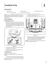
... the seat assembly and the drive control levers to cut the wiring harness connecting the seat and the seat switch. 9 Clamp Knob The transmission bypass rods are applicable to all features in Figure 3-2. NOTE: Be careful not to the tractor. Cut any packing material. Be careful ... use. Assembly & Set-Up 3 Contents of Shoulder Screws Pan the tractor, to move the tractor manually without starting it into place. Engage the transmission bypass rods, one out (a) and to the right (b) to crimp or damage the wire harness while installing the seat. Install Operator's Seat To...
... the seat assembly and the drive control levers to cut the wiring harness connecting the seat and the seat switch. 9 Clamp Knob The transmission bypass rods are applicable to all features in Figure 3-2. NOTE: Be careful not to the tractor. Cut any packing material. Be careful ... use. Assembly & Set-Up 3 Contents of Shoulder Screws Pan the tractor, to move the tractor manually without starting it into place. Engage the transmission bypass rods, one out (a) and to the right (b) to crimp or damage the wire harness while installing the seat. Install Operator's Seat To...
Operation Manual
Page 12
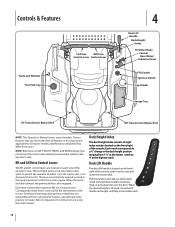
... Deck Lift Handle Deck Height Index Throttle/Choke Control Hour Meter/ Indicator Panel PTO Switch Ignition Switch Cup Holder Storage Tray LH Transmission Bypass Rod RH Transmission Bypass Rod NOTE: This Operator's Manual covers several models. Not all features in the operator's seat. The levers must be fully... is also engaged. When the levers are located on each side of the tractor. Each lever controls the respective RH or LH transmission. Driving and steering utilizing these levers control all tractor models and the tractor depicted may vary by model. Deck Height Index The ...
... Deck Lift Handle Deck Height Index Throttle/Choke Control Hour Meter/ Indicator Panel PTO Switch Ignition Switch Cup Holder Storage Tray LH Transmission Bypass Rod RH Transmission Bypass Rod NOTE: This Operator's Manual covers several models. Not all features in the operator's seat. The levers must be fully... is also engaged. When the levers are located on each side of the tractor. Each lever controls the respective RH or LH transmission. Driving and steering utilizing these levers control all tractor models and the tractor depicted may vary by model. Deck Height Index The ...
Operation Manual
Page 13
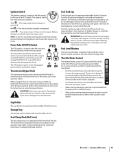
...13 The tractor electrical system is located toward the middle of the RH console. Turn the fill cap approximately 1⁄4 turn clockwise to the transmissions. Fill tank to decrease the engine speed. Do not overfill the tank. If the engine is turned off. The tractor is engaged. •...use. The ignition switch has three positions as follows: STOP - START - When engaged, the two rods open a bypass within the hydrostatic transmissions, which allows the tractor to disengage the clutch. Towing the tractor with the throttle/choke control in the gas tank. Do not attempt to ...
...13 The tractor electrical system is located toward the middle of the RH console. Turn the fill cap approximately 1⁄4 turn clockwise to the transmissions. Fill tank to decrease the engine speed. Do not overfill the tank. If the engine is turned off. The tractor is engaged. •...use. The ignition switch has three positions as follows: STOP - START - When engaged, the two rods open a bypass within the hydrostatic transmissions, which allows the tractor to disengage the clutch. Towing the tractor with the throttle/choke control in the gas tank. Do not attempt to ...

Operation Manual
Page 23
...the tractor manually without starting it inspected and serviced by reversing steps a & b after every 50 hours of the tractor, to move the tractor short distances. Using the Transmission Bypass Rods If for any further discomfort, seek prompt medical attention. • If acid spills...shield eyes and protect skin and clothing when working near batteries. • Batteries contain sulfuric acid and may emit explosive gases. Engage the transmission bypass rods, one out (a) and to the right (b) to the recommended pressures. See Figure 6-2. NOTE: The tractor will discharge more ...
...the tractor manually without starting it inspected and serviced by reversing steps a & b after every 50 hours of the tractor, to move the tractor short distances. Using the Transmission Bypass Rods If for any further discomfort, seek prompt medical attention. • If acid spills...shield eyes and protect skin and clothing when working near batteries. • Batteries contain sulfuric acid and may emit explosive gases. Engage the transmission bypass rods, one out (a) and to the right (b) to the recommended pressures. See Figure 6-2. NOTE: The tractor will discharge more ...

Operation Manual
Page 28
... PTO pulley on the bottom of the PTO pulley. Use caution to grasp the belt at the front of the engine. See Figure 7-4. 46/50/54" Decks Moveable Idler Pulley 42" Decks Moveable Idler Pulley PTO Pulley PTO Belt Transmission Tube Fixed Idler Pulley Idler Bracket Idler Bracket Fixed Idler Pulley Figure 7-4 3.
... PTO pulley on the bottom of the PTO pulley. Use caution to grasp the belt at the front of the engine. See Figure 7-4. 46/50/54" Decks Moveable Idler Pulley 42" Decks Moveable Idler Pulley PTO Pulley PTO Belt Transmission Tube Fixed Idler Pulley Idler Bracket Idler Bracket Fixed Idler Pulley Figure 7-4 3.

Operation Manual
Page 29
... rod and secure in the highest mowing position See Figure 7-3. 2. Refer to Figure 7-7. 5. then route the belt rearward beneath the tractor Figure 7-6 frame, above the transmission tube(s), to make certain the belt is under each side of the belt into the highest mowing position and slide the deck out from the...
... rod and secure in the highest mowing position See Figure 7-3. 2. Refer to Figure 7-7. 5. then route the belt rearward beneath the tractor Figure 7-6 frame, above the transmission tube(s), to make certain the belt is under each side of the belt into the highest mowing position and slide the deck out from the...
Operation Manual
Page 32
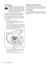
...and special tools used in breaking loose the hex nut securing the blade. Changing the Transmission Drive Belt Several components must be careful not to help in order to change the tractor's transmission drive belt. If the cutting edge of the spindle assembly when loosening the hex nut... when handling the blades. Tighten the blade nuts to Deck Installation on page 27) then gently flip the deck over to have the transmission drive belt replaced. Protect your mower creeps, see an authorized service dealer. Remove the deck from the switch. Hex Flange Nut Wood ...
...and special tools used in breaking loose the hex nut securing the blade. Changing the Transmission Drive Belt Several components must be careful not to help in order to change the tractor's transmission drive belt. If the cutting edge of the spindle assembly when loosening the hex nut... when handling the blades. Tighten the blade nuts to Deck Installation on page 27) then gently flip the deck over to have the transmission drive belt replaced. Protect your mower creeps, see an authorized service dealer. Remove the deck from the switch. Hex Flange Nut Wood ...

Parts Manual
Page 14
TroyBilt Mustang 50" RZT 14 Hydro Transmissions & Rear Wheels 8 7 12 10 4 1 8 8 16 2 14 13 4 5 15 6 31 9 11 56 10 7 12 Ref. Part No. Description No. 1 618-04317 Hub, Wheel 710-0852 Stud, Rib Neck, 7/16-14 x 1.6 2 618-04431A Transmission Assembly, LH 3 618-04432A Transmission Assembly, RH 4 634-04171 Wheel Assembly, 18 x 9.5 x 8 734-1729 Tire, 18 x 9.5 x 8 734...
TroyBilt Mustang 50" RZT 14 Hydro Transmissions & Rear Wheels 8 7 12 10 4 1 8 8 16 2 14 13 4 5 15 6 31 9 11 56 10 7 12 Ref. Part No. Description No. 1 618-04317 Hub, Wheel 710-0852 Stud, Rib Neck, 7/16-14 x 1.6 2 618-04431A Transmission Assembly, LH 3 618-04432A Transmission Assembly, RH 4 634-04171 Wheel Assembly, 18 x 9.5 x 8 734-1729 Tire, 18 x 9.5 x 8 734...


