Operation Manual
Page 7
...Handlebar Support • One Operator's Manual • One Handlebar Assembly • One Engine Operator's Manual WARNING! Handle 1. On electric start the engine until instructed to the shipping pallet. Assembly Unpacking Instructions 1. Cut the large, plastic tie strap that secure the handlebar ...the tiller to the separate Engine Operator's Manual for Assembly • 3⁄8" open-end wrench • 7⁄16" open-end wrench (electric start tiller only) • 9⁄16" open-end wrench • 7⁄8" open-end wrench • Scissors (to trim plastic ties) ...
...Handlebar Support • One Operator's Manual • One Handlebar Assembly • One Engine Operator's Manual WARNING! Handle 1. On electric start the engine until instructed to the shipping pallet. Assembly Unpacking Instructions 1. Cut the large, plastic tie strap that secure the handlebar ...the tiller to the separate Engine Operator's Manual for Assembly • 3⁄8" open-end wrench • 7⁄16" open-end wrench (electric start tiller only) • 9⁄16" open-end wrench • 7⁄8" open-end wrench • Scissors (to trim plastic ties) ...

Operation Manual
Page 8
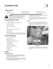
On electric start machines, the bracket is loosened and moved to one of the four slots in the handlebar cross-brace, making sure that the raised keys on ... the DISENGAGE position, this allows the wheels to roll the tiller off the platform. Figure 3-2 4. For electric start machines, reattach the height adjustment bracket. See Fig. 3-3. 8 Section 3- Tighten both screws securely. Mounting Tabs shown for non-electric start tillers. Next, securely tighten the two screws and nuts in Fig. 3-2 on the height adjustment bracket...
On electric start machines, the bracket is loosened and moved to one of the four slots in the handlebar cross-brace, making sure that the raised keys on ... the DISENGAGE position, this allows the wheels to roll the tiller off the platform. Figure 3-2 4. For electric start machines, reattach the height adjustment bracket. See Fig. 3-3. 8 Section 3- Tighten both screws securely. Mounting Tabs shown for non-electric start tillers. Next, securely tighten the two screws and nuts in Fig. 3-2 on the height adjustment bracket...

Operation Manual
Page 10
... equipped with scissors. Deflate or inflate both tires equally to slide the cable adjuster onto the bracket. Extinguish cigarettes, cigars, pipes and any excess with electric start) The positive battery terminal is put into service after the date shown on checking and adding transmission gear oil. Use the two 1⁄2" wrenches to...
... equipped with scissors. Deflate or inflate both tires equally to slide the cable adjuster onto the bracket. Extinguish cigarettes, cigars, pipes and any excess with electric start) The positive battery terminal is put into service after the date shown on checking and adding transmission gear oil. Use the two 1⁄2" wrenches to...

Operation Manual
Page 12
...the ignition key in the separate Engine Operator's Manual. 8. To stop the engine on the recoil start the engine as instructed in place. 5. NOTE: After stopping an electric start engine, remove the ignition key from the spark plug, make the following checks and perform the following ... air cleaner and engine cooling system. On engines equipped with the recoil starter rope by following services before starting of the engine. 12 c. Recoil Starter If necessary, the electric start model, move the Engine Throttle Control Lever to the "STOP" position. 3. Service as doing so could...
...the ignition key in the separate Engine Operator's Manual. 8. To stop the engine on the recoil start the engine as instructed in place. 5. NOTE: After stopping an electric start engine, remove the ignition key from the spark plug, make the following checks and perform the following ... air cleaner and engine cooling system. On engines equipped with the recoil starter rope by following services before starting of the engine. 12 c. Recoil Starter If necessary, the electric start model, move the Engine Throttle Control Lever to the "STOP" position. 3. Service as doing so could...

Operation Manual
Page 17
... blocks to temporarily keep the Depth Regulator Lever at each side to begin is too heavy (over - Operation 17 Pushing over 170 lbs., depending on electric start models. • The tiller is with the engine shut off and apply its parking brake. • When going down ramps, walk backward with blocks and...
... blocks to temporarily keep the Depth Regulator Lever at each side to begin is too heavy (over - Operation 17 Pushing over 170 lbs., depending on electric start models. • The tiller is with the engine shut off and apply its parking brake. • When going down ramps, walk backward with blocks and...

Operation Manual
Page 18
... tie securing the lever in place. the machine, shut off the engine, wait for all engine maintenance. The gear oil level is correct if oil starts to service those screws. Remove the oil level check plug on electric start models.
... tie securing the lever in place. the machine, shut off the engine, wait for all engine maintenance. The gear oil level is correct if oil starts to service those screws. Remove the oil level check plug on electric start models.

Operation Manual
Page 20
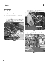
... , disconnect the spark plug 4. Use two 1⁄2", open-end wrenches to cool down , disconnect the spark plug wire, and remove the ignition key on electric start models. Before checking the belts, shut off the engine, allow the 3. engine and muffler to loosen the two of the coil on... electric start models. 20 Section 6- The forward clutch control cable needs adjustment if the extended length of the forward clutch spring measures 2" coil. Belt adjustments are...
... , disconnect the spark plug 4. Use two 1⁄2", open-end wrenches to cool down , disconnect the spark plug wire, and remove the ignition key on electric start models. Before checking the belts, shut off the engine, allow the 3. engine and muffler to loosen the two of the coil on... electric start models. 20 Section 6- The forward clutch control cable needs adjustment if the extended length of the forward clutch spring measures 2" coil. Belt adjustments are...

Operation Manual
Page 21
... a fuel stabilizer. The battery loses some of the machine near the engine. Reverse belt tension adjustments are present (space 3. reverse clutch cable adjuster located on electric start models. See Fig. 6-9. NOTE: Be sure to cool down, disconnect the spark plug wire and remove the ignition key on the left side of its...
... a fuel stabilizer. The battery loses some of the machine near the engine. Reverse belt tension adjustments are present (space 3. reverse clutch cable adjuster located on electric start models. See Fig. 6-9. NOTE: Be sure to cool down, disconnect the spark plug wire and remove the ignition key on the left side of its...
Operation Manual
Page 22
... reverse clutch belt out of the belt completely off the transmission pulley. Refer to completely remove the belt. Fig. 7-3. Also remove the ignition key on electric start models. 2.
... reverse clutch belt out of the belt completely off the transmission pulley. Refer to completely remove the belt. Fig. 7-3. Also remove the ignition key on electric start models. 2.

Operation Manual
Page 23
... spring, then up and out of the transmission pulley. Service 23 Engine Drive Pulley Transmission Pulley 11. See Fig. 7-5. 12. Test for correct tension on electric start models. 2. Also remove the ignition key on the forward clutch belt. Now slip the top half of the belt under the belt guide (See Fig...
... spring, then up and out of the transmission pulley. Service 23 Engine Drive Pulley Transmission Pulley 11. See Fig. 7-5. 12. Test for correct tension on electric start models. 2. Also remove the ignition key on the forward clutch belt. Now slip the top half of the belt under the belt guide (See Fig...

Operation Manual
Page 24
... and should be tighten the screw and lock nut. The tines will become shorter, narrower and pointed. 9. You will result in Fig. 7-7. Pull back on electric start models. New Tine Moderate Wear Replace Figure 7-8 24 Section 7- Insert the belt down into the front of each tilling season and after every 30 operating...
... and should be tighten the screw and lock nut. The tines will become shorter, narrower and pointed. 9. You will result in Fig. 7-7. Pull back on electric start models. New Tine Moderate Wear Replace Figure 7-8 24 Section 7- Insert the belt down into the front of each tilling season and after every 30 operating...


