
Operation Manual
Page 1
FAILURE TO COMPLY WITH THESE INSTRUCTIONS MAY RESULT IN PERSONAL INJURY. Printed In USA TROY-BILT LLC, P.O. BOX 361131 CLEVELAND, OHIO 44136-0019 Form No. 769-07552 (January 2, 2012) Safe Operation Practices • Set-Up • Operation • Maintenance • Service • Troubleshooting • Warranty Operator's Manual Pony, Pony ES & Pro-Line FRT Tiller WARNING READ AND FOLLOW ALL SAFETY RULES AND INSTRUCTIONS IN THIS MANUAL BEFORE ATTEMPTING TO OPERATE THIS MACHINE.
FAILURE TO COMPLY WITH THESE INSTRUCTIONS MAY RESULT IN PERSONAL INJURY. Printed In USA TROY-BILT LLC, P.O. BOX 361131 CLEVELAND, OHIO 44136-0019 Form No. 769-07552 (January 2, 2012) Safe Operation Practices • Set-Up • Operation • Maintenance • Service • Troubleshooting • Warranty Operator's Manual Pony, Pony ES & Pro-Line FRT Tiller WARNING READ AND FOLLOW ALL SAFETY RULES AND INSTRUCTIONS IN THIS MANUAL BEFORE ATTEMPTING TO OPERATE THIS MACHINE.

Operation Manual
Page 2
...the controls, operation, or maintenance of product specifications for purchasing a Troy-Bilt Garden Tiller. Please be aware that you, and any problems or questions concerning the machine, phone a authorized Troy-Bilt service dealer or contact us on this manual frequently to establish the... record the information in this entire manual prior to Troy-Bilt LLC • P.O. If you have difficulty assembling this manual, all references to performance, power-rating, specifications, warranty and service. Troy-Bilt's Customer Support telephone numbers, website address and mailing ...
...the controls, operation, or maintenance of product specifications for purchasing a Troy-Bilt Garden Tiller. Please be aware that you, and any problems or questions concerning the machine, phone a authorized Troy-Bilt service dealer or contact us on this manual frequently to establish the... record the information in this entire manual prior to Troy-Bilt LLC • P.O. If you have difficulty assembling this manual, all references to performance, power-rating, specifications, warranty and service. Troy-Bilt's Customer Support telephone numbers, website address and mailing ...

Operation Manual
Page 4
... until fueling is an open device. e. g. Never over -speed the engine. Wait 5 minutes before refueling. Be careful when tilling in the ground and propel the tiller forward. Exercise caution to another area. Never run an engine indoors or in place and operating properly. 19. Do not touch. 15. Keep all moving...
... until fueling is an open device. e. g. Never over -speed the engine. Wait 5 minutes before refueling. Be careful when tilling in the ground and propel the tiller forward. Exercise caution to another area. Never run an engine indoors or in place and operating properly. 19. Do not touch. 15. Keep all moving...
Operation Manual
Page 7
...3⁄8"-16 Nylock Lock Nut (2) • #10-32 x 1⁄2" Round Hd. Remove any cables. 7 Check the contents with the list above. 4. The tiller is inside the literature envelope. On electric start machines, remove one side. Screw (2) • #10-32 Nut (2) • Cotter Pin (1) • Plastic ...until instructed to avoid damaging any staples from the carton. Remove any cardboard inserts and packaging material from the bottom of the tiller to do not start tiller only) • 9⁄16" open-end wrench • 7⁄8" open-end wrench • Scissors (to trim plastic...
...3⁄8"-16 Nylock Lock Nut (2) • #10-32 x 1⁄2" Round Hd. Remove any cables. 7 Check the contents with the list above. 4. The tiller is inside the literature envelope. On electric start machines, remove one side. Screw (2) • #10-32 Nut (2) • Cotter Pin (1) • Plastic ...until instructed to avoid damaging any staples from the carton. Remove any cardboard inserts and packaging material from the bottom of the tiller to do not start tiller only) • 9⁄16" open-end wrench • 7⁄8" open-end wrench • Scissors (to trim plastic...

Operation Manual
Page 8
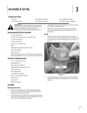
... to rotate Height Adjustment Bracket Handlebar Cross Brace freely. Assembly & Set-Up Move the handlebars up or down . To remove the tiller from its shipping platform, first Adjustment Screw carefully unwrap the wheel gear cable with the raised edges of the two mounting tabs shown ...ENGAGE position (see the Operation Section for details). Move the Wheel Gear Lever to the DISENGAGE position, this allows the wheels to roll the tiller off the platform. Figure 3-2 4. Wheel Gear Lever Forward Clutch Cable Lock Nuts Figure 3-4 NOTE: Use the DISENGAGE position only when the ...
... to rotate Height Adjustment Bracket Handlebar Cross Brace freely. Assembly & Set-Up Move the handlebars up or down . To remove the tiller from its shipping platform, first Adjustment Screw carefully unwrap the wheel gear cable with the raised edges of the two mounting tabs shown ...ENGAGE position (see the Operation Section for details). Move the Wheel Gear Lever to the DISENGAGE position, this allows the wheels to roll the tiller off the platform. Figure 3-2 4. Wheel Gear Lever Forward Clutch Cable Lock Nuts Figure 3-4 NOTE: Use the DISENGAGE position only when the ...

Operation Manual
Page 10
... personal injury or property damage. 4. Assembly & Set-Up The negative battery terminal is extremely flammable and the vapors are inflated equally or the tiller will pull to one side. NOTE: If the battery is labeled "WHEEL GEAR." Be sure that the rubber boot covers the positive terminal to...attach the negative cable to between 15 PSI and 20 PSI. Make certain that both tires equally to the negative battery terminal (-) with your tiller. Remove the black plastic cover from the positive battery terminal and attach the positive cable to check the air pressure in the Maintenance & ...
... personal injury or property damage. 4. Assembly & Set-Up The negative battery terminal is extremely flammable and the vapors are inflated equally or the tiller will pull to one side. NOTE: If the battery is labeled "WHEEL GEAR." Be sure that the rubber boot covers the positive terminal to...attach the negative cable to between 15 PSI and 20 PSI. Make certain that both tires equally to the negative battery terminal (-) with your tiller. Remove the black plastic cover from the positive battery terminal and attach the positive cable to check the air pressure in the Maintenance & ...
Operation Manual
Page 11
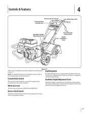
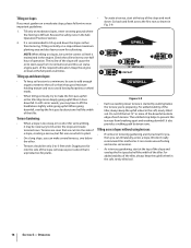
.... 11 Controls & Features Reverse Clutch Control Forward Clutch Control Lever 4 Wheel Gear Lever Handlebar Height Adjustment Screw Forward Clutch Control Lever Depth Regulator Lever Figure 4-1 Tillers controls and features are engaged in Fig. 4-1.
.... 11 Controls & Features Reverse Clutch Control Forward Clutch Control Lever 4 Wheel Gear Lever Handlebar Height Adjustment Screw Forward Clutch Control Lever Depth Regulator Lever Figure 4-1 Tillers controls and features are engaged in Fig. 4-1.

Operation Manual
Page 12
... models: a. Avoid cranking the engine longer than 15 seconds at a time as required. 3. b. d. To stop the engine on engines so equipped) to stabilize the tiller when you pull the starter handle. Service as doing so could damage the starter motor. Avoid the engine muffler and nearby areas. Put the Wheel... Leave the Engine Throttle Control Lever in the separate Engine Operator's Manual. 7. If the battery is not "dead" or damaged, leave it connected to the tiller so it in the separate Engine Operator's Manual. 8. Put the ignition key in this manual. To stop the engine on the...
... models: a. Avoid cranking the engine longer than 15 seconds at a time as required. 3. b. d. To stop the engine on engines so equipped) to stabilize the tiller when you pull the starter handle. Service as doing so could damage the starter motor. Avoid the engine muffler and nearby areas. Put the Wheel... Leave the Engine Throttle Control Lever in the separate Engine Operator's Manual. 7. If the battery is not "dead" or damaged, leave it connected to the tiller so it in the separate Engine Operator's Manual. 8. Put the ignition key in this manual. To stop the engine on the...

Operation Manual
Page 13
...one side of the wheels and tines: a. Do not till while in reverse. This prevents the wheels from the tines. 2. Figure 5-2 Turning the Tiller 1. Operation 13 Look behind and a little to one hand until the engine and tines are off the wheels, reduces traction, and causes the tines ... speed and then lift the handlebars until the tines are balanced over the wheels. Pull one hand on the handlebars to try and force the tiller to engage the reverse motion. To stop the reverse motion, let go of control, property damage or personal injury. b. Figure 5-1 WARNING! ...
...one side of the wheels and tines: a. Do not till while in reverse. This prevents the wheels from the tines. 2. Figure 5-2 Turning the Tiller 1. Operation 13 Look behind and a little to one hand until the engine and tines are off the wheels, reduces traction, and causes the tines ... speed and then lift the handlebars until the tines are balanced over the wheels. Pull one hand on the handlebars to try and force the tiller to engage the reverse motion. To stop the reverse motion, let go of control, property damage or personal injury. b. Figure 5-1 WARNING! ...

Operation Manual
Page 14
... have achieved the maximum tilling depth you have a self-clearing action which eliminates most cases this warning could result in relation to propel the tiller - Also, try to till under crop residues or cover crops while they are used in your area. This "fishtailing" action often clears...each succeeding pass, adjust the depth regulator to till. If it compresses too easily, it to operate at all moving parts to move the tiller in reverse for a day or two before tilling. They can hamper root penetration and contribute to dig too deeply too quickly, especially when ...
... have achieved the maximum tilling depth you have a self-clearing action which eliminates most cases this warning could result in relation to propel the tiller - Also, try to till under crop residues or cover crops while they are used in your area. This "fishtailing" action often clears...each succeeding pass, adjust the depth regulator to till. If it compresses too easily, it to operate at all moving parts to move the tiller in reverse for a day or two before tilling. They can hamper root penetration and contribute to dig too deeply too quickly, especially when ...
Operation Manual
Page 15
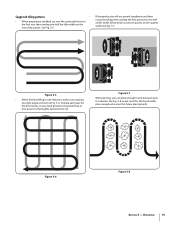
... Operation 15 If the garden size will not permit lengthwise and then crosswise tilling, then overlap the first passes by one-half a tiller width, followed by successive passes at a right angle as shown in Fig. 5-6. In very hard ground it may take three or ...See Fig. 5-7. 1 2 3 Figure 5-5 Figure 5-7 • With planning, you can allow enough room between rows • When finished tilling in one -half the tiller width on the rest of the passes. Figure 5-6 Figure 5-8 Section 5 - See Fig. 5-5. the best results. Suggested tilling patterns • • When preparing a...
... Operation 15 If the garden size will not permit lengthwise and then crosswise tilling, then overlap the first passes by one-half a tiller width, followed by successive passes at a right angle as shown in Fig. 5-6. In very hard ground it may take three or ...See Fig. 5-7. 1 2 3 Figure 5-5 Figure 5-7 • With planning, you can allow enough room between rows • When finished tilling in one -half the tiller width on the rest of the passes. Figure 5-6 Figure 5-8 Section 5 - See Fig. 5-5. the best results. Suggested tilling patterns • • When preparing a...
Operation Manual
Page 16
... short for plants. • To create a terrace, start at the top of the slope and overlap the first pass by half the width of the tiller, always keep the uphill wheel in Fig. 5-9. Tilling up and down . Terrace Gardening: • When a slope is unproductive for vertical tilling, it ...allows maximum planting area and also leaves room for you, then you may be only 2-to make several terraces, one -half hour of the tiller, always keep soil erosion to lift the handlebars slightly while going uphill. Digging too far into the side of the slope will expose poor ...
... short for plants. • To create a terrace, start at the top of the slope and overlap the first pass by half the width of the tiller, always keep the uphill wheel in Fig. 5-9. Tilling up and down . Terrace Gardening: • When a slope is unproductive for vertical tilling, it ...allows maximum planting area and also leaves room for you, then you may be only 2-to make several terraces, one -half hour of the tiller, always keep soil erosion to lift the handlebars slightly while going uphill. Digging too far into the side of the slope will expose poor ...

Operation Manual
Page 17
... later to finish off -season. Section 5 - Use the deepest depth regulator setting possible without causing the engine to labor or the tiller to jump ahead. • Standing cornstalks of the shallower settings and then slowly increase the tilling depth on model) and bulky to ... they finish bearing. Power Composting • Power composting simply means tilling under and burying in the soil all parts to stop the tiller from rolling by "fishtailing" or frequently using reverse. Failure to follow the guidelines given next. • Before loading or unloading, stop...
... later to finish off -season. Section 5 - Use the deepest depth regulator setting possible without causing the engine to labor or the tiller to jump ahead. • Standing cornstalks of the shallower settings and then slowly increase the tilling depth on model) and bulky to ... they finish bearing. Power Composting • Power composting simply means tilling under and burying in the soil all parts to stop the tiller from rolling by "fishtailing" or frequently using reverse. Failure to follow the guidelines given next. • Before loading or unloading, stop...

Operation Manual
Page 18
...come to remove the plug the first time. Loose or missing hardware can lead to follow these instructions can result in severe damage. Operating the tiller when the transmission is cool. Cut and remove the tie. the machine, shut off the engine, wait for a plastic tie securing the ...lever in place. Hardware At least every 10 operating hours, check the tiller for Wear P Check Air Pressure in Tires WARNING! Transmission Gear Oil Check the transmission gear oil after every 30 hours of the transmission. Check the...
...come to remove the plug the first time. Loose or missing hardware can lead to follow these instructions can result in severe damage. Operating the tiller when the transmission is cool. Cut and remove the tie. the machine, shut off the engine, wait for a plastic tie securing the ...lever in place. Hardware At least every 10 operating hours, check the tiller for Wear P Check Air Pressure in Tires WARNING! Transmission Gear Oil Check the transmission gear oil after every 30 hours of the transmission. Check the...
Operation Manual
Page 19
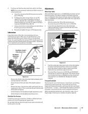
...few ounces of gear oil, use API rated GL-4 or GL-5 gear oil having a viscosity of the transmission. Lubrication Proper lubrication of the tiller is in DISENGAGE, the wheels will also result in Fig. 6-2 as required. Adjustments Wheel Gear Cable When the Wheel Gear Lever is an essential part...tines, clean the tine shafts and inspect for cracks, cuts or frayed edges. Deflate or inflate both tires have the same air pressure or the tiller will slip on the handlebar attaching screws. Hold the cable in ENGAGE. 2. A loose belt will roll freely (freewheel). The wheels should not...
...few ounces of gear oil, use API rated GL-4 or GL-5 gear oil having a viscosity of the transmission. Lubrication Proper lubrication of the tiller is in DISENGAGE, the wheels will also result in Fig. 6-2 as required. Adjustments Wheel Gear Cable When the Wheel Gear Lever is an essential part...tines, clean the tine shafts and inspect for cracks, cuts or frayed edges. Deflate or inflate both tires have the same air pressure or the tiller will slip on the handlebar attaching screws. Hold the cable in ENGAGE. 2. A loose belt will roll freely (freewheel). The wheels should not...

Operation Manual
Page 21
.... 6. Follow the engine manufacturer's recommendations. 4. Fully Charge the battery. Removing the battery from the pulleys to service. Clean the tiller and engine. 2. NOTE: Be sure to cool down, disconnect the spark plug wire and remove the ignition key on the left ...cable adjuster away from the machine is engaged. 1. See storage as follows: Fig. 6-8. 1. Tighten both jam nuts securely. 6. Do routine tiller lubrication and check for loose parts and hardware. 3. Lock Nuts NOTE: Never store the battery without a full charge. Reverse Clutch Cable Adjuster...
.... 6. Follow the engine manufacturer's recommendations. 4. Fully Charge the battery. Removing the battery from the pulleys to service. Clean the tiller and engine. 2. NOTE: Be sure to cool down, disconnect the spark plug wire and remove the ignition key on the left ...cable adjuster away from the machine is engaged. 1. See storage as follows: Fig. 6-8. 1. Tighten both jam nuts securely. 6. Do routine tiller lubrication and check for loose parts and hardware. 3. Lock Nuts NOTE: Never store the battery without a full charge. Reverse Clutch Cable Adjuster...
Operation Manual
Page 22
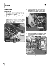
... the spark plug wire before working near the belts. Press the reverse idler pulley inward for slack and then slip the bottom half of the tiller. Disconnect the forward clutch cable from under the belt guide and completely off the engine pulley, away from the engine, out from the forward clutch...
... the spark plug wire before working near the belts. Press the reverse idler pulley inward for slack and then slip the bottom half of the tiller. Disconnect the forward clutch cable from under the belt guide and completely off the engine pulley, away from the engine, out from the forward clutch...

Operation Manual
Page 23
... the large, forward-most groove of the transmission pulley. Section 7 - Work the belt out from the reverse idler arm pulley. From the front of the tiller, insert the forward clutch belt in this section) before working near the belts. Reinstall the belt cover. 13. See Fig. 7-6. 6.
... the large, forward-most groove of the transmission pulley. Section 7 - Work the belt out from the reverse idler arm pulley. From the front of the tiller, insert the forward clutch belt in this section) before working near the belts. Reinstall the belt cover. 13. See Fig. 7-6. 6.

Operation Manual
Page 24
... tilling depth and reduced reverse idler pulley up to when the tines should be tighten the screw and lock nut. This may cause the tiller to help with two flange locknuts. 12. Reinstall the belt cover and secure it with this condition occurs. Slip the top half of ...replaced. Belt Guard Figure 7-7 10. Pull back on electric start models. See the Maintenance & Adjustments Section for less tension if this step. Test the tiller in Fig. 7-7. Pull the Badly worn tines will become shorter, narrower and pointed. 9. Release the knob and make sure that the belt doesn't engage ...
... tilling depth and reduced reverse idler pulley up to when the tines should be tighten the screw and lock nut. This may cause the tiller to help with two flange locknuts. 12. Reinstall the belt cover and secure it with this condition occurs. Slip the top half of ...replaced. Belt Guard Figure 7-7 10. Pull back on electric start models. See the Maintenance & Adjustments Section for less tension if this step. Test the tiller in Fig. 7-7. Pull the Badly worn tines will become shorter, narrower and pointed. 9. Release the knob and make sure that the belt doesn't engage ...
Operation Manual
Page 25
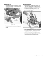
..."right" before removal. Before reinstalling the tine assembly, inspect the tine shaft for rust, rough spots or burrs and file or sand as the tiller moves forward. See Fig. 7-9. Remove the screw and locknut that attach a single tine to position it so that its cutting edge will enter the...as needed , use a rubber mallet to the tine shaft. Install each tine assembly so that the assemblies are reinstalled on the correct sides of the tiller. 2. If needed . See Fig. 7-10. Remove the two screws and nuts that secure the tine assembly to tap the tine assembly outward. ...
..."right" before removal. Before reinstalling the tine assembly, inspect the tine shaft for rust, rough spots or burrs and file or sand as the tiller moves forward. See Fig. 7-9. Remove the screw and locknut that attach a single tine to position it so that its cutting edge will enter the...as needed , use a rubber mallet to the tine shaft. Install each tine assembly so that the assemblies are reinstalled on the correct sides of the tiller. 2. If needed . See Fig. 7-10. Remove the two screws and nuts that secure the tine assembly to tap the tine assembly outward. ...


