
Operation Manual
Page 15
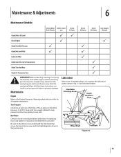
...for loose or missing hardware after every 10 operating hours and tighten or replace (as needed) before using tiller Be sure to check the screws underneath the tiller hood that secure the transmission cover and the Depth Regulator Lever to follow these instructions can result in serious... 5 Hours Every 10 Hours Every 30 Hours See Engine Manual Check Motor Oil Level PP Clean Engine P P Check Drive Belt Tension P P Check Nuts and Bolts P P Lubricate Tiller P Check Gear Oil Level in Transmission P Check Tines for all moving parts to come to the Engine Operator's Manual packed...
...for loose or missing hardware after every 10 operating hours and tighten or replace (as needed) before using tiller Be sure to check the screws underneath the tiller hood that secure the transmission cover and the Depth Regulator Lever to follow these instructions can result in serious... 5 Hours Every 10 Hours Every 30 Hours See Engine Manual Check Motor Oil Level PP Clean Engine P P Check Drive Belt Tension P P Check Nuts and Bolts P P Lubricate Tiller P Check Gear Oil Level in Transmission P Check Tines for all moving parts to come to the Engine Operator's Manual packed...
Operation Manual
Page 17
.... Badly worn tines will enable the belt to fall under organic matter. Install each tilling season and after every 30 operating hours. The tines can be replaced either individually or as the tiller moves forward. The procedure requires average mechanical ability and commonly available tools. When installing a single tine, be sure to...
.... Badly worn tines will enable the belt to fall under organic matter. Install each tilling season and after every 30 operating hours. The tines can be replaced either individually or as the tiller moves forward. The procedure requires average mechanical ability and commonly available tools. When installing a single tine, be sure to...

Operation Manual
Page 24
... above , given by this warranty provide the sole and exclusive remedy arising from defects in material and workmanship for the life of the tiller, to obtain warranty coverage. C This limited warranty shall only apply if this product has been operated and maintained in accordance with the Operator.... Box 361131, Cleveland, Ohio 44136-0019, or call 1-800-668-1238 or log on the date of charge, any product, shall bind Troy-Bilt. Belts are warranted to new merchandise purchased and used in the United States and/or its option, repair or replace, free of the attachment's original ...
... above , given by this warranty provide the sole and exclusive remedy arising from defects in material and workmanship for the life of the tiller, to obtain warranty coverage. C This limited warranty shall only apply if this product has been operated and maintained in accordance with the Operator.... Box 361131, Cleveland, Ohio 44136-0019, or call 1-800-668-1238 or log on the date of charge, any product, shall bind Troy-Bilt. Belts are warranted to new merchandise purchased and used in the United States and/or its option, repair or replace, free of the attachment's original ...
Service Manual
Page 8
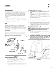
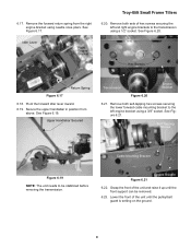
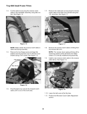
...Forward Idler Lever Forward Clutch Cable Clutch Cable Z Fitting Hex Jam Nut Figure 3.5 3.6. Remove the hex flange screw and large flat washer securing the belt cover to the lower cable mounting bracket using a 3/8" wrench and a 7/16" wrench. See Figure 3.6. Hex Flange Screw Figure 3.8 3.9. See Figure ... work area. Slide the forward clutch cable out of the forward clutch cable will not fit through the belt cover. Troy-Bilt Small Frame Tillers 3.5. Remove the lower cable tie securing the forward clutch cable to the lower handlebar using a 3/8" socket. See Figure 3.5.
...Forward Idler Lever Forward Clutch Cable Clutch Cable Z Fitting Hex Jam Nut Figure 3.5 3.6. Remove the hex flange screw and large flat washer securing the belt cover to the lower cable mounting bracket using a 3/8" wrench and a 7/16" wrench. See Figure 3.6. Hex Flange Screw Figure 3.8 3.9. See Figure ... work area. Slide the forward clutch cable out of the forward clutch cable will not fit through the belt cover. Troy-Bilt Small Frame Tillers 3.5. Remove the lower cable tie securing the forward clutch cable to the lower handlebar using a 3/8" socket. See Figure 3.5.
Service Manual
Page 9
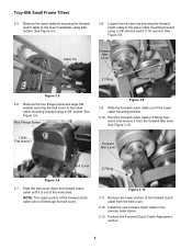
... a 3/8" socket. Remove the spark plug boot from the spark plug and ground it is out of the work area. Hex Flange Screw Large Flat Washer Belt Cover Clutch Cable Figure 4.4 4.5. Spark Plug Troy-Bilt Small Frame Tillers 4.4. See Figure 4.4. Belt Transmission Pulley Figure 4.2 4.3. See Figure 4.2. DRIVE...
... a 3/8" socket. Remove the spark plug boot from the spark plug and ground it is out of the work area. Hex Flange Screw Large Flat Washer Belt Cover Clutch Cable Figure 4.4 4.5. Spark Plug Troy-Bilt Small Frame Tillers 4.4. See Figure 4.4. Belt Transmission Pulley Figure 4.2 4.3. See Figure 4.2. DRIVE...
Service Manual
Page 10
... flange screw and large flat washer securing the belt cover to the engine. Lower Hook Figure 5.5 NOTE: There are two holes at the bottom of the return spring from the right engine bracket using needle nose pliers. Troy-Bilt Small Frame Tillers 5. See Figure 5.1. Remove the upper hook ...of the forward idler lever. Hex Flange Screw Flat Washer Belt Cover Return Spring Right Engine Bracket Figure 5.4 5.5. Remove the lower hook of ...
... flange screw and large flat washer securing the belt cover to the engine. Lower Hook Figure 5.5 NOTE: There are two holes at the bottom of the return spring from the right engine bracket using needle nose pliers. Troy-Bilt Small Frame Tillers 5. See Figure 5.1. Remove the upper hook ...of the forward idler lever. Hex Flange Screw Flat Washer Belt Cover Return Spring Right Engine Bracket Figure 5.4 5.5. Remove the lower hook of ...

Service Manual
Page 11
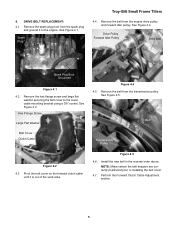
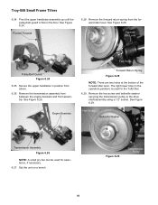
...idler lever. 6.4. Remove both hex flange screws securing the hood brackets to the transmission assembly using a 3/8" socket. Troy-Bilt Small Frame Tillers 6. tion through forward drive belt removal, prior to the lower cable mounting bracket using a 1/2" socket and wrench. performing this section. Pivot the ...Screw Figure 6.10 6.11. Hex Flange Screws Self Tapping Hex Flange Screws Figure 6.6 Hood Brackets Figure 6.11 7 onto it from the belt cover. 6.5. See Figure 6.10. Remove the lower portion of the lower cable mounting bracket. 6.3. See Figure 6.6. See Figure 6.11....
...idler lever. 6.4. Remove both hex flange screws securing the hood brackets to the transmission assembly using a 3/8" socket. Troy-Bilt Small Frame Tillers 6. tion through forward drive belt removal, prior to the lower cable mounting bracket using a 1/2" socket and wrench. performing this section. Pivot the ...Screw Figure 6.10 6.11. Hex Flange Screws Self Tapping Hex Flange Screws Figure 6.6 Hood Brackets Figure 6.11 7 onto it from the belt cover. 6.5. See Figure 6.10. Remove the lower portion of the lower cable mounting bracket. 6.3. See Figure 6.6. See Figure 6.11....
Service Manual
Page 13
... the front of the unit and raise it up until the pulley/belt guard is setting on the ground. 9 Idler Lever Right Engine Bracket Hex Screws Return Spring Figure 6.17 6.18. Secure the upper handlebar in position from the right engine bracket using a 1/2" socket. 6.17. Troy-Bilt Small Frame Tillers 6.20. See Figure 6.19.
... the front of the unit and raise it up until the pulley/belt guard is setting on the ground. 9 Idler Lever Right Engine Bracket Hex Screws Return Spring Figure 6.17 6.18. Secure the upper handlebar in position from the right engine bracket using a 1/2" socket. 6.17. Troy-Bilt Small Frame Tillers 6.20. See Figure 6.19.
Service Manual
Page 14
Troy-Bilt Small Frame Tillers 6.24. Pivot the upper handlebar assembly up until the pulley/belt guard is used for the Tuffy tiller. 6.29. See Figure 6.26. See Figure 6.29. Set the unit on the floor. Remove the forward return spring from between the engine brackets and front .... Remove the hex screw and belleville washer securing the transmission pulley to the drive shaft assembly using a 1/2" socket. Pivoted Forward 6.28. Forward Idle Lever Pulley/Belt Guard Figure 6.24 6.25. The right lower hole (in position from above. 6.26.
Troy-Bilt Small Frame Tillers 6.24. Pivot the upper handlebar assembly up until the pulley/belt guard is used for the Tuffy tiller. 6.29. See Figure 6.26. See Figure 6.29. Set the unit on the floor. Remove the forward return spring from between the engine brackets and front .... Remove the hex screw and belleville washer securing the transmission pulley to the drive shaft assembly using a 1/2" socket. Pivoted Forward 6.28. Forward Idle Lever Pulley/Belt Guard Figure 6.24 6.25. The right lower hole (in position from above. 6.26.
Service Manual
Page 38
... cable tied during assembly. 1.9. Install a new reverse clutch cable in the reverse order above. Hex Screw Belt Cover Reverse Clutch Cable Figure 1.5 1.6. Troy-Bilt Small Frame Tillers 1.4. See Figure 1.7. Perform the Reverse Clutch Cable Adjustment section. 34 See Figure 1.5. Belt Cover Bracket Inside Jam Nut Reverse Clutch Cable Jam Nut Figure 1.7 1.8. Flat Washer 1.7. NOTE: The...
... cable tied during assembly. 1.9. Install a new reverse clutch cable in the reverse order above. Hex Screw Belt Cover Reverse Clutch Cable Figure 1.5 1.6. Troy-Bilt Small Frame Tillers 1.4. See Figure 1.7. Perform the Reverse Clutch Cable Adjustment section. 34 See Figure 1.5. Belt Cover Bracket Inside Jam Nut Reverse Clutch Cable Jam Nut Figure 1.7 1.8. Flat Washer 1.7. NOTE: The...
Service Manual
Page 39
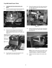
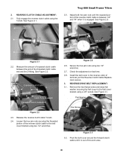
... the threaded portion of the work area. 35 Secure the hex jam nuts using the T-knob. See Figure 3.1. Pivot the belt cover around the forward clutch cable until the exposed portion of removal, per the Reverse Clutch Cable Replacement section. 3. Adjust both... between the end of the threaded clutch cable end and the Z-fitting. REVERSE DRIVE BELT REPLACEMENT: 3.1. REVERSE CLUTCH CABLE ADJUSTMENT: 2.1. Check the adjustment on last time. 2.8. Pull Out Troy-Bilt Small Frame Tillers 2.5. Measure the amount of exposed clutch cable between 1/8" and 1/4" when it is engaged...
... the threaded portion of the work area. 35 Secure the hex jam nuts using the T-knob. See Figure 3.1. Pivot the belt cover around the forward clutch cable until the exposed portion of removal, per the Reverse Clutch Cable Replacement section. 3. Adjust both... between the end of the threaded clutch cable end and the Z-fitting. REVERSE DRIVE BELT REPLACEMENT: 3.1. REVERSE CLUTCH CABLE ADJUSTMENT: 2.1. Check the adjustment on last time. 2.8. Pull Out Troy-Bilt Small Frame Tillers 2.5. Measure the amount of exposed clutch cable between 1/8" and 1/4" when it is engaged...

Service Manual
Page 40
...Lock Nut Figure 3.4 3.5. Remove all four self-tapping screws securing the pulley/belt guard to the left frame rail. Reverse Clutch Cable Reverse Idler Arm Z-Fitting Reverse Drive Belt Belt Guide Figure 3.3 NOTE: The reverse return spring will drop off its anchoring position... brackets using a 1/2" socket and wrench. Remove the pulley/belt guard. 36 Loosen the lock nut securing the reverse idler pulley belt guide in position using a 3/8" socket and wrench. See Figure 3.3. 3.4. Troy-Bilt Small Frame Tillers 3.3. Remove the reverse clutch cable's Z-fitting from the reverse...
...Lock Nut Figure 3.4 3.5. Remove all four self-tapping screws securing the pulley/belt guard to the left frame rail. Reverse Clutch Cable Reverse Idler Arm Z-Fitting Reverse Drive Belt Belt Guide Figure 3.3 NOTE: The reverse return spring will drop off its anchoring position... brackets using a 1/2" socket and wrench. Remove the pulley/belt guard. 36 Loosen the lock nut securing the reverse idler pulley belt guide in position using a 3/8" socket and wrench. See Figure 3.3. 3.4. Troy-Bilt Small Frame Tillers 3.3. Remove the reverse clutch cable's Z-fitting from the reverse...
Service Manual
Page 41
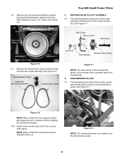
..., for the reverse idler, is installed inside -out on the transmission pulley. 37 Transmission Pulley Inside-Out Reverse Drive Belt Forward Drive Belt Lock Nut Reverse Idler Pulley Flat Washers Figure 4.1 NOTE: The open center of the transmission pulley. REVERSE IDLER PULLEY ASSEMBLY: 4.1. See Figure 5.1....3.8. Remove the hex screw and belleville washer securing the transmission pulley to the drive shaft assembly using a 1/2" socket. Install a new reverse drive belt in position before installing the transmission pulley. 3.10. See Figure 3.9. Troy-Bilt Small Frame Tillers 4.
..., for the reverse idler, is installed inside -out on the transmission pulley. 37 Transmission Pulley Inside-Out Reverse Drive Belt Forward Drive Belt Lock Nut Reverse Idler Pulley Flat Washers Figure 4.1 NOTE: The open center of the transmission pulley. REVERSE IDLER PULLEY ASSEMBLY: 4.1. See Figure 5.1....3.8. Remove the hex screw and belleville washer securing the transmission pulley to the drive shaft assembly using a 1/2" socket. Install a new reverse drive belt in position before installing the transmission pulley. 3.10. See Figure 3.9. Troy-Bilt Small Frame Tillers 4.

