Owners Manual
Page 2
MRF-200 Installation Manual © 2003 Universal Remote Control, Inc. SHALL NOT BE LIABLE FOR OPERATIONAL,TECHNICAL OR EDITORIAL ERRORS/OMISSIONS MADE IN THIS MANUAL. Home Theater Master is a registered trademark of their respective companies or organizations. 500 Mamaroneck Avenue, Harrison, NY 10528 Phone: (914) 835-4484 Fax: (914) 835-4532 All other brand or product names are trademarks or registered trademarks...
MRF-200 Installation Manual © 2003 Universal Remote Control, Inc. SHALL NOT BE LIABLE FOR OPERATIONAL,TECHNICAL OR EDITORIAL ERRORS/OMISSIONS MADE IN THIS MANUAL. Home Theater Master is a registered trademark of their respective companies or organizations. 500 Mamaroneck Avenue, Harrison, NY 10528 Phone: (914) 835-4484 Fax: (914) 835-4532 All other brand or product names are trademarks or registered trademarks...
Owners Manual
Page 3
TABLE OF CONTENTS Introduction 1 Features and Benefits 2 Parts Guide 2 Front Panel 3 Mounting Plate 3 Power LED 3 Status LED 3 Front Blaster 3 Rear Panel 4 Flashers 4 Power Supply 4 Bottom Panel 4 Receiver ID# 4 A Standard MRF-200 System 5 Standard Installation - Step by Step 5 Front Blaster Overload 7 Disabling the Front Blaster - Step by Step 7 Controlling An Array of Identical TV's 8 Identical Components - Step by Step 8 Programming For Multiple Equipment Locations 11 Frequently Asked Questions 12 Specifications 12
TABLE OF CONTENTS Introduction 1 Features and Benefits 2 Parts Guide 2 Front Panel 3 Mounting Plate 3 Power LED 3 Status LED 3 Front Blaster 3 Rear Panel 4 Flashers 4 Power Supply 4 Bottom Panel 4 Receiver ID# 4 A Standard MRF-200 System 5 Standard Installation - Step by Step 5 Front Blaster Overload 7 Disabling the Front Blaster - Step by Step 7 Controlling An Array of Identical TV's 8 Identical Components - Step by Step 8 Programming For Multiple Equipment Locations 11 Frequently Asked Questions 12 Specifications 12
Owners Manual
Page 4
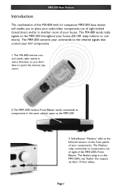
... point the remote anymore! 2.The MRF-200's built-in Front Blaster sends commands to components in the same cabinet space as the MRF-200. 3. The MX-800 sends radio signals to the MRF-200 throughout your house. The Flashers relay commands to the MRF-200's rear flasher line outputs via their 10 foot cables. Page 1 The MRF-200 converts your commands to place your audio/video components...
... point the remote anymore! 2.The MRF-200's built-in Front Blaster sends commands to components in the same cabinet space as the MRF-200. 3. The MX-800 sends radio signals to the MRF-200 throughout your house. The Flashers relay commands to the MRF-200's rear flasher line outputs via their 10 foot cables. Page 1 The MRF-200 converts your commands to place your audio/video components...
Owners Manual
Page 5
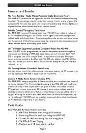
... of interference generated by installing an MRF-200 base station at any direction. Mounting Plate for wall mounting the mounting plate 1 - 9V-300mA Power Supply 6 - Page 2 Range depends on your home and the amount of sight audio/video components behind closed doors. Parts Guide The MRF-200 RF Base Station includes: 1 - If you select on the structure of the MRF-200 will not receive commands. Flashers with integrated antenna 1 - Each MRF200 is...
... of interference generated by installing an MRF-200 base station at any direction. Mounting Plate for wall mounting the mounting plate 1 - 9V-300mA Power Supply 6 - Page 2 Range depends on your home and the amount of sight audio/video components behind closed doors. Parts Guide The MRF-200 RF Base Station includes: 1 - If you select on the structure of the MRF-200 will not receive commands. Flashers with integrated antenna 1 - Each MRF200 is...
Owners Manual
Page 6
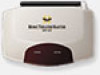
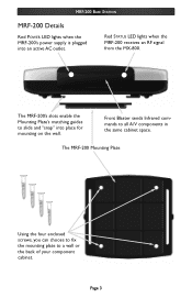
Front Blaster sends Infrared commands to a wall or the back of your component cabinet. The MRF-200 Mounting Plate Using the four enclosed screws, you can choose to fix the mounting plate to all A/V components in the same cabinet space. Page 3 The MRF-200's slots enable the Mounting Plate's matching guides to slide and "snap" into an active AC outlet. MRF-200 BASE STATION MRF-200 Details Red POWER LED lights when the MRF-200's power supply is plugged into place for mounting on the wall. Red STATUS LED lights when the MRF-200 receives an RF signal from the MX-800.
Front Blaster sends Infrared commands to a wall or the back of your component cabinet. The MRF-200 Mounting Plate Using the four enclosed screws, you can choose to fix the mounting plate to all A/V components in the same cabinet space. Page 3 The MRF-200's slots enable the Mounting Plate's matching guides to slide and "snap" into an active AC outlet. MRF-200 BASE STATION MRF-200 Details Red POWER LED lights when the MRF-200's power supply is plugged into place for mounting on the wall. Red STATUS LED lights when the MRF-200 receives an RF signal from the MX-800.
Owners Manual
Page 7
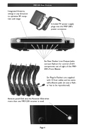
Integrated Antenna swings in case a flasher has to optimize RF reception and range. Bottom panel Dial sets the Receiver ID# when more than one MRF-200 receiver is used. Six Plug-In Flashers are supplied with 10 foot cables and six extra self-adhesive pads (in any direction to be repositioned). Six Rear Flasher Line Output Jacks connect flashers for control of A/V components out of sight of the MRF200's Front Blaster. MRF-200 BASE STATION Included 9V power supply plugs into the MRF-200's power connector. Page 4
Integrated Antenna swings in case a flasher has to optimize RF reception and range. Bottom panel Dial sets the Receiver ID# when more than one MRF-200 receiver is used. Six Plug-In Flashers are supplied with 10 foot cables and six extra self-adhesive pads (in any direction to be repositioned). Six Rear Flasher Line Output Jacks connect flashers for control of A/V components out of sight of the MRF200's Front Blaster. MRF-200 BASE STATION Included 9V power supply plugs into the MRF-200's power connector. Page 4
Owners Manual
Page 8
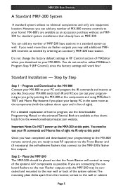
... will work fine! You need more than six flasher outputs you can add any number of MRF-200 base stations in the same room as possible. Since your MX-800 to the wall or cabinet Page 5 Standard Installation - Both are connecting the outboard flashers to program, use the downloadable Programming Manual or the animated Tutorial. If you have an MRF-200. Step by ordering an accessory MRF-200 base station. Once...
... will work fine! You need more than six flasher outputs you can add any number of MRF-200 base stations in the same room as possible. Since your MX-800 to the wall or cabinet Page 5 Standard Installation - Both are connecting the outboard flashers to program, use the downloadable Programming Manual or the animated Tutorial. If you have an MRF-200. Step by ordering an accessory MRF-200 base station. Once...
Owners Manual
Page 9
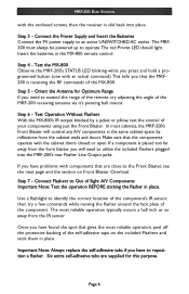
...: Always replace the self-adhesive tabs if you have to extend the range of the remote, try a few commands while moving the flasher around the face plate of Sight A/V Components Important Note: Test the operation BEFORE sticking the flasher in place. Test the MX-800 Observe the MRF-200's STATUS LED blinking while you press and hold a programmed button...
...: Always replace the self-adhesive tabs if you have to extend the range of the remote, try a few commands while moving the flasher around the face plate of Sight A/V Components Important Note: Test the operation BEFORE sticking the flasher in place. Test the MX-800 Observe the MRF-200's STATUS LED blinking while you press and hold a programmed button...
Owners Manual
Page 10
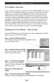
... limit the number of audio/video components can be necessary to turn off the Front Blaster Click on the following pages: Disabling the Front Blaster - Select OFF from the Program Menu. MRF-200 BASE STATION Front Blaster Overload A few models of components your MRF-200 can control to the MX-800. If you can purchase an additional MRF-200 (available as the first unit) then follow...
... limit the number of audio/video components can be necessary to turn off the Front Blaster Click on the following pages: Disabling the Front Blaster - Select OFF from the Program Menu. MRF-200 BASE STATION Front Blaster Overload A few models of components your MRF-200 can control to the MX-800. If you can purchase an additional MRF-200 (available as the first unit) then follow...
Owners Manual
Page 11
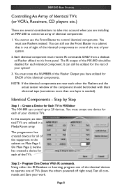
...note the NUMBER of the Flasher Output you are installing an MRF-200 to control an array of your system! 3. You must use Flashers instead. Identical Components - Create a Device for EACH of your identical TV's. In this example, six identical TV's are utilized in a cabinet that is needed). The ... and the actual sensor window of TV's (leave the others powered off right now).Test all of the MX-800 should be utilized for each of the identical components. Step 2 - MRF-200 BASE STATION Controlling An Array of Identical TV's (or VCR's, Receivers, CD players etc.) There are several...
...note the NUMBER of the Flasher Output you are installing an MRF-200 to control an array of your system! 3. You must use Flashers instead. Identical Components - Create a Device for EACH of your identical TV's. In this example, six identical TV's are utilized in a cabinet that is needed). The ... and the actual sensor window of TV's (leave the others powered off right now).Test all of the MX-800 should be utilized for each of the identical components. Step 2 - MRF-200 BASE STATION Controlling An Array of Identical TV's (or VCR's, Receivers, CD players etc.) There are several...
Owners Manual
Page 12
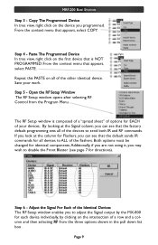
... the device you to ALL of the Identical Devices The RF Setup window enables you programmed. Open the RF Setup Window The RF Setup window opens after selecting RF Control from the three options shown in the pull down list box . Page 9 Step 5 - Step 6 - From the context menu that appears, select COPY. Adjust the Signal For Each of the flashers. MRF-200 BASE STATION Step 3 -
... the device you to ALL of the Identical Devices The RF Setup window enables you programmed. Open the RF Setup Window The RF Setup window opens after selecting RF Control from the three options shown in the pull down list box . Page 9 Step 5 - Step 6 - From the context menu that appears, select COPY. Adjust the Signal For Each of the flashers. MRF-200 BASE STATION Step 3 -
Owners Manual
Page 13
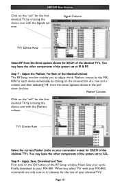
...Finally, download to IR & RF. Page 10 Signal Column TV1 Device Row Select RF from the seven options shown in the pull down list box. Step 7 - Next, Save your identical TV's! Likewise for the rest of the RF Setup window. Step 8 - MRF-200 BASE STATION Click on...connection notes) for the first identical TV, by crossing the device row with the Signals column. Apply, Save, Download and Test First click on the "cell" for EACH of the system set to it. TV1 Device Row Select the correct Flasher (refer to your MX-800. Flasher Column Click on the OK button of your work...
...Finally, download to IR & RF. Page 10 Signal Column TV1 Device Row Select RF from the seven options shown in the pull down list box. Step 7 - Next, Save your identical TV's! Likewise for the rest of the RF Setup window. Step 8 - MRF-200 BASE STATION Click on...connection notes) for the first identical TV, by crossing the device row with the Signals column. Apply, Save, Download and Test First click on the "cell" for EACH of the system set to it. TV1 Device Row Select the correct Flasher (refer to your MX-800. Flasher Column Click on the OK button of your work...
Owners Manual
Page 14
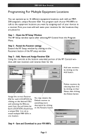
... down list. Step 2 - Save and Download to a receiver. MRF-200 BASE STATION Programming For Multiple Equipment Locations You can operate up to install multiple MRF-200's in : Step 1 - Step 3 - Step 4 - Assign the correct Receiver ID# for the Add new receivers by You may rename the clicking on the Add button. a unique ID#. descriptive by assigning each of the RF setup window. First, you want from the Program Menu. It...
... down list. Step 2 - Save and Download to a receiver. MRF-200 BASE STATION Programming For Multiple Equipment Locations You can operate up to install multiple MRF-200's in : Step 1 - Step 3 - Step 4 - Assign the correct Receiver ID# for the Add new receivers by You may rename the clicking on the Add button. a unique ID#. descriptive by assigning each of the RF setup window. First, you want from the Program Menu. It...
Owners Manual
Page 15
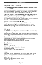
... The MRF-200 is too large to the MRF-200. Use an opaque material like electrical tape to the selected TV also responds. Specifications MRF-200 Power Supply: 9V 300mA IR Flasher Line Outputs: 2.5mm Mono Mini Jack RF Frequency: 418MHz Size: 5 1/8" x 3.5" x 1.25" (4.5" antenna up) MX-800 Range: 50 to the MRF-200? MRF-200 BASE STATION Frequently Asked Questions Can I use flasher/emitters that I have already installed in the system to connect to...
... The MRF-200 is too large to the MRF-200. Use an opaque material like electrical tape to the selected TV also responds. Specifications MRF-200 Power Supply: 9V 300mA IR Flasher Line Outputs: 2.5mm Mono Mini Jack RF Frequency: 418MHz Size: 5 1/8" x 3.5" x 1.25" (4.5" antenna up) MX-800 Range: 50 to the MRF-200? MRF-200 BASE STATION Frequently Asked Questions Can I use flasher/emitters that I have already installed in the system to connect to...

