
English Owners Manual
Page 1
UIP200 User's Manual Revision 1.0 © Uniden America Corp., May, 2004 This manual contains instructions for installing and operating your UIP200 SIP IP phone. If you have any questions about the information in this document, please call our Customer Service Department at 1-800-648-4921 or visit us on the web at http://bcs.uniden.com. It provides a description of the telephone's hardware, features, LCD displays, and explains setup, configuration, and basic operation.
UIP200 User's Manual Revision 1.0 © Uniden America Corp., May, 2004 This manual contains instructions for installing and operating your UIP200 SIP IP phone. If you have any questions about the information in this document, please call our Customer Service Department at 1-800-648-4921 or visit us on the web at http://bcs.uniden.com. It provides a description of the telephone's hardware, features, LCD displays, and explains setup, configuration, and basic operation.
English Owners Manual
Page 2
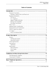
UIP200 User's Manual Page 2 of 27 Table of Contents Introduction ...5 Document Conventions...5 Warnings, Cautions, Notes, and Timesavers 5 Regulatory Information...6 FCC Part 15 ...6 U.L. Compliance ...6 Industry Canada (... Important Safety Considerations 7 Important Electrical Considerations 8 The FCC Wants You to Know 8 AC Adapter ...9 Power over Ethernet (PoE 9 Product Description 10 Features ...10 VoIP Specific Features 10 Operational Features...11 Control and Functions...11 Function Keys ...12 LED Status ...12 Specifications...12 Physical Interface ...13 Power Supply ...13 Speaker...
UIP200 User's Manual Page 2 of 27 Table of Contents Introduction ...5 Document Conventions...5 Warnings, Cautions, Notes, and Timesavers 5 Regulatory Information...6 FCC Part 15 ...6 U.L. Compliance ...6 Industry Canada (... Important Safety Considerations 7 Important Electrical Considerations 8 The FCC Wants You to Know 8 AC Adapter ...9 Power over Ethernet (PoE 9 Product Description 10 Features ...10 VoIP Specific Features 10 Operational Features...11 Control and Functions...11 Function Keys ...12 LED Status ...12 Specifications...12 Physical Interface ...13 Power Supply ...13 Speaker...
English Owners Manual
Page 3
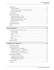
UIP200 User's Manual Page 3 of 27 Making Calls...16 Using the Handset ...16 Using the Speakerphone or a Headset (Hands-free 16 Using On-Hook Dialing 17 Receiving Calls ......-Menu ...23 Programming a 1-Touch Number 23 Clearing or Editing the 1-Touch Number 24 Programming the 2 Touch Number 24 Clearing or Editing the 2-Touch Number 25 Phone Settings Sub-Menu 25 Changing the LCD Contrast 25 Changing the Display Language 25 Adjusting the Date and Time 26 Network Setting ...27 View Info...
UIP200 User's Manual Page 3 of 27 Making Calls...16 Using the Handset ...16 Using the Speakerphone or a Headset (Hands-free 16 Using On-Hook Dialing 17 Receiving Calls ......-Menu ...23 Programming a 1-Touch Number 23 Clearing or Editing the 1-Touch Number 24 Programming the 2 Touch Number 24 Clearing or Editing the 2-Touch Number 25 Phone Settings Sub-Menu 25 Changing the LCD Contrast 25 Changing the Display Language 25 Adjusting the Date and Time 26 Network Setting ...27 View Info...

English Owners Manual
Page 4
UIP200 User's Manual Page 4 of 27 Figures in This Document Figure 1 Attaching the Wall Mount Bracket 14 Figure 2 Mount the Phone on the Wall Plate 14 Figure 3 LCD in standby mode 16 Figure 4 LCD when a Call is Connected 16 Figure 5 LCD display when Receiving a Call 17 Tables in This Document Table 1 Revision History ...6 Table 2 Control Keys and Their Functions 11 Table 3 LEDs and Their Meanings 12 Table 4 Fixed-Function Key and Programmable Key Defaults 20 Table 5 Configuration Menus and Their Functions 23 Rev. 1.0, © UAC, May, 2004
UIP200 User's Manual Page 4 of 27 Figures in This Document Figure 1 Attaching the Wall Mount Bracket 14 Figure 2 Mount the Phone on the Wall Plate 14 Figure 3 LCD in standby mode 16 Figure 4 LCD when a Call is Connected 16 Figure 5 LCD display when Receiving a Call 17 Tables in This Document Table 1 Revision History ...6 Table 2 Control Keys and Their Functions 11 Table 3 LEDs and Their Meanings 12 Table 4 Fixed-Function Key and Programmable Key Defaults 20 Table 5 Configuration Menus and Their Functions 23 Rev. 1.0, © UAC, May, 2004
English Owners Manual
Page 5
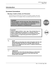
...government regulation or company policy. ! CAUTION Cautions appear with the stop sign. Rev. 1.0, © UAC, May, 2004 UIP200 User's Manual Page 5 of these conventions and how they are hints that have worked well in the field. Most notes are required by suggestions from.... ! Below is no danger. Most timesavers are not followed correctly. NOTE Notes point out important and useful information that the user should remember, but there is an example of 27 Introduction Document Conventions Warnings, Cautions, Notes, and Timesavers This document uses particular...
...government regulation or company policy. ! CAUTION Cautions appear with the stop sign. Rev. 1.0, © UAC, May, 2004 UIP200 User's Manual Page 5 of these conventions and how they are hints that have worked well in the field. Most notes are required by suggestions from.... ! Below is no danger. Most timesavers are not followed correctly. NOTE Notes point out important and useful information that the user should remember, but there is an example of 27 Introduction Document Conventions Warnings, Cautions, Notes, and Timesavers This document uses particular...
English Owners Manual
Page 6
... conversation. Table 1 Revision History Revision Publication Date 1.0 May 31, 2004 Changes First release of FCC Rules. UIP200 User's Manual Page 6 of 27 Regulatory Information FCC Part 15 This product complies with the limits for this document. Users should not attempt to make such connections themselves, but should contact the appropriate electric inspection authority, or...
... conversation. Table 1 Revision History Revision Publication Date 1.0 May 31, 2004 Changes First release of FCC Rules. UIP200 User's Manual Page 6 of 27 Regulatory Information FCC Part 15 This product complies with the limits for this document. Users should not attempt to make such connections themselves, but should contact the appropriate electric inspection authority, or...
English Owners Manual
Page 7
... cord. When the power supply cord is required. for example, near a sink or in a wet area. # Do not place this product on the marking label. UIP200 User's Manual Page 7 of 27 Important Safety Considerations When using this product, basic safety precautions should always be followed to reduce the risk of fire, electrical shock...
... cord. When the power supply cord is required. for example, near a sink or in a wet area. # Do not place this product on the marking label. UIP200 User's Manual Page 7 of 27 Important Safety Considerations When using this product, basic safety precautions should always be followed to reduce the risk of fire, electrical shock...

English Owners Manual
Page 8
If the product exhibits a distinct change in performance. # Uniden works to it. This product is approaching. Important Electrical Considerations Unplug all electrical appliances when you know an electrical storm is no guarantee... can radiate radio frequency energy and, if not installed and used in accordance with the limits for compliance could void the user's authority to operate the equipment. Wash hands after handling. UIP200 User's Manual Page 8 of other reproductive harm. This equipment generates, uses and can result in a particular installation. WARNING The cords ...
If the product exhibits a distinct change in performance. # Uniden works to it. This product is approaching. Important Electrical Considerations Unplug all electrical appliances when you know an electrical storm is no guarantee... can radiate radio frequency energy and, if not installed and used in accordance with the limits for compliance could void the user's authority to operate the equipment. Wash hands after handling. UIP200 User's Manual Page 8 of other reproductive harm. This equipment generates, uses and can result in a particular installation. WARNING The cords ...

English Owners Manual
Page 9
...that is intended to be supplied by IPAD-532 a UL Listed direct plug-in power unit marked "Class 2" or "LPS" or "I.T.E. AC Adapter The UIP200 is not controlled by a switch.) Place the power cord where it will not create a trip hazard, or where it could become chafed or frayed, ... electrical shock. the input is used. Rev. 1.0, © UAC, May, 2004 Power over Ethernet (PoE) The UIP200 may obtain power via the LAN when a Power over Ethernet switch is -48 VDC, 6.4 W. UIP200 User's Manual Page 9 of 27 encouraged to try to correct the interference by one that to which the receiver is...
...that is intended to be supplied by IPAD-532 a UL Listed direct plug-in power unit marked "Class 2" or "LPS" or "I.T.E. AC Adapter The UIP200 is not controlled by a switch.) Place the power cord where it will not create a trip hazard, or where it could become chafed or frayed, ... electrical shock. the input is used. Rev. 1.0, © UAC, May, 2004 Power over Ethernet (PoE) The UIP200 may obtain power via the LAN when a Power over Ethernet switch is -48 VDC, 6.4 W. UIP200 User's Manual Page 9 of 27 encouraged to try to correct the interference by one that to which the receiver is...

English Owners Manual
Page 10
UIP200 User's Manual Page 10 of 27 Product Description Features # 11 LED indicators (8 programmable keys, Headset/speaker, Hold, and Receive Signaling Lamp) # 12-key dial pad # 16 specific ... time display # Call duration display # On-hook dialing # LCD contrast control # Display Caller ID (Name & Number) # Hands free talking via speakerphone VoIP Specific Features The following features are specific to the VoIP function. # SIP standard compliant (RFC 3261) # Voice Codec: G.711 (µ-Law and A-Law), G729A # Acoustic Echo Cancellation (AEC) (G.165) # DHCP...
UIP200 User's Manual Page 10 of 27 Product Description Features # 11 LED indicators (8 programmable keys, Headset/speaker, Hold, and Receive Signaling Lamp) # 12-key dial pad # 16 specific ... time display # Call duration display # On-hook dialing # LCD contrast control # Display Caller ID (Name & Number) # Hands free talking via speakerphone VoIP Specific Features The following features are specific to the VoIP function. # SIP standard compliant (RFC 3261) # Voice Codec: G.711 (µ-Law and A-Law), G729A # Acoustic Echo Cancellation (AEC) (G.165) # DHCP...
English Owners Manual
Page 11
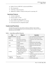
... off Places the remote party on the line Call waiting tone sounds Standby Entering numbers Standby Within a sub-menu Manual configuration When a phone number has dialed but not connected When entering character strings or digits Setup menus UP ▲ and DOWN ▼... configuration # Firmware update via TFTP # Auto Configuration update using TFTP # Remote Reboot using NOTIFY event message # Password protection for connecting a PC. UIP200 User's Manual Page 11 of 27 # Quality of Service (IEEE 802.1 p/q based and DiffServ) # Jitter compensation # 10/100 Base-T Ethernet Interface # Additional...
... off Places the remote party on the line Call waiting tone sounds Standby Entering numbers Standby Within a sub-menu Manual configuration When a phone number has dialed but not connected When entering character strings or digits Setup menus UP ▲ and DOWN ▼... configuration # Firmware update via TFTP # Auto Configuration update using TFTP # Remote Reboot using NOTIFY event message # Password protection for connecting a PC. UIP200 User's Manual Page 11 of 27 # Quality of Service (IEEE 802.1 p/q based and DiffServ) # Jitter compensation # 10/100 Base-T Ethernet Interface # Additional...
English Owners Manual
Page 12
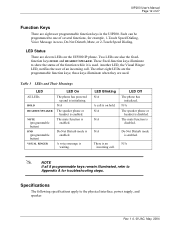
.... 1.0, © UAC, May, 2004 LED Status There are the programmable function keys; There is an N/A incoming call is on the UIP200 IP phone. A voice message is enabled. The mute function is enabled. UIP200 User's Manual Page 12 of the function while it is used . LED Blinking N/A A call . ! Each can be programmed to show the status...
.... 1.0, © UAC, May, 2004 LED Status There are the programmable function keys; There is an N/A incoming call is on the UIP200 IP phone. A voice message is enabled. The mute function is enabled. UIP200 User's Manual Page 12 of the function while it is used . LED Blinking N/A A call . ! Each can be programmed to show the status...

English Owners Manual
Page 13
UIP200 User's Manual Page 13 of 27 Physical Interface # PC connection 10/100 Base-T (RJ-45) # LAN connection 10/100 Base-T (RJ-45) # Handset connection (RJ-22) x 1 # Headset (Phone Jack φ2.5mm) X 1 # DC Jack (EIAJ Class2, Center +) X 1 Power Supply # Input to the phone from the power supply: 5 Vdc, 1.7 A (IPAD-532) # Input to the phone from Power Over Ethernet: nominal -48 Vdc (-36 to -57) Speaker # 8 Ω 8W φ57mm Rev. 1.0, © UAC, May, 2004
UIP200 User's Manual Page 13 of 27 Physical Interface # PC connection 10/100 Base-T (RJ-45) # LAN connection 10/100 Base-T (RJ-45) # Handset connection (RJ-22) x 1 # Headset (Phone Jack φ2.5mm) X 1 # DC Jack (EIAJ Class2, Center +) X 1 Power Supply # Input to the phone from the power supply: 5 Vdc, 1.7 A (IPAD-532) # Input to the phone from Power Over Ethernet: nominal -48 Vdc (-36 to -57) Speaker # 8 Ω 8W φ57mm Rev. 1.0, © UAC, May, 2004
English Owners Manual
Page 14
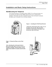
... of the bracket is at the top. UIP200 User's Manual Page 14 of 27 Installation and Basic Setup Instructions Wall-Mounting the Telephone The wall mount bracket is at the bottom of the phone and the narrow end is included with the UIP200. Figure 2 Mount the Phone on the plate. The wall mount bracket... can only be mounted over the screws of the UIP200, allowing the user to wall mount the telephone. The bracket can be attached to the rear of the phone. Figure 1 Attaching the Wall Mount Bracket Attach the wall mount bracket to the bottom of a ...
... of the bracket is at the top. UIP200 User's Manual Page 14 of 27 Installation and Basic Setup Instructions Wall-Mounting the Telephone The wall mount bracket is at the bottom of the phone and the narrow end is included with the UIP200. Figure 2 Mount the Phone on the plate. The wall mount bracket... can only be mounted over the screws of the UIP200, allowing the user to wall mount the telephone. The bracket can be attached to the rear of the phone. Figure 1 Attaching the Wall Mount Bracket Attach the wall mount bracket to the bottom of a ...
English Owners Manual
Page 15
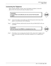
...network to the port labeled LAN on the left side of the phone as viewed from the LAN, connect the AC adapter to the power jack located on the back of the phone and plug it in to a standard phone line. UIP200 User's Manual Page 15 of 27 Connecting the Telephone Before using Power over Ethernet..., do not connect the AC power supply. Step 3: If the phone is not receiving power from the front of the...
...network to the port labeled LAN on the left side of the phone as viewed from the LAN, connect the AC adapter to the power jack located on the back of the phone and plug it in to a standard phone line. UIP200 User's Manual Page 15 of 27 Connecting the Telephone Before using Power over Ethernet..., do not connect the AC power supply. Step 3: If the phone is not receiving power from the front of the...
English Owners Manual
Page 16
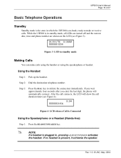
...phone will show the call connects, the LCD will automatically connect. Rev. 1.0, © UAC, May, 2004 After the call duration timer (see Figure 3). 01/01/70 9:00AM 5555551234 Figure 3 LCD in standby mode Making Calls You can make or receive calls. Using the Handset Step 1: Pick up the handset. UIP200 User's Manual... Page 16 of 27 Basic Telephone Operations Standby Standby mode is the state in which the UIP200 is on the LCD (see Figure 4). 0:04 5555553154 Figure 4 LCD when ...
...phone will show the call connects, the LCD will automatically connect. Rev. 1.0, © UAC, May, 2004 After the call duration timer (see Figure 3). 01/01/70 9:00AM 5555551234 Figure 3 LCD in standby mode Making Calls You can make or receive calls. Using the Handset Step 1: Pick up the handset. UIP200 User's Manual... Page 16 of 27 Basic Telephone Operations Standby Standby mode is the state in which the UIP200 is on the LCD (see Figure 4). 0:04 5555553154 Figure 4 LCD when ...
English Owners Manual
Page 17
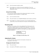
...Step 3: Press the DIAL key to initiate the connection immediately. If you wait approximately four seconds after you enter the last digit enter, the phone will automatically connect. Step 1: Enter the destination number. Step 3: Press the DIAL key to initiate the connection; JOHN DOE 8175553198 Figure 5 LCD...the headset, the speakerphone, and the ringer. if you wait approximately four seconds after you enter the last digit enter, the phone will automatically connect. UIP200 User's Manual Page 17 of the calling party. Step 2: Press ▲ (UP) or ▼ (DOWN) to make the...
...Step 3: Press the DIAL key to initiate the connection immediately. If you wait approximately four seconds after you enter the last digit enter, the phone will automatically connect. Step 1: Enter the destination number. Step 3: Press the DIAL key to initiate the connection; JOHN DOE 8175553198 Figure 5 LCD...the headset, the speakerphone, and the ringer. if you wait approximately four seconds after you enter the last digit enter, the phone will automatically connect. UIP200 User's Manual Page 17 of the calling party. Step 2: Press ▲ (UP) or ▼ (DOWN) to make the...
English Owners Manual
Page 18
... the volume level you want, wait for 2.5 seconds. Changing the Ringer Volume Step 1: Be certain that the phone is in standby (i.e., the handset is in the headset. Step 4: The new volume setting is not pressed). ...▲ (UP) or ▼ (DOWN) to adjust the volume. Step 5: The new volume setting is plugged into the phone, unplug the headset. Step 2: Press ▲ (UP) or ▼ (DOWN) to adjust the volume. Step 3: Press ... May, 2004 Step 4: The new volume setting is saved. UIP200 User's Manual Page 18 of 27 Step 3: When you reach the volume level you want, wait for 2.5 seconds.
... the volume level you want, wait for 2.5 seconds. Changing the Ringer Volume Step 1: Be certain that the phone is in standby (i.e., the handset is in the headset. Step 4: The new volume setting is not pressed). ...▲ (UP) or ▼ (DOWN) to adjust the volume. Step 5: The new volume setting is plugged into the phone, unplug the headset. Step 2: Press ▲ (UP) or ▼ (DOWN) to adjust the volume. Step 3: Press ... May, 2004 Step 4: The new volume setting is saved. UIP200 User's Manual Page 18 of 27 Step 3: When you reach the volume level you want, wait for 2.5 seconds.

English Owners Manual
Page 19
UIP200 User's Manual Page 19 of 27 Transferring a Call The steps below represent the most common method of your network... the caller has been holding for the other party before hanging up the phone and transferring the call to let you do not want to answer (a blind transfer), hang up the phone. Hold During a conversation, you are on hold , and you disconnect one.../FLASH key. ! After 360 seconds (six minutes), an alert tone will display the duration timer and phone number of the party on the line. Call Waiting Operation Step 1: If the call-waiting feature is another call .
UIP200 User's Manual Page 19 of 27 Transferring a Call The steps below represent the most common method of your network... the caller has been holding for the other party before hanging up the phone and transferring the call to let you do not want to answer (a blind transfer), hang up the phone. Hold During a conversation, you are on hold , and you disconnect one.../FLASH key. ! After 360 seconds (six minutes), an alert tone will display the duration timer and phone number of the party on the line. Call Waiting Operation Step 1: If the call-waiting feature is another call .
English Owners Manual
Page 20
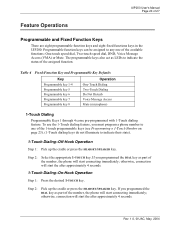
... Pick up the cradle or press the HEADSET/SPEAKER key. The programmable keys also act as LEDs to one of the number, the phone will start connecting immediately; otherwise, connection will start the after approximately 4 seconds. 1-Touch Dialing-On-Hook Operation Step 1: Press the desired... and Fixed Function Keys There are eight programmable function keys and eight fixed functions keys in the UIP200. UIP200 User's Manual Page 20 of the number, the phone will start connecting immediately; Step 2: Select the appropriate 1-TOUCH key. Rev. 1.0, © UAC, May, 2004
... Pick up the cradle or press the HEADSET/SPEAKER key. The programmable keys also act as LEDs to one of the number, the phone will start connecting immediately; otherwise, connection will start the after approximately 4 seconds. 1-Touch Dialing-On-Hook Operation Step 1: Press the desired... and Fixed Function Keys There are eight programmable function keys and eight fixed functions keys in the UIP200. UIP200 User's Manual Page 20 of the number, the phone will start connecting immediately; Step 2: Select the appropriate 1-TOUCH key. Rev. 1.0, © UAC, May, 2004


