
User Manual
Page 6
... Load Fail-Safe Defaults 3-30 Load Optimized Defaults 3-31 Set Supervisor/User Password 3-32 Save & Exit Setup 3-34 Exit Without Saving 3-35 vi Installation 2-1 CPU 2-2 Memory Installation 2-4 Power Supply 2-6 Back Panel 2-7 Connectors 2-9 Jumpers 2-14 Slots 2-18 PCI Interrupt Request Routing 2-19 3. Specifications 1-1 Specifications 1-2 Layout 1-4 Connectors Guide 1-5 2. Contents...
... Load Fail-Safe Defaults 3-30 Load Optimized Defaults 3-31 Set Supervisor/User Password 3-32 Save & Exit Setup 3-34 Exit Without Saving 3-35 vi Installation 2-1 CPU 2-2 Memory Installation 2-4 Power Supply 2-6 Back Panel 2-7 Connectors 2-9 Jumpers 2-14 Slots 2-18 PCI Interrupt Request Routing 2-19 3. Specifications 1-1 Specifications 1-2 Layout 1-4 Connectors Guide 1-5 2. Contents...

User Manual
Page 9
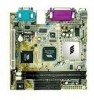
...• Internal L1 128KB and L2 64KB cache memory Chipset • VIA 8601A North Bridge • VT8231 South Bridge Graphics • Integrated Trident Blade 3D graphics core Audio • VT1612A AC'97 Codec • 3 Audio jacks: Line-in, Line-out and Mic-in Main Memory • 2 x PC100/133 DIMM slots. ...PCI Bus IDE • Supports up to 4 IDE devices • Ultra DMA 33/66/100 LAN • VIA VT6103 Ethernet PHY • Supports Ethernet 10/100Mb USB • 2 USB ports •...
...• Internal L1 128KB and L2 64KB cache memory Chipset • VIA 8601A North Bridge • VT8231 South Bridge Graphics • Integrated Trident Blade 3D graphics core Audio • VT1612A AC'97 Codec • 3 Audio jacks: Line-in, Line-out and Mic-in Main Memory • 2 x PC100/133 DIMM slots. ...PCI Bus IDE • Supports up to 4 IDE devices • Ultra DMA 33/66/100 LAN • VIA VT6103 Ethernet PHY • Supports Ethernet 10/100Mb USB • 2 USB ports •...

User Manual
Page 13
..., be damaged if installed incorrectly. If possible, use a grounded wrist strap before handling computer components. This chapter contains the following topics: Central Processing Unit (CPU) 2-2 Memory Installation 2-4 Power Supply 2-6 Back Panel 2-7 Connectors 2-9 Jumpers 2-14 Slots 2-18 PCI Interrupt Request Routing 2-19 2-1 Some components can be damaged by static electricity. Hardware Setup...
..., be damaged if installed incorrectly. If possible, use a grounded wrist strap before handling computer components. This chapter contains the following topics: Central Processing Unit (CPU) 2-2 Memory Installation 2-4 Power Supply 2-6 Back Panel 2-7 Connectors 2-9 Jumpers 2-14 Slots 2-18 PCI Interrupt Request Routing 2-19 2-1 Some components can be damaged by static electricity. Hardware Setup...

User Manual
Page 16
... so that the white retaining latches rotate up and secure the module in place (see picture below). 2-4 Chapter 2 Memory Installation The VIA EPIA Mini-ITX Mainboard provides two 168-pin DIMM slots for PC 100/133 SDRAM memory modules. DIMM 1 & DIMM 2 SDRAM Module Installation Procedures 1.) Push the white retaining latches at least one module must be...
... so that the white retaining latches rotate up and secure the module in place (see picture below). 2-4 Chapter 2 Memory Installation The VIA EPIA Mini-ITX Mainboard provides two 168-pin DIMM slots for PC 100/133 SDRAM memory modules. DIMM 1 & DIMM 2 SDRAM Module Installation Procedures 1.) Push the white retaining latches at least one module must be...

User Manual
Page 17
Hardware Setup Available SDRAM Configurations Refer to the table below for available SDRAM configurations on the VIA EPIA Mini-ITX Mainboard. Socket Memory Module Total Mem ory DIMM 1 DIMM 2 32MB, 64MB, 128MB, 32MB~512MB 256MB, 512MB 32MB, 64MB, 128MB, 32MB~512MB 256MB, 512MB Maximum System Memory Supported 1GB 2-5
Hardware Setup Available SDRAM Configurations Refer to the table below for available SDRAM configurations on the VIA EPIA Mini-ITX Mainboard. Socket Memory Module Total Mem ory DIMM 1 DIMM 2 32MB, 64MB, 128MB, 32MB~512MB 256MB, 512MB 32MB, 64MB, 128MB, 32MB~512MB 256MB, 512MB Maximum System Memory Supported 1GB 2-5

User Manual
Page 26
... configuration, use the JBAT1 (Clear CMOS Jumper ) to clear the CMOS memory of system parameter settings. If you to clear data. it may cause damage to clear the data: 1 3 1 1 3 3 Normal Clear CMOS 1-2: Normal 2-3: Clear CMOS WARNING! Chapter 2 Jumpers The VIA EPIA Mini-ITX Mainboard provides a series of all the mainboard settings. Follow the instructions below...
... configuration, use the JBAT1 (Clear CMOS Jumper ) to clear the CMOS memory of system parameter settings. If you to clear data. it may cause damage to clear the data: 1 3 1 1 3 3 Normal Clear CMOS 1-2: Normal 2-3: Clear CMOS WARNING! Chapter 2 Jumpers The VIA EPIA Mini-ITX Mainboard provides a series of all the mainboard settings. Follow the instructions below...

User Manual
Page 42
... Dot Crawl Type Set the TV Dot Crawl Type. Settings: Disabled and Enabled. Settings: NTSC and PAL. Settings: DeDot and Dot. 3-11 Memory Hole Select whether to have a memory hole at 15M to 16M area. Note: Change these settings only if you are familiar with the chipset. Settings: Disabled and Enabled. Settings...
... Dot Crawl Type Set the TV Dot Crawl Type. Settings: Disabled and Enabled. Settings: NTSC and PAL. Settings: DeDot and Dot. 3-11 Memory Hole Select whether to have a memory hole at 15M to 16M area. Note: Change these settings only if you are familiar with the chipset. Settings: Disabled and Enabled. Settings...

User Manual
Page 51
.... S1/Power On Suspend (POS) is lost and hardware maintains all system context. In this state, power is supplied only to main memory, and context is restored from the memory when a "wakeup" event occurs. S3/STR - S3/Suspend To RAM (STR) is controled by APM. Settings are: S1/POS - The ...system context is saved to essential components such as main memory and wakeup-capable devices. Settings: No and Yes. 3-20 If your own style of computer use. Windows 98/98SE/ME/2000/XP) select Enabled. PM...
.... S1/Power On Suspend (POS) is lost and hardware maintains all system context. In this state, power is supplied only to main memory, and context is restored from the memory when a "wakeup" event occurs. S3/STR - S3/Suspend To RAM (STR) is controled by APM. Settings are: S1/POS - The ...system context is saved to essential components such as main memory and wakeup-capable devices. Settings: No and Yes. 3-20 If your own style of computer use. Windows 98/98SE/ME/2000/XP) select Enabled. PM...

User Manual
Page 58
... is set to set each IRQ a type depending on the type of device using the IRQ. Press and you will automatically assign IRQ, DMA and memory base address fields. BIOS Setup Resource Controlled By The BIOS can automatically configure all the boot and Plug and Play compatible devices. The settings: Auto...
... is set to set each IRQ a type depending on the type of device using the IRQ. Press and you will automatically assign IRQ, DMA and memory base address fields. BIOS Setup Resource Controlled By The BIOS can automatically configure all the boot and Plug and Play compatible devices. The settings: Auto...

User Manual
Page 63
... BIOS to request a password each time the system is the Security Option of the Advanced BIOS Features menu. This prevents an unauthorized person from CMOS memory. If the Security Option is set password from changing any password. Re-type the password and press . A message will show up to eight characters in...
... BIOS to request a password each time the system is the Security Option of the Advanced BIOS Features menu. This prevents an unauthorized person from CMOS memory. If the Security Option is set password from changing any password. Re-type the password and press . A message will show up to eight characters in...