User Manual
Page 6
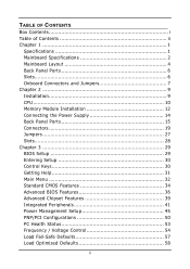
TABLE OF CONTENTS Box Contents i Table of Contents ii Chapter 1 1 Specifications 1 Mainboard Specifications 2 Mainboard Layout 4 Back Panel Ports 6 Slots 6 Onboard Connectors and Jumpers 7 Chapter 2 9 Installation 9 CPU 10 Memory Module Installation 12 Connecting the Power Supply 14 Back Panel Ports ...
TABLE OF CONTENTS Box Contents i Table of Contents ii Chapter 1 1 Specifications 1 Mainboard Specifications 2 Mainboard Layout 4 Back Panel Ports 6 Slots 6 Onboard Connectors and Jumpers 7 Chapter 2 9 Installation 9 CPU 10 Memory Module Installation 12 Connecting the Power Supply 14 Back Panel Ports ...
User Manual
Page 9
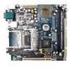
... 66% of the size of the company's open industry-wide total connectivity initiative. CHAPTER 1 Specifications The ultra-compact and highly integrated VIA EPIA-MII Mini-ITX Mainboard is the smallest form factor mainboard specification available today, developed by VIA Technologies, Inc. The mainboard comes with an embedded VIA Processor, boasting ultra low power consumption and cool, quiet operation. 1
... 66% of the size of the company's open industry-wide total connectivity initiative. CHAPTER 1 Specifications The ultra-compact and highly integrated VIA EPIA-MII Mini-ITX Mainboard is the smallest form factor mainboard specification available today, developed by VIA Technologies, Inc. The mainboard comes with an embedded VIA Processor, boasting ultra low power consumption and cool, quiet operation. 1
User Manual
Page 17
It is recommended to use a grounded wrist strap before handling computer components. Static electricity can damage some components. 9 Some components may be damaged if they are installed incorrectly. CHAPTER 2 Installation This chapter provides you with information about hardware setup procedures. While installing the mainboard, carefully hold the components and closely follow the installation procedures.
It is recommended to use a grounded wrist strap before handling computer components. Static electricity can damage some components. 9 Some components may be damaged if they are installed incorrectly. CHAPTER 2 Installation This chapter provides you with information about hardware setup procedures. While installing the mainboard, carefully hold the components and closely follow the installation procedures.
User Manual
Page 18
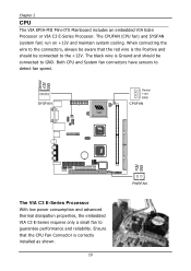
... performance and reliability. Ensure that the red wire is correctly installed as shown. 10 PWRFAN Chapter 2 CPU The VIA EPIA-MII Mini-ITX Mainboard includes an embedded VIA Eden Processor or VIA C3 E-Series Processor. SYSFAN Sensor +12V GND CPUFAN CLE266 The VIA C3 E-Series Processor With low power consumption and advanced thermal dissipation properties, the embedded...
... performance and reliability. Ensure that the red wire is correctly installed as shown. 10 PWRFAN Chapter 2 CPU The VIA EPIA-MII Mini-ITX Mainboard includes an embedded VIA Eden Processor or VIA C3 E-Series Processor. SYSFAN Sensor +12V GND CPUFAN CLE266 The VIA C3 E-Series Processor With low power consumption and advanced thermal dissipation properties, the embedded...
User Manual
Page 20
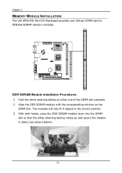
Align the DDR SDRAM module with the corresponding notches on the DIMM slot. With both hands, press the DDR SDRAM module down into the DIMM slot so that the white retaining latches rotate up and secure the module in the correct position. 3. CLE266 DDR SDRAM Module Installation Procedures 1. Push the white retaining latches at either end of the DIMM slot outwards. 2. The modules will only fit if placed in place (see picture below). 12 Chapter 2 MEMORY MODULE INSTALLATION The VIA EPIA-MII Mini-ITX Mainboard provides one 184-pin DIMM slot for DDR266 SDRAM memory modules.
Align the DDR SDRAM module with the corresponding notches on the DIMM slot. With both hands, press the DDR SDRAM module down into the DIMM slot so that the white retaining latches rotate up and secure the module in the correct position. 3. CLE266 DDR SDRAM Module Installation Procedures 1. Push the white retaining latches at either end of the DIMM slot outwards. 2. The modules will only fit if placed in place (see picture below). 12 Chapter 2 MEMORY MODULE INSTALLATION The VIA EPIA-MII Mini-ITX Mainboard provides one 184-pin DIMM slot for DDR266 SDRAM memory modules.

User Manual
Page 21
Installation Available DDR SDRAM Configurations Refer to the table below for available DDR SDRAM configurations on the mainboard. Slot DIMM (Bank 0 & 1) Module Size 64MB, 128MB, 256MB, 512MB, 1GB Maximum System Memory Supported Total Memory 64MB - 1GB 64MB - 1GB 13
Installation Available DDR SDRAM Configurations Refer to the table below for available DDR SDRAM configurations on the mainboard. Slot DIMM (Bank 0 & 1) Module Size 64MB, 128MB, 256MB, 512MB, 1GB Maximum System Memory Supported Total Memory 64MB - 1GB 64MB - 1GB 13
User Manual
Page 22
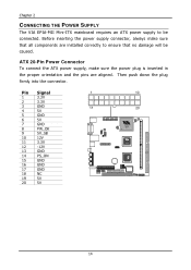
... NC 19 5V 20 5V 1 10 11 20 CLE266 14 Then push down the plug firmly into the connector. Chapter 2 CONNECTING THE POWER SUPPLY The VIA EPIA-MII Mini-ITX mainboard requires an ATX power supply to ensure that all components are aligned.
... NC 19 5V 20 5V 1 10 11 20 CLE266 14 Then push down the plug firmly into the connector. Chapter 2 CONNECTING THE POWER SUPPLY The VIA EPIA-MII Mini-ITX mainboard requires an ATX power supply to ensure that all components are aligned.
User Manual
Page 23
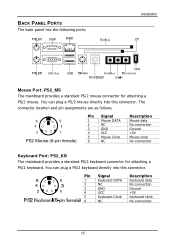
...) Pin Signal 1 Mouse DATA 2 NC 3 GND 4 VCC 5 Mouse Clock 6 NC Description Mouse data No connection Ground +5V Mouse clock No connection Keyboard Port: PS2_KB The mainboard provides a standard PS/2 keyboard connector for attaching a PS/2 mouse. BACK PANEL PORTS The back panel has the following ports: Installation Mouse Port: PS2_MS The...
...) Pin Signal 1 Mouse DATA 2 NC 3 GND 4 VCC 5 Mouse Clock 6 NC Description Mouse data No connection Ground +5V Mouse clock No connection Keyboard Port: PS2_KB The mainboard provides a standard PS/2 keyboard connector for attaching a PS/2 mouse. BACK PANEL PORTS The back panel has the following ports: Installation Mouse Port: PS2_MS The...
User Manual
Page 24
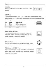
USB Ports The mainboard provides 2 USB 2.0/1.1 ports (plus 1 pin-header for more details. 16 You can be used either as a RCA Video port or as an S/PDIF port. See ... NTSC and PAL modes. Pin Signal 1 VCC 2 -DATA 3 +DATA 4 GND Description +5V Negative data channel Positive data channel Ground RJ45 10/100 NIC Port The mainboard provides one standard RJ-45 port for connection to the LAN port. S-Video Port This port allows S-Video output in the Jumpers section for up...
USB Ports The mainboard provides 2 USB 2.0/1.1 ports (plus 1 pin-header for more details. 16 You can be used either as a RCA Video port or as an S/PDIF port. See ... NTSC and PAL modes. Pin Signal 1 VCC 2 -DATA 3 +DATA 4 GND Description +5V Negative data channel Positive data channel Ground RJ45 10/100 NIC Port The mainboard provides one standard RJ-45 port for connection to the LAN port. S-Video Port This port allows S-Video output in the Jumpers section for up...

User Manual
Page 25
...Serial Out or Transmit Data Data Terminal Ready Ground Data Set Ready Request To Send Clear To Send Ring Indicate Card Slots: PCMCIA, CF The mainboard comes with an add-on the same side as the ports. 17 You can attach a serial mouse or other serial devices directly to this... port. These slots are accessed on card that provides support for PCMCIA and CF cards. IEEE 1394 Port The mainboard provides one 9-pin male Serial Port connector COM1. Installation Serial Ports: COM1 The mainboard offers one standard 1394 port. The CF slot supports both type I and type II.
...Serial Out or Transmit Data Data Terminal Ready Ground Data Set Ready Request To Send Clear To Send Ring Indicate Card Slots: PCMCIA, CF The mainboard comes with an add-on the same side as the ports. 17 You can attach a serial mouse or other serial devices directly to this... port. These slots are accessed on card that provides support for PCMCIA and CF cards. IEEE 1394 Port The mainboard provides one 9-pin male Serial Port connector COM1. Installation Serial Ports: COM1 The mainboard offers one standard 1394 port. The CF slot supports both type I and type II.
User Manual
Page 27
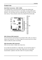
... drive to the hard disk documentation supplied by setting the jumper accordingly. Please refer to slave mode. CONNECTORS Installation Hard Disk Connectors: IDE1 & IDE2 The mainboard has a 32-bit Enhanced PCI IDE and Ultra DMA 66/100 controller that provides PIO mode 0~4, Bus Master, and Ultra DMA 66/100 functions. IDE1...
... drive to the hard disk documentation supplied by setting the jumper accordingly. Please refer to slave mode. CONNECTORS Installation Hard Disk Connectors: IDE1 & IDE2 The mainboard has a 32-bit Enhanced PCI IDE and Ultra DMA 66/100 controller that provides PIO mode 0~4, Bus Master, and Ultra DMA 66/100 functions. IDE1...
User Manual
Page 30
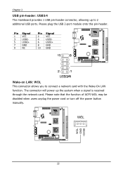
.... WOL GND +5VSB 22 The connector will power up to connect a network card with the Wake-On LAN function. Chapter 2 USB pin-header: USB3/4 The mainboard provides 1 USB pin-header connector, allowing up the system when a signal is received through the network card. Please plug the USB 2-port module onto this...
.... WOL GND +5VSB 22 The connector will power up to connect a network card with the Wake-On LAN function. Chapter 2 USB pin-header: USB3/4 The mainboard provides 1 USB pin-header connector, allowing up the system when a signal is received through the network card. Please plug the USB 2-port module onto this...

User Manual
Page 32
Chapter 2 CD Audio Connector: CD_IN This connector is for use on the front panel. Only the line-out and microphone functions are available for the CD-ROM audio connector. To connect the front audio cable, first remove the two red plastic jumpers. Front Audio Panel: F_AUDIO This connector allows you to connect a front audio panel to the mainboard. Pin Signal Pin 1 FRN_MIC 2 3 AUD_MIC_BIAS 4 5 LINE_OUT_R 6 7 NC 8 9 LINE_OUT_L 10 Signal AGND +5V Next_R Key pin Next_L 24
Chapter 2 CD Audio Connector: CD_IN This connector is for use on the front panel. Only the line-out and microphone functions are available for the CD-ROM audio connector. To connect the front audio cable, first remove the two red plastic jumpers. Front Audio Panel: F_AUDIO This connector allows you to connect a front audio panel to the mainboard. Pin Signal Pin 1 FRN_MIC 2 3 AUD_MIC_BIAS 4 5 LINE_OUT_R 6 7 NC 8 9 LINE_OUT_L 10 Signal AGND +5V Next_R Key pin Next_L 24
User Manual
Page 33
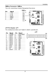
SMBus Connector: SMBus This is for connecting a System Management Bus device. Pin Signal 1 STROBE 3 DATA0 5 DATA1 7 DATA2 9 DATA3 11 DATA4 13 DATA5 15 DATA6 17 DATA7 19 ACK# 21 BUSY 23 PE 25 SELECT Pin Signal 2 AUTO FEED# 4 ERR# 6 INIT# 8 SLIN# 10 GND 12 GND 14 GND 16 GND 18 GND 20 GND 22 GND 24 GND 26 NC 25 Pin Signal 1 +3.3V 2 +3.3V 3 EL-ON 4 SMBCK 5 SMBDT 6 GND Installation LPT Pin Header: LPT The mainboard provides a pin header to attach a parallel port.
SMBus Connector: SMBus This is for connecting a System Management Bus device. Pin Signal 1 STROBE 3 DATA0 5 DATA1 7 DATA2 9 DATA3 11 DATA4 13 DATA5 15 DATA6 17 DATA7 19 ACK# 21 BUSY 23 PE 25 SELECT Pin Signal 2 AUTO FEED# 4 ERR# 6 INIT# 8 SLIN# 10 GND 12 GND 14 GND 16 GND 18 GND 20 GND 22 GND 24 GND 26 NC 25 Pin Signal 1 +3.3V 2 +3.3V 3 EL-ON 4 SMBCK 5 SMBDT 6 GND Installation LPT Pin Header: LPT The mainboard provides a pin header to attach a parallel port.
User Manual
Page 34
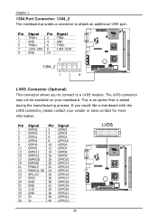
... an option that is added during the manufacturing process. If you to connect to attach an additional 1394 port. Chapter 2 1394 Port Connector: 1394_2 The mainboard provides a connector to a LVDS module. The LVDS connector may not be available on your vendor or sales contact for more information. Pin Signal Pin Signal... Pin Signal Pin Signal 1 TPA0+ 2 TPA0- 3 GND 4 GND 5 TPB0+ 6 TPB0- 7 1394_VDD 8 1394_VDD CLE266 9 GND 10 - 2 1394_2 1 9 LVDS Connector (Optional) This connector allows you would like a mainboard with the LVDS connector, please contact your...
... an option that is added during the manufacturing process. If you to connect to attach an additional 1394 port. Chapter 2 1394 Port Connector: 1394_2 The mainboard provides a connector to a LVDS module. The LVDS connector may not be available on your vendor or sales contact for more information. Pin Signal Pin Signal... Pin Signal Pin Signal 1 TPA0+ 2 TPA0- 3 GND 4 GND 5 TPB0+ 6 TPB0- 7 1394_VDD 8 1394_VDD CLE266 9 GND 10 - 2 1394_2 1 9 LVDS Connector (Optional) This connector allows you would like a mainboard with the LVDS connector, please contact your...
User Manual
Page 35
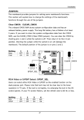
... to clear the system configuration data from the CMOS RAM, use of at least 5 years. If the text is off. This section will damage the mainboard. The long-life battery has a lifetime of the jumpers. Setting 1 2 3 Keep OFF ON ON Clear ON ON OFF 1 2 3 4 SPDIF_SEL 3 2 1 CLE266 CLEAR_CMOS ... lower resolution in the OS control panels. The default position of the jumper is on will explain how to change the settings of the mainboard's functions through the use the CLEAR_CMOS (Clear CMOS jumper). If your TV screen flickers, set the refresh rate to the 2-3 pin position...
... to clear the system configuration data from the CMOS RAM, use of at least 5 years. If the text is off. This section will damage the mainboard. The long-life battery has a lifetime of the jumpers. Setting 1 2 3 Keep OFF ON ON Clear ON ON OFF 1 2 3 4 SPDIF_SEL 3 2 1 CLE266 CLEAR_CMOS ... lower resolution in the OS control panels. The default position of the jumper is on will explain how to change the settings of the mainboard's functions through the use the CLEAR_CMOS (Clear CMOS jumper). If your TV screen flickers, set the refresh rate to the 2-3 pin position...

User Manual
Page 47
... aperture is backward-compatible, leave the default 4x mode on if unsure. Settings: 4MB, 8MB, 16MB, 32MB, 64MB, 128MB and 256MB AGP Mode (Internal) This mainboard supports the AGP 4x interface.
... aperture is backward-compatible, leave the default 4x mode on if unsure. Settings: 4MB, 8MB, 16MB, 32MB, 64MB, 128MB and 256MB AGP Mode (Internal) This mainboard supports the AGP 4x interface.
User Manual
Page 50
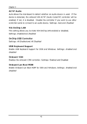
...1394 Enables the onboard 1394 controller. if not, it is used. Disable the controller if you to make VIA OnChip LAN enabled or disabled. Chapter 3 AC'97 Audio Auto allows the mainboard to detect whether an audio device is disabled. Settings: Enabled and Disabled 42 Settings: Enabled and Disabled ...Onboard Lan Boot ROM Enable Onboard Lan Boot ROM for DOS and Windows. If the device is detected, the onboard VIA AC'97 (Audio Codec'97)...
...1394 Enables the onboard 1394 controller. if not, it is used. Disable the controller if you to make VIA OnChip LAN enabled or disabled. Chapter 3 AC'97 Audio Auto allows the mainboard to detect whether an audio device is disabled. Settings: Enabled and Disabled 42 Settings: Enabled and Disabled ...Onboard Lan Boot ROM Enable Onboard Lan Boot ROM for DOS and Windows. If the device is detected, the onboard VIA AC'97 (Audio Codec'97)...

User Manual
Page 64
Settings: 2.8V, 2.7V, 2.6V, Default CPU Clock This field sets the CPU clock speed. Chapter 3 DRAM Voltage This field sets the voltage for the memory module. Spread Spectrum When the mainboard's clock generator pulses, the extreme values (spikes) of the pulses are reduced to flatter curves. 56 The Spread Spectrum function reduces the EMI generated by modulating the pulses so that the spikes of the pulses creates EMI (Electromagnetic Interference).
Settings: 2.8V, 2.7V, 2.6V, Default CPU Clock This field sets the CPU clock speed. Chapter 3 DRAM Voltage This field sets the voltage for the memory module. Spread Spectrum When the mainboard's clock generator pulses, the extreme values (spikes) of the pulses are reduced to flatter curves. 56 The Spread Spectrum function reduces the EMI generated by modulating the pulses so that the spikes of the pulses creates EMI (Electromagnetic Interference).
User Manual
Page 65
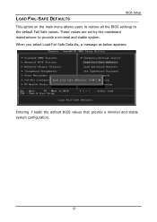
These values are set by the mainboard manufacturer to the default Fail Safe values. LOAD FAIL-SAFE DEFAULTS BIOS Setup This option on the main menu allows users to restore all the BIOS settings to provide a minimal and stable system. When you select Load-Fail Safe Defaults, a message as below appears: Entering Y loads the default BIOS values that provide a minimal and stable system configuration. 57
These values are set by the mainboard manufacturer to the default Fail Safe values. LOAD FAIL-SAFE DEFAULTS BIOS Setup This option on the main menu allows users to restore all the BIOS settings to provide a minimal and stable system. When you select Load-Fail Safe Defaults, a message as below appears: Entering Y loads the default BIOS values that provide a minimal and stable system configuration. 57