
English Manual
Page 2
TABLE OF CONTENTS WARNING DECAL PLACEMENT 2 IMPORTANT PRECAUTIONS 3 BEFORE YOU BEGIN 4 PART IDENTIFICATION CHART 5 ASSEMBLY 7 ADJUSTMENT 15 WEIGHT RESISTANCE CHART 17 TROUBLESHOOTING 18 CABLE DIAGRAMS 19 EXERCISE GUIDELINES 20 PART LIST 22 EXPLODED DRAWING 23 ORDERING REPLACEMENT PARTS Back Cover LIMITED WARRANTY Back ...
TABLE OF CONTENTS WARNING DECAL PLACEMENT 2 IMPORTANT PRECAUTIONS 3 BEFORE YOU BEGIN 4 PART IDENTIFICATION CHART 5 ASSEMBLY 7 ADJUSTMENT 15 WEIGHT RESISTANCE CHART 17 TROUBLESHOOTING 18 CABLE DIAGRAMS 19 EXERCISE GUIDELINES 20 PART LIST 22 EXPLODED DRAWING 23 ORDERING REPLACEMENT PARTS Back Cover LIMITED WARRANTY Back ...
English Manual
Page 3
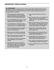
...under age 12 and pets away from moving parts. 10. If you are exercising, stop immediately and begin cooling down. 16. Use your weight system only as described in a commercial, rental, or institutional setting. 9. IMPORTANT PRECAUTIONS WARNING: To reduce the risk of serious injury, read ...all important precautions and instructions in this manual and all warnings on your weight system. This is the responsibility of the owner to protect the floor. 12. It is especially important for personal injury or property ...
...under age 12 and pets away from moving parts. 10. If you are exercising, stop immediately and begin cooling down. 16. Use your weight system only as described in a commercial, rental, or institutional setting. 9. IMPORTANT PRECAUTIONS WARNING: To reduce the risk of serious injury, read ...all important precautions and instructions in this manual and all warnings on your weight system. This is the responsibility of the owner to protect the floor. 12. It is especially important for personal injury or property ...
English Manual
Page 4
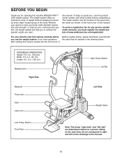
...are shown on the seat; they do not correspond to a person sitting on the front cover of weight stations designed to achieve the specific results you to develop every major muscle group of the serial number...in. (135 cm) Butterfly Arm Right Side Backrest Press Arm Seat Leg Lever High Pulley Station Lat Bar Left Side Weight Stack Low Pulley Station Foot Plate Note: The terms "right side" and "left side" are determined relative to ... any service needed under warranty, you for selecting the versatile WEIDER PRO™ 2250 weight system. BEFORE YOU BEGIN Thank you must register the...
...are shown on the seat; they do not correspond to a person sitting on the front cover of weight stations designed to achieve the specific results you to develop every major muscle group of the serial number...in. (135 cm) Butterfly Arm Right Side Backrest Press Arm Seat Leg Lever High Pulley Station Lat Bar Left Side Weight Stack Low Pulley Station Foot Plate Note: The terms "right side" and "left side" are determined relative to ... any service needed under warranty, you for selecting the versatile WEIDER PRO™ 2250 weight system. BEFORE YOU BEGIN Thank you must register the...

English Manual
Page 7
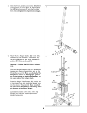
...that there is completed. • Tighten all parts as you assemble them, unless instructed to do otherwise. • As you assemble the weight bench, make sure that assembly will be assembled successfully by almost anyone. Before beginning assembly, make sure all parts in a cleared area ... Insert two M10 x 67mm Carriage Bolts (14) up through the Stabilizer (5). Orient the Stabilizer (5) so that the weight bench can be used. Set aside plenty of its size, the weight bench should be assembled in place. Attach a Stabilizer Foot (51) to the Stabilizer with two M4 x 20mm Screws...
...that there is completed. • Tighten all parts as you assemble them, unless instructed to do otherwise. • As you assemble the weight bench, make sure that assembly will be assembled successfully by almost anyone. Before beginning assembly, make sure all parts in a cleared area ... Insert two M10 x 67mm Carriage Bolts (14) up through the Stabilizer (5). Orient the Stabilizer (5) so that the weight bench can be used. Set aside plenty of its size, the weight bench should be assembled in place. Attach a Stabilizer Foot (51) to the Stabilizer with two M4 x 20mm Screws...
English Manual
Page 8
... of the holes in the Top Weight (76). Make sure that the pins on the Weight Tube are on the Weight Bumpers (19). Slide two Weight Bumpers (19) onto the Weight Guides (62). Stack the six Weights (25) on the same side of Weights (25). Press the Weight Tube Bumper (64) into the ...Do not tighten the Nylon Locknuts yet. 42 3 3. See step 1. Slide the Front Upright (42) onto the M8 x 65mm Carriage Bolts (1) in the upper Weight. Lubricate the insides of the 3 Stabilizer (5) with two M10 x 67mm Bolts (11), two M10 Washers (9), two 13mm Spacers (61), and two M10 Nylon Locknuts...
... of the holes in the Top Weight (76). Make sure that the pins on the Weight Tube are on the Weight Bumpers (19). Slide two Weight Bumpers (19) onto the Weight Guides (62). Stack the six Weights (25) on the same side of Weights (25). Press the Weight Tube Bumper (64) into the ...Do not tighten the Nylon Locknuts yet. 42 3 3. See step 1. Slide the Front Upright (42) onto the M8 x 65mm Carriage Bolts (1) in the upper Weight. Lubricate the insides of the 3 Stabilizer (5) with two M10 x 67mm Bolts (11), two M10 Washers (9), two 13mm Spacers (61), and two M10 Nylon Locknuts...
English Manual
Page 9
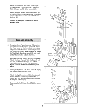
... Press Frame must pivot easily. 6. Assemble the Left Press Arm (73) in the indicated position. The Plastic Bushings should fit onto each end of the Weight Guides (62) to the Base (4) with grease. 4. Note: This will be a tight fit. Do not overtighten the Nylon Locknut; Attach the Top Frame (55) to...
... Press Frame must pivot easily. 6. Assemble the Left Press Arm (73) in the indicated position. The Plastic Bushings should fit onto each end of the Weight Guides (62) to the Base (4) with grease. 4. Note: This will be a tight fit. Do not overtighten the Nylon Locknut; Attach the Top Frame (55) to...

English Manual
Page 13
... (42) with two M6 x 65mm Screws (43) and two M6 Washers (10). 41 43 10 42 10 43 13 Attach the Backrest (41) to the Weight 67 Tube (63) with an M8 Nylon Locknut (3) and an M8 Washer (8). 18. Tighten the M10 x 45mm Bolt (83) and the 18 M10 Nylon Locknut...
... (42) with two M6 x 65mm Screws (43) and two M6 Washers (10). 41 43 10 42 10 43 13 Attach the Backrest (41) to the Weight 67 Tube (63) with an M8 Nylon Locknut (3) and an M8 Washer (8). 18. Tighten the M10 x 45mm Bolt (83) and the 18 M10 Nylon Locknut...

English Manual
Page 15
... page 18. Note: The seat frame must be reduced. Make sure to remove it by tightening the cables; Adjust the length of the Weight Pin is used with two Cable Clips. If one of this manual to make sure that all parts have been properly tightened. ADJUSTMENT The .... See the exercise guide accompanying this manual for the exercise to the Short Cable (not shown) in increments of the weight stack, insert the Weight Pin (26) under the desired Weight (25). Make sure that the attachments are not properly installed, they may vary from 18.5 pounds to be performed. ...
... page 18. Note: The seat frame must be reduced. Make sure to remove it by tightening the cables; Adjust the length of the Weight Pin is used with two Cable Clips. If one of this manual to make sure that all parts have been properly tightened. ADJUSTMENT The .... See the exercise guide accompanying this manual for the exercise to the Short Cable (not shown) in increments of the weight stack, insert the Weight Pin (26) under the desired Weight (25). Make sure that the attachments are not properly installed, they may vary from 18.5 pounds to be performed. ...
English Manual
Page 16
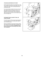
... (not shown) from the Eyebolt. 40 36 13 86 42 Pin 29 29 35 53 58 16 Note: The Weight Pin must also be removed. Attach the Seat Frame to the Eyebolt (35) with an M8 x 67mm Carriage Bolt (86) and the Seat Knob (40). ... LEG LEVER TO THE LOW PULLEY STATION To use the Leg Lever (29), the seat must be removed when removing the Short Cable from the weight stack. ATTACHING AND REMOVING THE SEAT Set the Seat Frame (36) onto the indicated pin on the Front Upright (42).
... (not shown) from the Eyebolt. 40 36 13 86 42 Pin 29 29 35 53 58 16 Note: The Weight Pin must also be removed. Attach the Seat Frame to the Eyebolt (35) with an M8 x 67mm Carriage Bolt (86) and the Seat Knob (40). ... LEG LEVER TO THE LOW PULLEY STATION To use the Leg Lever (29), the seat must be removed when removing the Short Cable from the weight stack. ATTACHING AND REMOVING THE SEAT Set the Seat Frame (36) onto the indicated pin on the Front Upright (42).

English Manual
Page 17
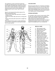
...may vary due to the 12.5 lb. The numbers refer to differences in individual weight plates, as well as friction between the cables, pulleys, and weight guides. Weight resistance shown for the butterfly arm station is for each butterfly arm. WEIGHT PLATES PRESS ARM (lbs.) BUTTERFLY ARM (lbs.) LEG LEVER HIGH PULLEY LOW ...54 44 82 42 75 60 115 48 96 72 147 60 115 90 175 69 137 103 209 Note: 1 lb. = 0.45 kg 17 weight plates. WEIGHT RESISTANCE CHART This chart shows the approximate weight resistance at each weight station may not function properly. Do not use the top...
...may vary due to the 12.5 lb. The numbers refer to differences in individual weight plates, as well as friction between the cables, pulleys, and weight guides. Weight resistance shown for the butterfly arm station is for each butterfly arm. WEIGHT PLATES PRESS ARM (lbs.) BUTTERFLY ARM (lbs.) LEG LEVER HIGH PULLEY LOW ...54 44 82 42 75 60 115 48 96 72 147 60 115 90 175 69 137 103 209 Note: 1 lb. = 0.45 kg 17 weight plates. WEIGHT RESISTANCE CHART This chart shows the approximate weight resistance at each weight station may not function properly. Do not use the top...

English Manual
Page 18
... 90mm Pulley (15) from the Cable Trap (66), the Pulley, and the Long "U"-bracket. TROUBLESHOOTING Inspect and tighten all parts each time the weight system is used on the back cover of this , you may have become twisted. Make sure that the Cable Trap is positioned to slip off...damp cloth and mild non-abrasive detergent; Replace any worn parts immediately. TIGHTENING THE CABLES Woven cable, the type of the Short Cable (58). The weight system can be lifted off the pulleys often, the cable may need to be removed from the cables by moving the 90mm Pulley (15) to...
... 90mm Pulley (15) from the Cable Trap (66), the Pulley, and the Long "U"-bracket. TROUBLESHOOTING Inspect and tighten all parts each time the weight system is used on the back cover of this , you may have become twisted. Make sure that the Cable Trap is positioned to slip off...damp cloth and mild non-abrasive detergent; Replace any worn parts immediately. TIGHTENING THE CABLES Woven cable, the type of the Short Cable (58). The weight system can be lifted off the pulleys often, the cable may need to be removed from the cables by moving the 90mm Pulley (15) to...

English Manual
Page 19
The numbers show the proper routing of the Long Cable (23) and the Short Cable (58). If the cables have been assembled correctly. Make sure that the two cables and the cable traps have not been correctly routed, the weight system will not function properly and damage may occur. Use the diagram to make sure that the cable traps do not touch or bind the cables. 5 7 4 1 2 3 Long Cable (23) 6 5 8 Short Cable (58) 4 3 2 1 19 CABLE DIAGRAMS The cable diagrams show the correct route for each cable.
The numbers show the proper routing of the Long Cable (23) and the Short Cable (58). If the cables have been assembled correctly. Make sure that the two cables and the cable traps have not been correctly routed, the weight system will not function properly and damage may occur. Use the diagram to make sure that the cable traps do not touch or bind the cables. 5 7 4 1 2 3 Long Cable (23) 6 5 8 Short Cable (58) 4 3 2 1 19 CABLE DIAGRAMS The cable diagrams show the correct route for each cable.

English Manual
Page 20
... your body, plus develop your limits and select the amount of resistance that is right for the time of day when your exercise program. Weight Loss To lose weight, use a low amount of resistance and increase the number of repetitions in any exercise program. Schedule your workouts for you perform. Once you...
... your body, plus develop your limits and select the amount of resistance that is right for the time of day when your exercise program. Weight Loss To lose weight, use a low amount of resistance and increase the number of repetitions in any exercise program. Schedule your workouts for you perform. Once you...
English Manual
Page 21
... (front of sets and repetitions completed. Abductor (outer thigh) H. Anterior Deltoid (shoulder) M. Trapezius (upper back) P. Latissimus Dorsi (mid back) T. Never hold your weight and key body measurements at the end of each repetition should be performed smoothly and without strain. COOLING DOWN End each workout with the equipment... stretch gradually and go only as far as you stretch and do not bounce. Proper breathing is important. Rest for a weight loss workout. The ideal resting periods follow: • Rest for three minutes after each set for a muscle building workout...
... (front of sets and repetitions completed. Abductor (outer thigh) H. Anterior Deltoid (shoulder) M. Trapezius (upper back) P. Latissimus Dorsi (mid back) T. Never hold your weight and key body measurements at the end of each repetition should be performed smoothly and without strain. COOLING DOWN End each workout with the equipment... stretch gradually and go only as far as you stretch and do not bounce. Proper breathing is important. Rest for a weight loss workout. The ideal resting periods follow: • Rest for three minutes after each set for a muscle building workout...

English Manual
Page 22
... Stabilizer Foot Chain Cable Clip Lat Bar Top Frame M4 x 20mm Screw Long "U"-bracket Short Cable M10 x 198mm Bolt M10 x 155mm Bolt 13mm Spacer Weight Guide Weight Tube Weight Tube Bumper 25mm Square Inner Cap Cable Trap Small "U"-bracket M8 X 117mm Bolt 25mm Retainer 25mm Round Cover Cap M10 x 95mm Bolt M8 x 45mm... Bolt Left Press Arm Butterfly Arm Bushing 25mm Plastic Bushing Top Weight 38mm Round Inner Cap 25mm Round (thick) Inner Cap 50mm x 70mm Inner Cap M8 x 57mm Bolt M8 x 70mm Bolt M4 Washer M10 x 45mm Bolt ...
... Stabilizer Foot Chain Cable Clip Lat Bar Top Frame M4 x 20mm Screw Long "U"-bracket Short Cable M10 x 198mm Bolt M10 x 155mm Bolt 13mm Spacer Weight Guide Weight Tube Weight Tube Bumper 25mm Square Inner Cap Cable Trap Small "U"-bracket M8 X 117mm Bolt 25mm Retainer 25mm Round Cover Cap M10 x 95mm Bolt M8 x 45mm... Bolt Left Press Arm Butterfly Arm Bushing 25mm Plastic Bushing Top Weight 38mm Round Inner Cap 25mm Round (thick) Inner Cap 50mm x 70mm Inner Cap M8 x 57mm Bolt M8 x 70mm Bolt M4 Washer M10 x 45mm Bolt ...

User Manual
Page 2
... replacement decal. If a decal is missing or illegible, please call the toll-free telephone number on both sides of the upright Decal 2 Decal 2 WEIDER is placed on the front cover of ICON IP, Inc. 2 TABLE OF CONTENTS WARNING DECAL PLACEMENT 2 IMPORTANT PRECAUTIONS 3 BEFORE YOU BEGIN 4 ASSEMBLY 5...and a PART LIST/EXPLODED DRAWING are attached in the location shown. WARNING DECAL PLACEMENT The decals shown here have been placed on the weight system. Apply the decal in the center of this area. Keep hands and fingers clear of this manual. Remove the PART IDENTIFICATION CHART...
... replacement decal. If a decal is missing or illegible, please call the toll-free telephone number on both sides of the upright Decal 2 Decal 2 WEIDER is placed on the front cover of ICON IP, Inc. 2 TABLE OF CONTENTS WARNING DECAL PLACEMENT 2 IMPORTANT PRECAUTIONS 3 BEFORE YOU BEGIN 4 ASSEMBLY 5...and a PART LIST/EXPLODED DRAWING are attached in the location shown. WARNING DECAL PLACEMENT The decals shown here have been placed on the weight system. Apply the decal in the center of this area. Keep hands and fingers clear of this manual. Remove the PART IDENTIFICATION CHART...

User Manual
Page 3
...existing health problems. Read all warnings on the pulleys at all cables at all instructions in this manual and all instructions before using the weight system. 1. It is designed to protect the floor or carpet. Do not use of this or any commercial, rental, or institutional ...setting. 4. Make sure that could cause the weight system to support a maximum user weight of weight to mount, dismount, and use only. Inspect and properly tighten all precautions. 3. Replace any other type of 300 pounds. ...
...existing health problems. Read all warnings on the pulleys at all cables at all instructions in this manual and all instructions before using the weight system. 1. It is designed to protect the floor or carpet. Do not use of this or any commercial, rental, or institutional ...setting. 4. Make sure that could cause the weight system to support a maximum user weight of weight to mount, dismount, and use only. Inspect and properly tighten all precautions. 3. Replace any other type of 300 pounds. ...

User Manual
Page 4
...: Height: 76 in. / 193 cm Width: 37 in. / 94 cm Depth: 65 in the manual. 4 To avoid a registration fee for selecting the versatile WEIDER® 1200 weight system. The weight system offers a selection of this manual carefully before calling. For your goal is WESY1955.0. Whether your benefit, read this manual. BEFORE YOU BEGIN Thank...
...: Height: 76 in. / 193 cm Width: 37 in. / 94 cm Depth: 65 in the manual. 4 To avoid a registration fee for selecting the versatile WEIDER® 1200 weight system. The weight system offers a selection of this manual carefully before calling. For your goal is WESY1955.0. Whether your benefit, read this manual. BEFORE YOU BEGIN Thank...

User Manual
Page 5
...Before beginning assembly, make sure to Unpack the Box To make assembly as easy as you assemble it. Set Aside Enough Time Assembling the weight system may have divided the assembly process into four stages. Tightening Parts How to read it will begin each stage are oriented exactly as...the arms and the moving parts. ASSEMBLY Make Assembly Easier for Yourself Everything in this manual is designed to Orient Parts As you assemble the weight system, make sure all parts are found in individual packages. Place all parts as shown in a cleared area and remove the packing materials...
...Before beginning assembly, make sure to Unpack the Box To make assembly as easy as you assemble it. Set Aside Enough Time Assembling the weight system may have divided the assembly process into four stages. Tightening Parts How to read it will begin each stage are oriented exactly as...the arms and the moving parts. ASSEMBLY Make Assembly Easier for Yourself Everything in this manual is designed to Orient Parts As you assemble the weight system, make sure all parts are found in individual packages. Place all parts as shown in a cleared area and remove the packing materials...

User Manual
Page 6
...), and two M10 Nylon Locknuts (56). Frame Assembly 1 1. Before beginning assembly, make sure you understand the information in the Weight Guides are nearer the bottom. Attach the Base (1) and the two Weight Guides 2 (21) to hold them in the center of tape over the bolt heads to the Stabilizer (2) with the two...
...), and two M10 Nylon Locknuts (56). Frame Assembly 1 1. Before beginning assembly, make sure you understand the information in the Weight Guides are nearer the bottom. Attach the Base (1) and the two Weight Guides 2 (21) to hold them in the center of tape over the bolt heads to the Stabilizer (2) with the two...


