

English Manual
Page 2
TABLE OF CONTENTS WARNING DECAL PLACEMENT 3 IMPORTANT PRECAUTIONS 4 BEFORE YOU BEGIN 5 ASSEMBLY 6 ADJUSTMENTS 26 WEIGHT RESISTANCE CHART 28 CABLE DIAGRAMS 29 TROUBLE SHOOTING 31 EXERCISE GUIDELINES 32 ORDERING REPLACEMENT PARTS Back Cover LIMITED WARRANTY Back Cover Note: A PART IDENTIFICATION CHART and a PART LIST/EXPLODED DRAWING are attached in the center of ICON Health & Fitness, Inc. 2 Remove the PART IDENTIFICATION CHART and PART LIST/EXPLODED DRAWING before beginning assembly. WEIDER is a registered trademark of this manual.
TABLE OF CONTENTS WARNING DECAL PLACEMENT 3 IMPORTANT PRECAUTIONS 4 BEFORE YOU BEGIN 5 ASSEMBLY 6 ADJUSTMENTS 26 WEIGHT RESISTANCE CHART 28 CABLE DIAGRAMS 29 TROUBLE SHOOTING 31 EXERCISE GUIDELINES 32 ORDERING REPLACEMENT PARTS Back Cover LIMITED WARRANTY Back Cover Note: A PART IDENTIFICATION CHART and a PART LIST/EXPLODED DRAWING are attached in the center of ICON Health & Fitness, Inc. 2 Remove the PART IDENTIFICATION CHART and PART LIST/EXPLODED DRAWING before beginning assembly. WEIDER is a registered trademark of this manual.

English Manual
Page 3
Apply the decal in the location shown. Decal 3 3 Decal 2 • Keep clear of this area. Mountain Time, to order a free replacement decal. If a decal is missing or illegible, please call our Customer Service Department toll-free at 1-800-999-3756, Monday through Friday, 6 a.m. Decal 2 Decal 3 Decal 1 Decal 2 Decal 3 Decal 1 Keep hands and fingers clear of this area. until 6 p.m. WARNING DECAL PLACEMENT The decals shown here have been placed on the weight system.
Apply the decal in the location shown. Decal 3 3 Decal 2 • Keep clear of this area. Mountain Time, to order a free replacement decal. If a decal is missing or illegible, please call our Customer Service Department toll-free at 1-800-999-3756, Monday through Friday, 6 a.m. Decal 2 Decal 3 Decal 1 Decal 2 Decal 3 Decal 1 Keep hands and fingers clear of this area. until 6 p.m. WARNING DECAL PLACEMENT The decals shown here have been placed on the weight system.

English Manual
Page 4
... when performing an exercise that does not use of this or any commercial, rental, or institutional setting. 4. Make sure that could cause the weight system to tip. 12. Always stand on the foot plate when performing an exercise that the cables remain on the pulleys at a time. 10. ...Never release the butterfly arms, leg lever, lat bar, leg press, or accessories while weights are exercising, stop immediately and begin cooling down. Always wear athletic shoes for personal injury or property damage sustained by only one person at all...
... when performing an exercise that does not use of this or any commercial, rental, or institutional setting. 4. Make sure that could cause the weight system to tip. 12. Always stand on the foot plate when performing an exercise that the cables remain on the pulleys at a time. 10. ...Never release the butterfly arms, leg lever, lat bar, leg press, or accessories while weights are exercising, stop immediately and begin cooling down. Always wear athletic shoes for personal injury or property damage sustained by only one person at all...

English Manual
Page 5
... tollfree at 1-800-999-3756, Monday through Friday, 6 a.m. Mountain Time (excluding holidays). To help you for selecting the versatile WEIDER® CLUB C4800 weight system. ASSEMBLED DIMENSIONS: Height: 82 in. For your cardiovascular system, the weight system will help us assist you have additional ques- Shroud Backrest Lat Bar High Pulley Station AB Pulley Station...
... tollfree at 1-800-999-3756, Monday through Friday, 6 a.m. Mountain Time (excluding holidays). To help you for selecting the versatile WEIDER® CLUB C4800 weight system. ASSEMBLED DIMENSIONS: Height: 82 in. For your cardiovascular system, the weight system will help us assist you have additional ques- Shroud Backrest Lat Bar High Pulley Station AB Pulley Station...

English Manual
Page 6
... will also need grease or petroleum jelly, a small amount of ratchet wrenches. To help of the weight system. If a part is enough room to assemble the weight system over a couple of the weight system in the location where it will save you have the following tools: • Two adjustable wrenches... Assembly-During this stage you have a socket set, a set of open the parts bag for each stage to the many features of the weight system, the assembly process will assemble the seats and the backrests. 6 Seat Assembly-During the final stage you will attach the cables and pulleys...
... will also need grease or petroleum jelly, a small amount of ratchet wrenches. To help of the weight system. If a part is enough room to assemble the weight system over a couple of the weight system in the location where it will save you have the following tools: • Two adjustable wrenches... Assembly-During this stage you have a socket set, a set of open the parts bag for each stage to the many features of the weight system, the assembly process will assemble the seats and the backrests. 6 Seat Assembly-During the final stage you will attach the cables and pulleys...
English Manual
Page 8
... 12.5mm Spacers (69), and two M10 Nylon Locknuts (101). 46 88 6 19 18 101 99 69 99 1 69 99 69 99 80 8 Attach the Weight Guides to the Butterfly Upright (2) with two M10 x 65mm Bolts (80), four M10 Washers (99), four 12.5mm Spacers (69), and two M10 Nylon Locknuts...), an M10 Washer (99), and three M10 Nylon Locknuts (101). Do not tighten the Locknuts yet. 99 101 82 101 46 101 4. Insert the two Weight Guides with two M10 x 65mm Carriage Bolts (88) and two M10 Nylon Locknuts (101). 3. Press two 50mm x 75mm 3 Inner Caps (46) into the indicated holes...
... 12.5mm Spacers (69), and two M10 Nylon Locknuts (101). 46 88 6 19 18 101 99 69 99 1 69 99 69 99 80 8 Attach the Weight Guides to the Butterfly Upright (2) with two M10 x 65mm Bolts (80), four M10 Washers (99), four 12.5mm Spacers (69), and two M10 Nylon Locknuts...), an M10 Washer (99), and three M10 Nylon Locknuts (101). Do not tighten the Locknuts yet. 99 101 82 101 46 101 4. Insert the two Weight Guides with two M10 x 65mm Carriage Bolts (88) and two M10 Nylon Locknuts (101). 3. Press two 50mm x 75mm 3 Inner Caps (46) into the indicated holes...

English Manual
Page 9
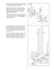
... the pin on the side shown. 5. Slide two Weight Bumpers (71) onto the Weight 5 Guides (18). Slide eight Weights (22) onto the Weight Guides (18). Press a Weight Tube Bumper (54) into the Weights (22). Make sure the Weights are oriented with grease. Press a Weight Tube Bumper (54) into the Weights (22). Lubricate the indicated holes in the other Top...
... the pin on the side shown. 5. Slide two Weight Bumpers (71) onto the Weight 5 Guides (18). Slide eight Weights (22) onto the Weight Guides (18). Press a Weight Tube Bumper (54) into the Weights (22). Make sure the Weights are oriented with grease. Press a Weight Tube Bumper (54) into the Weights (22). Lubricate the indicated holes in the other Top...
English Manual
Page 10
... Seat Frame (8). Then, tighten the handle. 45 101 19 47 9 101 82 51 2 18 8 59 44 43 4 9. Attach the Top Frame (9) to the Weight Guides (18, 19) with two M10 x 75mm Bolts (82) and two M10 Nylon Locknuts (101). Attach the Top Frame (9) to the Butterfly Upright (2) with four... Angled Outer Cap (43) onto the other end of the Seat Adjustment Frame (4). Attach the Seat Adjustment Frame (4) to loosen it engage one of the Weight Guides (18, 19). Tighten the M10 Nylon Locknuts (101) used in the Seat Adjustment Frame. Tighten a "T"-handle (59) into the Sliding Seat Frame....
... Seat Frame (8). Then, tighten the handle. 45 101 19 47 9 101 82 51 2 18 8 59 44 43 4 9. Attach the Top Frame (9) to the Weight Guides (18, 19) with two M10 x 75mm Bolts (82) and two M10 Nylon Locknuts (101). Attach the Top Frame (9) to the Butterfly Upright (2) with four... Angled Outer Cap (43) onto the other end of the Seat Adjustment Frame (4). Attach the Seat Adjustment Frame (4) to loosen it engage one of the Weight Guides (18, 19). Tighten the M10 Nylon Locknuts (101) used in the Seat Adjustment Frame. Tighten a "T"-handle (59) into the Sliding Seat Frame....

English Manual
Page 14
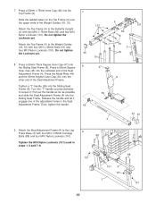
... M10 x 65mm Bolt (80), two M10 Washers (99), two 12.5mm Spacers (69), and an M10 Nylon Locknut (101). 23. Set the tether on the Weight Tube. Tighten the Nut against the 50mm Washer (95). 58 23 62 98 95 14 Route the Lat Cable (62) up through the Top Frame... (9) and over a 100mm Pulley (38) and down through the Top Frame (9). Set a 50mm Washer (95) on a Weight Pin (98) over a 100mm Pulley (38), and back down through the Top Frame. Attach the Pulley inside the Top Frame with an M10 x 65mm Bolt...
... M10 x 65mm Bolt (80), two M10 Washers (99), two 12.5mm Spacers (69), and an M10 Nylon Locknut (101). 23. Set the tether on the Weight Tube. Tighten the Nut against the 50mm Washer (95). 58 23 62 98 95 14 Route the Lat Cable (62) up through the Top Frame... (9) and over a 100mm Pulley (38) and down through the Top Frame (9). Set a 50mm Washer (95) on a Weight Pin (98) over a 100mm Pulley (38), and back down through the Top Frame. Attach the Pulley inside the Top Frame with an M10 x 65mm Bolt...

English Manual
Page 15
... M10 x 65mm Bolt (80), two M10 Washers (99), two 12.5mm Spacers (69), and an M10 Nylon Locknut (101). 28. Set the tether on the Weight Tube. Make sure the Cable Trap is oriented to the indicated hole in the groove of the Pulley. 27. Thread an M12 Nut (58) all... the way onto the Upper Short Stack Cable (63). 25. Set a 50mm Washer (95) on the other Weight Pin (98) over 29 the Short Weight Tube (24). Route the Upper Short Stack Cable (63) over a 100mm Pulley (38). Screw the Cable partway into the Short...
... M10 x 65mm Bolt (80), two M10 Washers (99), two 12.5mm Spacers (69), and an M10 Nylon Locknut (101). 28. Set the tether on the Weight Tube. Make sure the Cable Trap is oriented to the indicated hole in the groove of the Pulley. 27. Thread an M12 Nut (58) all... the way onto the Upper Short Stack Cable (63). 25. Set a 50mm Washer (95) on the other Weight Pin (98) over 29 the Short Weight Tube (24). Route the Upper Short Stack Cable (63) over a 100mm Pulley (38). Screw the Cable partway into the Short...
English Manual
Page 17
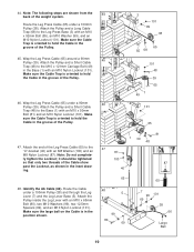
... "U"-bracket (40) with an M8 Washer (100) and an 67 M8 Nylon Locknut (87). it should be tightened so that only two threads of the weight system. Note: The following steps are shown from the 38 back of the Cable show 40 past the Locknut, as shown in the groove of...
... "U"-bracket (40) with an M8 Washer (100) and an 67 M8 Nylon Locknut (87). it should be tightened so that only two threads of the weight system. Note: The following steps are shown from the 38 back of the Cable show 40 past the Locknut, as shown in the groove of...
English Manual
Page 18
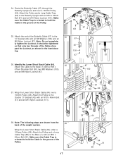
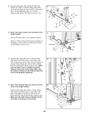
...) to the Base (1) with an M10 x 45mm Bolt (51), an M10 Washer (99), and an M10 Nylon Locknut (101). 41. Attach the Pulley to the Weight Plate (20) with an M8 x 67mm Shoulder Bolt (90), two M8 Washers (100), and an M8 Nylon Locknut (87). 42 100 87 43. Identify the... Pulley and a Short Cable Trap (48) to the Rear Press Arm (13) with an M10 x 45mm Bolt (51). Locate the Weight Plate (20) that is oriented to hold the Cable in the groove of the Bottom Weight (21). Attach the Cable to the bottom of the Pulley. 1 64 51 48 39 40.
...) to the Base (1) with an M10 x 45mm Bolt (51), an M10 Washer (99), and an M10 Nylon Locknut (101). 41. Attach the Pulley to the Weight Plate (20) with an M8 x 67mm Shoulder Bolt (90), two M8 Washers (100), and an M8 Nylon Locknut (87). 42 100 87 43. Identify the... Pulley and a Short Cable Trap (48) to the Rear Press Arm (13) with an M10 x 45mm Bolt (51). Locate the Weight Plate (20) that is oriented to hold the Cable in the groove of the Bottom Weight (21). Attach the Cable to the bottom of the Pulley. 1 64 51 48 39 40.
English Manual
Page 19
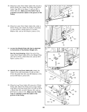
... the Leg Press Cable (65) under a 100mm Pulley (38). Make sure the Cable Trap is oriented to hold the Cable in the groove of the weight system. Make sure the Cable Trap is oriented to hold the Cable in the groove of the Cable show past the Locknut, as shown in...
... the Leg Press Cable (65) under a 100mm Pulley (38). Make sure the Cable Trap is oriented to hold the Cable in the groove of the weight system. Make sure the Cable Trap is oriented to hold the Cable in the groove of the Cable show past the Locknut, as shown in...
English Manual
Page 20
... the Ab Cable (66) in the groove of the Butterfly Upright (2). 52. Make sure the Cable Trap is shown from the 52 back of the weight system. 49. Attach a 100mm Pulley (38) inside the bracket on the Base (1) with an M10 x 65mm Bolt (80), two M10 Washers (99), two 12.5mm... an M10 Nylon Locknut (101). Wrap the Ab Cable (66) under a 100mm Pulley (38). Note: The following steps are shown from the back of the weight system. Attach a 100mm Pulley (38) inside the Leg Lever Base (5) with an M10 x 45mm Bolt (51) and an M10 Nylon Locknut (101). 50 Brackets 51...
... the Ab Cable (66) in the groove of the Butterfly Upright (2). 52. Make sure the Cable Trap is shown from the 52 back of the weight system. 49. Attach a 100mm Pulley (38) inside the bracket on the Base (1) with an M10 x 65mm Bolt (80), two M10 Washers (99), two 12.5mm... an M10 Nylon Locknut (101). Wrap the Ab Cable (66) under a 100mm Pulley (38). Note: The following steps are shown from the back of the weight system. Attach a 100mm Pulley (38) inside the Leg Lever Base (5) with an M10 x 45mm Bolt (51) and an M10 Nylon Locknut (101). 50 Brackets 51...
English Manual
Page 25
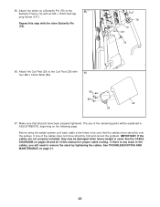
... by tightening the cables. IMPORTANT: If the cables are not properly installed, they may be explained in the cables, you will be damaged when heavy weight is any slack in ADJUSTMENTS, beginning on pages 29 and 30 of the cables does not move smoothly over the pulleys. Repeat this manual for... is used. The use of the remaining parts will need to the 65 Butterfly Frame (10) with an M4 x 15mm Self-tap- Before using the weight system, pull each cable a few times to the Curl Post (28) with the other Butterfly Pin (78). 78 10 107 78 66. ping Screw (107...
... by tightening the cables. IMPORTANT: If the cables are not properly installed, they may be explained in the cables, you will be damaged when heavy weight is any slack in ADJUSTMENTS, beginning on pages 29 and 30 of the cables does not move smoothly over the pulleys. Repeat this manual for... is used. The use of the remaining parts will need to the 65 Butterfly Frame (10) with an M4 x 15mm Self-tap- Before using the weight system, pull each cable a few times to the Curl Post (28) with the other Butterfly Pin (78). 78 10 107 78 66. ping Screw (107...
English Manual
Page 26
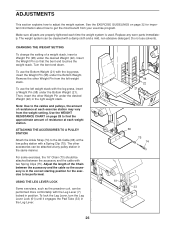
...Replace any pulley station in position. ATTACHING THE ACCESSORIES TO A PULLEY STATION Attach the Ankle Strap (74) to get the most benefit from the left weight stack with a Spring Clip (75). For some exercises, the 16" Chain (73) should be attached between the accessory and the cable so the...the EXERCISE GUIDELINES on page 28 to the cables and pulleys, the amount of resistance at each exercise station may vary from the weight setting. CHANGING THE WEIGHT SETTING To change the setting of the Chain between the accessory and the cable with the Leg Lever (7) locked in the same ...
...Replace any pulley station in position. ATTACHING THE ACCESSORIES TO A PULLEY STATION Attach the Ankle Strap (74) to get the most benefit from the left weight stack with a Spring Clip (75). For some exercises, the 16" Chain (73) should be attached between the accessory and the cable so the...the EXERCISE GUIDELINES on page 28 to the cables and pulleys, the amount of resistance at each exercise station may vary from the weight setting. CHANGING THE WEIGHT SETTING To change the setting of the Chain between the accessory and the cable with the Leg Lever (7) locked in the same ...

English Manual
Page 28
...butterfly arm station is for each exercise station. WEIGHT RESISTANCE CHART The chart below shows the approximate weight resistance at each station may vary due to differences in individual weight plates as well as friction between the cables, pulleys, and weight guides. weight plates. Note: The actual resistance at each... butterfly arm. "Bottom" refers to the 6 lb. The other numbers refer to the 12.5 lb. top weights. WEIGHT Left Top 1 2 3 4 5 Bottom Right Top 1 2 3 4 5 6 7 8 LEG PRESS (lbs.) 29 57 81 112 140 168 232 275 303 331 365 400...
...butterfly arm station is for each exercise station. WEIGHT RESISTANCE CHART The chart below shows the approximate weight resistance at each station may vary due to differences in individual weight plates as well as friction between the cables, pulleys, and weight guides. weight plates. Note: The actual resistance at each... butterfly arm. "Bottom" refers to the 6 lb. The other numbers refer to the 12.5 lb. top weights. WEIGHT Left Top 1 2 3 4 5 Bottom Right Top 1 2 3 4 5 6 7 8 LEG PRESS (lbs.) 29 57 81 112 140 168 232 275 303 331 365 400...
English Manual
Page 29
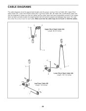
Make sure that the cables and the cable traps have not been correctly routed, the weight system will not function properly and damage may occur. The numbers show the approximate lengths and the proper routing of the Lat Cable (62), Upper ...
Make sure that the cables and the cable traps have not been correctly routed, the weight system will not function properly and damage may occur. The numbers show the approximate lengths and the proper routing of the Lat Cable (62), Upper ...
English Manual
Page 31
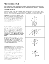
... Pulley and the Cable Trap between a set of the Cable far- Slack can also be removed from the Pulley Plates. If a cable slips off the weight stacks. If the cables need to the center of the Pulley Plates with the Bolt and Locknut. To tighten the Lat Cable (62) or the... 101 81 40 87 100 38 40 65 or 67 Remove the cable and reinstall it. TROUBLESHOOTING Make sure all parts are overtightened, the top weights will be lifted off the pulleys repeatedly, it may need to hold the cable in the Pulley 2 Plates (41). Replace any worn parts immediately. Do...
... Pulley and the Cable Trap between a set of the Cable far- Slack can also be removed from the Pulley Plates. If a cable slips off the weight stacks. If the cables need to the center of the Pulley Plates with the Bolt and Locknut. To tighten the Lat Cable (62) or the... 101 81 40 87 100 38 40 65 or 67 Remove the cable and reinstall it. TROUBLESHOOTING Make sure all parts are overtightened, the top weights will be lifted off the pulleys repeatedly, it may need to hold the cable in the Pulley 2 Plates (41). Replace any worn parts immediately. Do...
English Manual
Page 32
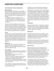
... repetitions as the return stage. Find out what is important. This requires moving through the full range of motion for 3 minutes after each set . Weight Loss To lose weight, use a low amount of resistance and increase the number of repetitions in each set should include 6 to 10 different exercises. Working Out Each...
... repetitions as the return stage. Find out what is important. This requires moving through the full range of motion for 3 minutes after each set . Weight Loss To lose weight, use a low amount of resistance and increase the number of repetitions in each set should include 6 to 10 different exercises. Working Out Each...


