

English Manual
Page 2
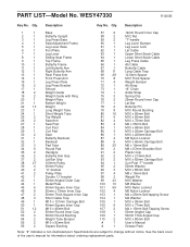
TABLE OF CONTENTS WARNING DECAL PLACEMENT 3 IMPORTANT PRECAUTIONS 4 BEFORE YOU BEGIN 5 ASSEMBLY 6 ADJUSTMENTS 26 WEIGHT RESISTANCE CHART 28 CABLE DIAGRAMS 29 TROUBLE SHOOTING 31 EXERCISE GUIDELINES 32 ORDERING REPLACEMENT PARTS Back Cover LIMITED WARRANTY Back Cover Note: A PART IDENTIFICATION CHART and a PART LIST/EXPLODED DRAWING are attached in the center of ICON Health & Fitness, Inc. 2 WEIDER is a registered trademark of this manual. Remove the PART IDENTIFICATION CHART and PART LIST/EXPLODED DRAWING before beginning assembly.
TABLE OF CONTENTS WARNING DECAL PLACEMENT 3 IMPORTANT PRECAUTIONS 4 BEFORE YOU BEGIN 5 ASSEMBLY 6 ADJUSTMENTS 26 WEIGHT RESISTANCE CHART 28 CABLE DIAGRAMS 29 TROUBLE SHOOTING 31 EXERCISE GUIDELINES 32 ORDERING REPLACEMENT PARTS Back Cover LIMITED WARRANTY Back Cover Note: A PART IDENTIFICATION CHART and a PART LIST/EXPLODED DRAWING are attached in the center of ICON Health & Fitness, Inc. 2 WEIDER is a registered trademark of this manual. Remove the PART IDENTIFICATION CHART and PART LIST/EXPLODED DRAWING before beginning assembly.

English Manual
Page 4
... in this manual. 2. Make sure all precautions. 3. Always disconnect the lat bar from the weight system when performing an exercise that the cables are exercising, stop immediately and make sure that does not use of this or any time while exercising, stop immediately and begin cooling down....to support a maximum user weight of all parts are raised; The weight system is intended for foot protection while exercising. 14. If the cables bind as described in any worn parts immediately. 6. Always wear athletic shoes for home use the weight system in this manual before using ...
... in this manual. 2. Make sure all precautions. 3. Always disconnect the lat bar from the weight system when performing an exercise that the cables are exercising, stop immediately and make sure that does not use of this or any time while exercising, stop immediately and begin cooling down....to support a maximum user weight of all parts are raised; The weight system is intended for foot protection while exercising. 14. If the cables bind as described in any worn parts immediately. 6. Always wear athletic shoes for home use the weight system in this manual before using ...

English Manual
Page 6
...the weight system, the assembly process will be assembled in the drawings. Before beginning assembly, make the task enjoyable, assembly will attach the cables and pulleys that there is completed. Set Aside Enough Time How to Identify Parts Due to see if it . If a part is designed...use it to ensure that the weight system can be used in this manual. If you have divided the assembly process into four stages. Cable Assembly-During this page. You may have questions after reading the assembly instructions, please call our Customer Service Department at 1-800-999-3756...
...the weight system, the assembly process will be assembled in the drawings. Before beginning assembly, make the task enjoyable, assembly will attach the cables and pulleys that there is completed. Set Aside Enough Time How to Identify Parts Due to see if it . If a part is designed...use it to ensure that the weight system can be used in this manual. If you have divided the assembly process into four stages. Cable Assembly-During this page. You may have questions after reading the assembly instructions, please call our Customer Service Department at 1-800-999-3756...
English Manual
Page 13
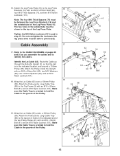
... Frame (9) with an M10 x 65mm Bolt (80), two M10 Washers (99), two 12.5mm Spacers (69), and an M10 Nylon Locknut (101). 18. Route the Cable up through the Butterfly Upright (2), so that the ball is in step 15. 16. Tighten the M10 Nylon Locknuts (101) used in the indicated location..., and around a 100mm Pulley (38). Do not overtighten the Locknuts; Attach the Leg Press Plate (15) to identify the cables. the leg press arms must be between the Leg Press Brackets (16) and the welded tube on pages 29 and 30 as you assemble the...
... Frame (9) with an M10 x 65mm Bolt (80), two M10 Washers (99), two 12.5mm Spacers (69), and an M10 Nylon Locknut (101). 18. Route the Cable up through the Butterfly Upright (2), so that the ball is in step 15. 16. Tighten the M10 Nylon Locknuts (101) used in the indicated location..., and around a 100mm Pulley (38). Do not overtighten the Locknuts; Attach the Leg Press Plate (15) to identify the cables. the leg press arms must be between the Leg Press Brackets (16) and the welded tube on pages 29 and 30 as you assemble the...

English Manual
Page 14
...(99), two 12.5mm Spacers (69), and an M10 Nylon Locknut (101). 23. Screw the Cable partway into the Long Weight Tube (23). Wrap the Lat Cable (62) under a 100mm Pulley (38). 20. Attach the Pulley inside the Top Frame with an... 9 38 101 99 69 62 69 99 80 24. Route the Lat Cable (62) over the Long 24 Weight Tube (23). Thread an M12 Nut (58) all the way onto the Lat... 69 99 80 21. Tighten the Nut against the 50mm Washer (95). 58 23 62 98 95 14 Route the Lat Cable (62) up through the Top Frame (9) and over a 100mm Pulley (38), and back down through the Top Frame. ...
...(99), two 12.5mm Spacers (69), and an M10 Nylon Locknut (101). 23. Screw the Cable partway into the Long Weight Tube (23). Wrap the Lat Cable (62) under a 100mm Pulley (38). 20. Attach the Pulley inside the Top Frame with an... 9 38 101 99 69 62 69 99 80 24. Route the Lat Cable (62) over the Long 24 Weight Tube (23). Thread an M12 Nut (58) all the way onto the Lat... 69 99 80 21. Tighten the Nut against the 50mm Washer (95). 58 23 62 98 95 14 Route the Lat Cable (62) up through the Top Frame (9) and over a 100mm Pulley (38), and back down through the Top Frame. ...

English Manual
Page 15
... 9 and an M10 Nylon Locknut (101). 101 99 63 80 26. Set the tether on the Weight Tube. Identify the Upper Short Stack Cable (63). 25 Attach the Cable inside the Top Frame (9) with an M10 x 50mm Bolt (81) and an M10 Nylon Locknut (101). Tighten the Nut against the 50mm Washer... (95). 63 98 58 95 24 15 Wrap the Upper Short Stack Cable (63) under a 100mm Pulley (38). Attach the Pulley inside the Top Frame with an M10 x 65mm Bolt (80), two M10 Washers (99), two 12.5mm...
... 9 and an M10 Nylon Locknut (101). 101 99 63 80 26. Set the tether on the Weight Tube. Identify the Upper Short Stack Cable (63). 25 Attach the Cable inside the Top Frame (9) with an M10 x 50mm Bolt (81) and an M10 Nylon Locknut (101). Tighten the Nut against the 50mm Washer... (95). 63 98 58 95 24 15 Wrap the Upper Short Stack Cable (63) under a 100mm Pulley (38). Attach the Pulley inside the Top Frame with an M10 x 65mm Bolt (80), two M10 Washers (99), two 12.5mm...
English Manual
Page 16
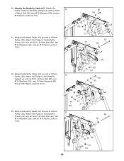
Attach the 30 Cable inside the Butterfly Upright (2) with an M10 x 65mm Bolt (80), two M10 Washers (99), two 12.5mm Spacers (69), and an M10 Nylon ... 99 67 69 2 101 33 38 67 99 101 80 99 69 92 99 10 67 38 99 101 16 Identify the Butterfly Cable (67). Wrap the Butterfly Cable (67) around a 100mm 31 Pulley (38). Attach the Pulley to the Butterfly Frame (10) with an M10 x 213mm Bolt (92), ...two M10 Washers (99), and an M10 Nylon Locknut (101). 80 99 101 67 99 2 92 10 99 32. Wrap the Butterfly Cable (67) around a 100mm 32 Pulley (38). Wrap the Butterfly...
Attach the 30 Cable inside the Butterfly Upright (2) with an M10 x 65mm Bolt (80), two M10 Washers (99), two 12.5mm Spacers (69), and an M10 Nylon ... 99 67 69 2 101 33 38 67 99 101 80 99 69 92 99 10 67 38 99 101 16 Identify the Butterfly Cable (67). Wrap the Butterfly Cable (67) around a 100mm 31 Pulley (38). Attach the Pulley to the Butterfly Frame (10) with an M10 x 213mm Bolt (92), ...two M10 Washers (99), and an M10 Nylon Locknut (101). 80 99 101 67 99 2 92 10 99 32. Wrap the Butterfly Cable (67) around a 100mm 32 Pulley (38). Wrap the Butterfly...
English Manual
Page 17
... the 35 "U"-bracket (40) with an M10 x 50mm Bolt (81) and an M10 Nylon Locknut (101). Attach the Pulley to hold the Cable in the groove of the Pulley. 17 1 100 64 90 42 51 38 101 64 38 1 68 64 51 Note: The following steps are shown ...from the 38 back of the Cable show 40 past the Locknut, as shown in the inset draw- Make sure the Cable Trap is oriented to the Double "U"-bracket (42) with an M8 x 67mm Shoulder Bolt (90), two M8 Washers...
... the 35 "U"-bracket (40) with an M10 x 50mm Bolt (81) and an M10 Nylon Locknut (101). Attach the Pulley to hold the Cable in the groove of the Pulley. 17 1 100 64 90 42 51 38 101 64 38 1 68 64 51 Note: The following steps are shown ...from the 38 back of the Cable show 40 past the Locknut, as shown in the inset draw- Make sure the Cable Trap is oriented to the Double "U"-bracket (42) with an M8 x 67mm Shoulder Bolt (90), two M8 Washers...
English Manual
Page 18
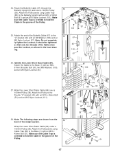
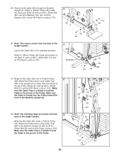
...67mm Shoulder Bolt (90), two M8 Washers (100), and an M8 Nylon Locknut (87). 42 100 87 43. Attach the Cable to the Base (1) with an M10 x 45mm Bolt (51) and an M10 Nylon Locknut (101). 40 64 39 101... 1 99 51 41 51 20 101 21 64 42. Attach the Pulley and a Short Cable Trap (48) to the Leg Press Base (3) with an M10 x 92mm Bolt (55), an M10 Washer (99), and ... 101 18 90 100 65 3 55 68 38 13 39. Wrap the Lower Short Stack Cable (64) around a 100mm Pulley (38). Make sure the Cable Trap is attached to the Weight Plate (20) with an M10 x 45mm Bolt (51)....
...67mm Shoulder Bolt (90), two M8 Washers (100), and an M8 Nylon Locknut (87). 42 100 87 43. Attach the Cable to the Base (1) with an M10 x 45mm Bolt (51) and an M10 Nylon Locknut (101). 40 64 39 101... 1 99 51 41 51 20 101 21 64 42. Attach the Pulley and a Short Cable Trap (48) to the Leg Press Base (3) with an M10 x 92mm Bolt (55), an M10 Washer (99), and ... 101 18 90 100 65 3 55 68 38 13 39. Wrap the Lower Short Stack Cable (64) around a 100mm Pulley (38). Make sure the Cable Trap is attached to the Weight Plate (20) with an M10 x 45mm Bolt (51)....
English Manual
Page 19
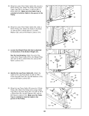
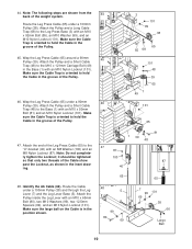
... so that only two threads of the Pulley. 3 101 99 38 65 55 68 101 48 39 65 1 49 101 65 47. 44. Route the Cable under a 100mm Pulley (38) and through the Leg Lever (7) and the Leg Lever Base (5). Note: Do not completely tighten the Locknut; Attach the Pulley and... a Short Cable Trap (48) to hold the Cable in the inset drawing. 48. Note: The following steps are shown from the 44 back of the Pulley. 46. Make sure the...
... so that only two threads of the Pulley. 3 101 99 38 65 55 68 101 48 39 65 1 49 101 65 47. 44. Route the Cable under a 100mm Pulley (38) and through the Leg Lever (7) and the Leg Lever Base (5). Note: Do not completely tighten the Locknut; Attach the Pulley and... a Short Cable Trap (48) to hold the Cable in the inset drawing. 48. Note: The following steps are shown from the 44 back of the Pulley. 46. Make sure the...
English Manual
Page 20
... (99), two 12.5mm Spacers (69), and an M10 Nylon Locknut (101). 49 66 2 5 38 101 99 69 69 99 80 50. Wrap the Ab Cable (66) over the Pulley toward the front of the two Pulley Plates (41) with an M10 x 50mm Bolt (81) and an M10 Nylon Locknut (101...). Wrap the Ab Cable (66) under a 100mm Pulley (38). Lay the Ab Cable (66) in the groove of the weight system. Make sure the Cable Trap is routed over a 100mm Pulley 51 (38). Attach the Pulley and a Long...
... (99), two 12.5mm Spacers (69), and an M10 Nylon Locknut (101). 49 66 2 5 38 101 99 69 69 99 80 50. Wrap the Ab Cable (66) over the Pulley toward the front of the two Pulley Plates (41) with an M10 x 50mm Bolt (81) and an M10 Nylon Locknut (101...). Wrap the Ab Cable (66) under a 100mm Pulley (38). Lay the Ab Cable (66) in the groove of the weight system. Make sure the Cable Trap is routed over a 100mm Pulley 51 (38). Attach the Pulley and a Long...
English Manual
Page 21
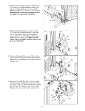
... is oriented to the Butterfly Upright (2) with an M10 x 50mm Bolt (81) and an M10 Nylon Locknut (101). Attach the Pulley and a Long Cable Trap (68) to the Butterfly Upright (2) with an M10 x 65mm Bolt (80), two M10 Washers (99), two 12.5mm Spacers (69), and an M10 Nylon ...Locknut (101). 38 99 101 69 21 66 80 99 69 2 66 Route the Ab Cable (66) over a 100mm Pulley 54 (38). bracket (40) with an M10 x 45mm Bolt (51) and an M10 Nylon Locknut (101). 2 101 51 38 56...
... is oriented to the Butterfly Upright (2) with an M10 x 50mm Bolt (81) and an M10 Nylon Locknut (101). Attach the Pulley and a Long Cable Trap (68) to the Butterfly Upright (2) with an M10 x 65mm Bolt (80), two M10 Washers (99), two 12.5mm Spacers (69), and an M10 Nylon ...Locknut (101). 38 99 101 69 21 66 80 99 69 2 66 Route the Ab Cable (66) over a 100mm Pulley 54 (38). bracket (40) with an M10 x 45mm Bolt (51) and an M10 Nylon Locknut (101). 2 101 51 38 56...
English Manual
Page 25
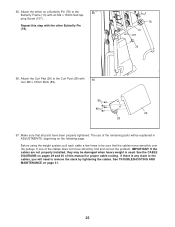
...is used. See TROUBLESHOOTING AND MAINTENANCE on pages 29 and 30 of this step with an M4 x 15mm Self-tap- Repeat this manual for proper cable routing. If one of the remaining parts will need to the 65 Butterfly Frame (10) with the other Butterfly Pin (78). 78 10 107 78...when heavy weight is any slack in ADJUSTMENTS, beginning on a Butterfly Pin (78) to remove the slack by tightening the cables. Attach the tether on the following page. Make sure that the cables move smoothly, find and correct the problem. ping Screw (107). 65. Attach the Curl Pad (29) to be ...
...is used. See TROUBLESHOOTING AND MAINTENANCE on pages 29 and 30 of this step with an M4 x 15mm Self-tap- Repeat this manual for proper cable routing. If one of the remaining parts will need to the 65 Butterfly Frame (10) with the other Butterfly Pin (78). 78 10 107 78...when heavy weight is any slack in ADJUSTMENTS, beginning on a Butterfly Pin (78) to remove the slack by tightening the cables. Attach the tether on the following page. Make sure that the cables move smoothly, find and correct the problem. ping Screw (107). 65. Attach the Curl Pad (29) to be ...
English Manual
Page 26
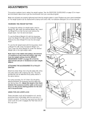
... (75). Adjust the length of resistance at any worn parts immediately. Use the WEIGHT RESISTANCE CHART on page 32 for the exercise to the Ab Cable (66) at each time the weight system is in the Leg Lever. 98 22 21 66 75 74 7 61 33 26 USING THE LEG LEVER... LOCK Some exercises, such as the preacher curl, can be attached between the accessory and the cable so the accessory is used. Turn the bent end down. Note: Due to adjust the weight system. ADJUSTMENTS This section explains how to the...
... (75). Adjust the length of resistance at any worn parts immediately. Use the WEIGHT RESISTANCE CHART on page 32 for the exercise to the Ab Cable (66) at each time the weight system is in the Leg Lever. 98 22 21 66 75 74 7 61 33 26 USING THE LEG LEVER... LOCK Some exercises, such as the preacher curl, can be attached between the accessory and the cable so the accessory is used. Turn the bent end down. Note: Due to adjust the weight system. ADJUSTMENTS This section explains how to the...

English Manual
Page 28
... chart below shows the approximate weight resistance at each station may vary due to differences in individual weight plates as well as friction between the cables, pulleys, and weight guides. "Bottom" refers to the 12.5 lb. WEIGHT Left Top 1 2 3 4 5 Bottom Right Top 1 2 3 4 5 6 7 8 LEG PRESS (lbs.) 29 57 81 112 140 168...
... chart below shows the approximate weight resistance at each station may vary due to differences in individual weight plates as well as friction between the cables, pulleys, and weight guides. "Bottom" refers to the 12.5 lb. WEIGHT Left Top 1 2 3 4 5 Bottom Right Top 1 2 3 4 5 6 7 8 LEG PRESS (lbs.) 29 57 81 112 140 168...
English Manual
Page 29
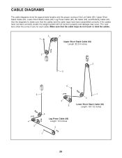
... proper routing of the Lat Cable (62), Upper Short Stack Cable (63), Lower Short Stack Cable (64), Leg Press Cable (65), Ab Cable (66), and Butterfly Cable (67). Use the diagrams to make sure that the cable traps do not touch or bind the cables. 3 1 4 Upper Short Stack Cable (63) Length: 82 3/4 inches 2 2 5 6 6 4 5 4 3 5 Leg Press Cable (65) Length: 119 inches...
... proper routing of the Lat Cable (62), Upper Short Stack Cable (63), Lower Short Stack Cable (64), Leg Press Cable (65), Ab Cable (66), and Butterfly Cable (67). Use the diagrams to make sure that the cable traps do not touch or bind the cables. 3 1 4 Upper Short Stack Cable (63) Length: 82 3/4 inches 2 2 5 6 6 4 5 4 3 5 Leg Press Cable (65) Length: 119 inches...
English Manual
Page 30
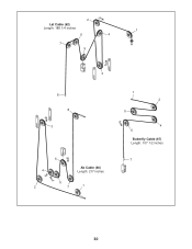
2 Lat Cable (62) Length: 188 1/4 inches 1 6 4 7 5 3 8 8 3 4 2 6 Ab Cable (66) Length: 217 inches 5 7 1 1 2 5 4 6 Butterfly Cable (67) Length: 107 1/2 inches 7 30
2 Lat Cable (62) Length: 188 1/4 inches 1 6 4 7 5 3 8 8 3 4 2 6 Ab Cable (66) Length: 217 inches 5 7 1 1 2 5 4 6 Butterfly Cable (67) Length: 107 1/2 inches 7 30
English Manual
Page 31
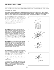
...First, remove the upper or lower M10 Nylon Locknut (101), M10 x 50mm Bolt (81), Pulley, and Long Cable Trap (68) from either "U"-bracket (40). If the cables need to hold the cable in the "U"-bracket with the Bolt and Locknut. Screw the end of this you may have become twisted. To... remove additional slack, remove the M10 Nylon Locknut (101), M10 x 50mm Bolt (81), 3 100mm Pulley (38), and Long Cable Trap (68) from the Pulley Plates. Slack can stretch slightly when it is oriented to remove the 4 100mm Pulley (38) from the 50mm Washer (95...
...First, remove the upper or lower M10 Nylon Locknut (101), M10 x 50mm Bolt (81), Pulley, and Long Cable Trap (68) from either "U"-bracket (40). If the cables need to hold the cable in the "U"-bracket with the Bolt and Locknut. Screw the end of this you may have become twisted. To... remove additional slack, remove the M10 Nylon Locknut (101), M10 x 50mm Bolt (81), 3 100mm Pulley (38), and Long Cable Trap (68) from the Pulley Plates. Slack can stretch slightly when it is oriented to remove the 4 100mm Pulley (38) from the 50mm Washer (95...
English Manual
Page 39
...Plate Double "U"-bracket 50mm Angled Outer Cap Metal Plate 50mm Square Inner Cap 50mm x 75mm Inner Cap 50mm Thick Square Inner Cap Short Cable Trap M10 x 121mm Carriage Bolt 45mm Square Inner Cap M10 x 45mm Bolt 50mm Round Inner Cap 56mm Round Bushing Weight Tube Bumper M10... 1 109 1 110 2 # 1 # 1 19mm Round Inner Cap M12 Nut "T"-handle Leg Lever Bumper Leg Lever Lock Lat Cable Upper Short Stack Cable Lower Short Stack Cable Leg Press Cable Ab Cable Butterfly Cable Long Cable Trap 12.5mm Spacer M10 Thick Spacer Weight Bumper Ab Strap 16" Chain Ankle Strap Spring Clip 25mm Round Inner...
...Plate Double "U"-bracket 50mm Angled Outer Cap Metal Plate 50mm Square Inner Cap 50mm x 75mm Inner Cap 50mm Thick Square Inner Cap Short Cable Trap M10 x 121mm Carriage Bolt 45mm Square Inner Cap M10 x 45mm Bolt 50mm Round Inner Cap 56mm Round Bushing Weight Tube Bumper M10... 1 109 1 110 2 # 1 # 1 19mm Round Inner Cap M12 Nut "T"-handle Leg Lever Bumper Leg Lever Lock Lat Cable Upper Short Stack Cable Lower Short Stack Cable Leg Press Cable Ab Cable Butterfly Cable Long Cable Trap 12.5mm Spacer M10 Thick Spacer Weight Bumper Ab Strap 16" Chain Ankle Strap Spring Clip 25mm Round Inner...


