

English Manual
Page 1
If you have questions, or if there are missing or damaged parts, we are committed to providing complete customer satisfaction. TO AVOID DELAYS, PLEASE CALL DIRECT TO OUR TOLLFREE CUSTOMER HOT LINE. Save this equipment. Write the serial number in this manual before using this manual for future reference. The trained technicians on our customer hot line will guarantee complete satisfaction through direct assistance from our factory. CUSTOMER HOT LINE: 1-800-999-3756 Mon.-Fri., 6 a.m.-6 p.m. Patent Pending Visit our website at www.weiderfitness.com new products, prizes, fitness ...
If you have questions, or if there are missing or damaged parts, we are committed to providing complete customer satisfaction. TO AVOID DELAYS, PLEASE CALL DIRECT TO OUR TOLLFREE CUSTOMER HOT LINE. Save this equipment. Write the serial number in this manual before using this manual for future reference. The trained technicians on our customer hot line will guarantee complete satisfaction through direct assistance from our factory. CUSTOMER HOT LINE: 1-800-999-3756 Mon.-Fri., 6 a.m.-6 p.m. Patent Pending Visit our website at www.weiderfitness.com new products, prizes, fitness ...

English Manual
Page 2
Remove the PART IDENTIFICATION CHART and PART LIST/EXPLODED DRAWING before beginning assembly. TABLE OF CONTENTS WARNING DECAL PLACEMENT 3 IMPORTANT PRECAUTIONS 4 BEFORE YOU BEGIN 5 ASSEMBLY 6 ADJUSTMENTS 26 WEIGHT RESISTANCE CHART 28 CABLE DIAGRAMS 29 TROUBLE SHOOTING 31 EXERCISE GUIDELINES 32 ORDERING REPLACEMENT PARTS Back Cover LIMITED WARRANTY Back Cover Note: A PART IDENTIFICATION CHART and a PART LIST/EXPLODED DRAWING are attached in the center of ICON Health & Fitness, Inc. 2 WEIDER is a registered trademark of this manual.
Remove the PART IDENTIFICATION CHART and PART LIST/EXPLODED DRAWING before beginning assembly. TABLE OF CONTENTS WARNING DECAL PLACEMENT 3 IMPORTANT PRECAUTIONS 4 BEFORE YOU BEGIN 5 ASSEMBLY 6 ADJUSTMENTS 26 WEIGHT RESISTANCE CHART 28 CABLE DIAGRAMS 29 TROUBLE SHOOTING 31 EXERCISE GUIDELINES 32 ORDERING REPLACEMENT PARTS Back Cover LIMITED WARRANTY Back Cover Note: A PART IDENTIFICATION CHART and a PART LIST/EXPLODED DRAWING are attached in the center of ICON Health & Fitness, Inc. 2 WEIDER is a registered trademark of this manual.

English Manual
Page 3
Decal 3 3 WARNING DECAL PLACEMENT The decals shown here have been placed on the weight system. If a decal is missing or illegible, please call our Customer Service Department toll-free at 1-800-999-3756, Monday through Friday, 6 a.m. Decal 2 Decal 3 Decal 1 Decal 2 Decal 3 Decal 1 Keep hands and fingers clear of this area. Apply the decal in the location shown. Mountain Time, to order a free replacement decal. Decal 2 • Keep clear of this area. until 6 p.m.
Decal 3 3 WARNING DECAL PLACEMENT The decals shown here have been placed on the weight system. If a decal is missing or illegible, please call our Customer Service Department toll-free at 1-800-999-3756, Monday through Friday, 6 a.m. Decal 2 Decal 3 Decal 1 Decal 2 Decal 3 Decal 1 Keep hands and fingers clear of this area. Apply the decal in the location shown. Mountain Time, to order a free replacement decal. Decal 2 • Keep clear of this area. until 6 p.m.

English Manual
Page 4
Read all instructions in this manual before using the weight system. Use the weight system only as you feel pain or dizziness at all instructions before using the weight system. 1. Cover the floor beneath the weight system to support a maximum user weight of 300 pounds. The weight system is especially important for home use of this or any worn parts immediately. 6. the weights will fall with pre-existing health problems. Read all times. If the cables bind as described in this manual. 2. Always disconnect the lat bar from moving parts. 8. This is ...
Read all instructions in this manual before using the weight system. Use the weight system only as you feel pain or dizziness at all instructions before using the weight system. 1. Cover the floor beneath the weight system to support a maximum user weight of 300 pounds. The weight system is especially important for home use of this or any worn parts immediately. 6. the weights will fall with pre-existing health problems. Read all times. If the cables bind as described in this manual. 2. Always disconnect the lat bar from moving parts. 8. This is ...

English Manual
Page 5
... on a decal attached to tone your body, build dramatic muscle size and strength, or improve your goal is WESY47330. If you for selecting the versatile WEIDER® CLUB C4800 weight system. Mountain Time (excluding holidays). Length: 60 in. tions, please call our Customer Service Department tollfree at 1-800-999-3756, Monday through Friday...
... on a decal attached to tone your body, build dramatic muscle size and strength, or improve your goal is WESY47330. If you for selecting the versatile WEIDER® CLUB C4800 weight system. Mountain Time (excluding holidays). Length: 60 in. tions, please call our Customer Service Department tollfree at 1-800-999-3756, Monday through Friday...

English Manual
Page 6
ASSEMBLY Make Assembly Easier for Yourself Everything in this manual is enough room to walk around the weight system as you assemble it. This brief introduction will assemble the arms and the leg lever. Make sure that there is designed to Unpack the Box Tightening Parts To make sure that the weight system can be assembled successfully by anyone. How to ensure that all parts are found in individual bags. If you begin by deciding to make sure to the many features of the weight system. Cable Assembly-During this stage you will save you much more convenient if you ...
ASSEMBLY Make Assembly Easier for Yourself Everything in this manual is enough room to walk around the weight system as you assemble it. This brief introduction will assemble the arms and the leg lever. Make sure that there is designed to Unpack the Box Tightening Parts To make sure that the weight system can be assembled successfully by anyone. How to ensure that all parts are found in individual bags. If you begin by deciding to make sure to the many features of the weight system. Cable Assembly-During this stage you will save you much more convenient if you ...

English Manual
Page 7
Refer to the PART IDENTIFICATION CHART in the box on the indicated M10 x 92mm Carriage Bolts (85) and thread two M10 Nylon Locknuts (101) onto the Bolts. Insert three M10 x 92mm Carriage Bolts (85) and an M10 x 121mm Carriage Bolt (49) up into the Butterfly Upright (2). Slide the Butterfly Upright (2) on page 6. Do not tighten the Locknuts yet. 46 101 49 85 2 46 46 46 1 85 3 46 46 2 45 101 85 7 Press two 50mm x 75mm Inner Caps (46) and a 50mm Square Inner Cap (45) into the Base (1). Press four 50mm x 75mm Inner Caps (46) into the Base (1) and the Leg Press Base (3). ...
Refer to the PART IDENTIFICATION CHART in the box on the indicated M10 x 92mm Carriage Bolts (85) and thread two M10 Nylon Locknuts (101) onto the Bolts. Insert three M10 x 92mm Carriage Bolts (85) and an M10 x 121mm Carriage Bolt (49) up into the Butterfly Upright (2). Slide the Butterfly Upright (2) on page 6. Do not tighten the Locknuts yet. 46 101 49 85 2 46 46 46 1 85 3 46 46 2 45 101 85 7 Press two 50mm x 75mm Inner Caps (46) and a 50mm Square Inner Cap (45) into the Base (1). Press four 50mm x 75mm Inner Caps (46) into the Base (1) and the Leg Press Base (3). ...
English Manual
Page 8
Do not tighten the Locknuts yet. 99 101 82 101 46 101 4. Insert the two Weight Guides with Rings (19) into the indicated holes in the Base (1). Attach the Weight Guides to the Butterfly Upright (2) with two M10 x 65mm Bolts (80), four M10 Washers (99), four 12.5mm Spacers (69), and two M10 Nylon Locknuts (101). 46 88 6 19 18 101 99 69 99 1 69 99 69 99 80 8 Attach the Leg Lever Base (5) to the Base with two M10 x 75mm Bolts (82), an M10 x 95mm Bolt (105), an M10 Washer (99), and three M10 Nylon Locknuts (101). Do not tighten the Locknuts yet. 2 47 101 5 ...
Do not tighten the Locknuts yet. 99 101 82 101 46 101 4. Insert the two Weight Guides with Rings (19) into the indicated holes in the Base (1). Attach the Weight Guides to the Butterfly Upright (2) with two M10 x 65mm Bolts (80), four M10 Washers (99), four 12.5mm Spacers (69), and two M10 Nylon Locknuts (101). 46 88 6 19 18 101 99 69 99 1 69 99 69 99 80 8 Attach the Leg Lever Base (5) to the Base with two M10 x 75mm Bolts (82), an M10 x 95mm Bolt (105), an M10 Washer (99), and three M10 Nylon Locknuts (101). Do not tighten the Locknuts yet. 2 47 101 5 ...

English Manual
Page 9
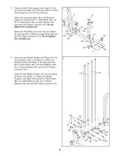
Insert the Long Weight Tube into the Short Weight Tube (24). Make sure the Weight is oriented with the pin groove on the Long Weight Tube (23) rests in the grooves in the bottom of the Top Weight. 18 Pin Groove 25 Lubricate Pin 23 54 22 71 6. Slide the Bottom Weight (21) onto the Weight Guides with Rings (19). Make sure the Weights are oriented with the pin grooves on the Short Weight Tube (24) rests in the grooves in the bottom of the Top Weight. 25 Lubricate Pin 24 54 22 Pin Groove 21 Pin Groove 71 19 9 Make sure the Weights are oriented with the pin grooves ...
Insert the Long Weight Tube into the Short Weight Tube (24). Make sure the Weight is oriented with the pin groove on the Long Weight Tube (23) rests in the grooves in the bottom of the Top Weight. 18 Pin Groove 25 Lubricate Pin 23 54 22 71 6. Slide the Bottom Weight (21) onto the Weight Guides with Rings (19). Make sure the Weights are oriented with the pin grooves on the Short Weight Tube (24) rests in the grooves in the bottom of the Top Weight. 25 Lubricate Pin 24 54 22 Pin Groove 21 Pin Groove 71 19 9 Make sure the Weights are oriented with the pin grooves ...
English Manual
Page 10
Do not tighten the Locknuts yet. Do not tighten the Locknuts yet. 46 8. Tighten the M10 Nylon Locknuts (101) used in the Seat Adjustment Frame. Press a 50mm x 75mm Inner Cap (46) into the indicated end of the Weight Guides (18, 19). Press a 50mm Square Inner Cap (45) into the Top Frame (9). 7 Slide the welded tubes on the Top Frame (9) over the upper ends of the Seat Adjustment Frame (4). Press the Metal Plate (44) and the 50mm Angled Outer Cap (43) onto the other end of the adjustment holes in steps 1-3 and 7-9. 9 101 88 101 4 101 3 88 101 10 Turn the ...
Do not tighten the Locknuts yet. Do not tighten the Locknuts yet. 46 8. Tighten the M10 Nylon Locknuts (101) used in the Seat Adjustment Frame. Press a 50mm x 75mm Inner Cap (46) into the indicated end of the Weight Guides (18, 19). Press a 50mm Square Inner Cap (45) into the Top Frame (9). 7 Slide the welded tubes on the Top Frame (9) over the upper ends of the Seat Adjustment Frame (4). Press the Metal Plate (44) and the 50mm Angled Outer Cap (43) onto the other end of the adjustment holes in steps 1-3 and 7-9. 9 101 88 101 4 101 3 88 101 10 Turn the ...
English Manual
Page 11
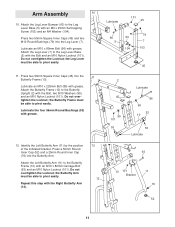
Attach the Leg Lever Bumper (60) to the Butterfly Upright (2) with an M4 x 25mm Self-tapping Screw (103) and an M4 Washer (104). Lubricate an M10 x 85mm Bolt (96) with grease. Press two 50mm Square Inner Caps (45) into the Leg Lever (7). Do not overtighten the Locknut; Lubricate an M10 x 225mm Bolt (86) with grease. Attach the Butterfly Frame (10) to the Leg Lever Base (5) with the Bolt, two M10 Washers (99), and an M10 Nylon Locknut (101). Lubricate 101 45 96 60 5 104 79 7 103 45 2 45 99 101 53 Lubricate 86 99 53 10 53 Lubricate 12. Press two 50mm Square ...
Attach the Leg Lever Bumper (60) to the Butterfly Upright (2) with an M4 x 25mm Self-tapping Screw (103) and an M4 Washer (104). Lubricate an M10 x 85mm Bolt (96) with grease. Press two 50mm Square Inner Caps (45) into the Leg Lever (7). Do not overtighten the Locknut; Lubricate an M10 x 225mm Bolt (86) with grease. Attach the Butterfly Frame (10) to the Leg Lever Base (5) with the Bolt, two M10 Washers (99), and an M10 Nylon Locknut (101). Lubricate 101 45 96 60 5 104 79 7 103 45 2 45 99 101 53 Lubricate 86 99 53 10 53 Lubricate 12. Press two 50mm Square ...

English Manual
Page 12
Attach the Rear Press Arm (13), which has a hole in the lower area, to the Leg Press Base (3) with the other Seat Arm (26). 26 102 8 14. Attach the Front Press Arm (14) to pivot easily. Repeat with the Bolt and an M10 Nylon Locknut (101). Lubricate an M10 x 77mm Bolt (106) with the Bolts and two M10 Nylon Locknuts (101). the Press Arm must be able to the Leg Press Base (3) in the location shown. 109 108 14 Hole 106 Lubricate 13 110 16 14 101 16 Warning Decal 12 Attach the two Leg Press Brackets (16) to the Sliding Seat Frame 13 (8) with 15 grease. Make sure the...
Attach the Rear Press Arm (13), which has a hole in the lower area, to the Leg Press Base (3) with the other Seat Arm (26). 26 102 8 14. Attach the Front Press Arm (14) to pivot easily. Repeat with the Bolt and an M10 Nylon Locknut (101). Lubricate an M10 x 77mm Bolt (106) with the Bolts and two M10 Nylon Locknuts (101). the Press Arm must be able to the Leg Press Base (3) in the location shown. 109 108 14 Hole 106 Lubricate 13 110 16 14 101 16 Warning Decal 12 Attach the two Leg Press Brackets (16) to the Sliding Seat Frame 13 (8) with 15 grease. Make sure the...
English Manual
Page 13
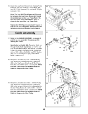
Tighten the M10 Nylon Locknuts (101) used in the indicated location, and around a 100mm Pulley (38). Do not overtighten the Locknuts; The two holes in the groove of the Pulley. 101 62 81 41 41 68 38 13 Cable Assembly 17. Identify the Lat Cable (62). Note: The four M10 Thick Spacers (70) must be able to the Leg Press Brackets (16) with an M10 x 65mm Bolt (80), two M10 Washers (99), two 12.5mm Spacers (69), and an M10 Nylon Locknut (101). 18. Attach the Pulley and a Long Cable Trap (68) to the top of the two Pulley Plates (41) with an M10 x 50mm Bolt (81) and an M10 ...
Tighten the M10 Nylon Locknuts (101) used in the indicated location, and around a 100mm Pulley (38). Do not overtighten the Locknuts; The two holes in the groove of the Pulley. 101 62 81 41 41 68 38 13 Cable Assembly 17. Identify the Lat Cable (62). Note: The four M10 Thick Spacers (70) must be able to the Leg Press Brackets (16) with an M10 x 65mm Bolt (80), two M10 Washers (99), two 12.5mm Spacers (69), and an M10 Nylon Locknut (101). 18. Attach the Pulley and a Long Cable Trap (68) to the top of the two Pulley Plates (41) with an M10 x 50mm Bolt (81) and an M10 ...

English Manual
Page 14
Attach the Pulley inside the Top Frame with an M10 x 65mm Bolt (80), two M10 Washers (99), two 12.5mm Spacers (69), and an M10 Nylon Locknut (101). 23. Tighten the Nut against the 50mm Washer (95). 58 23 62 98 95 14 Set the tether on the Weight Tube. Set a 50mm Washer (95) on a Weight Pin (98) over a 100mm Pulley (38). Thread an M12 Nut (58) all the way onto the Lat Cable (62). Route the Lat Cable (62) up through the Top 20 Frame (9), over a 100mm Pulley (38) and down through the Top Frame. Wrap the Lat Cable (62) under a 100mm Pulley (38). Route the Lat Cable (62) ...
Attach the Pulley inside the Top Frame with an M10 x 65mm Bolt (80), two M10 Washers (99), two 12.5mm Spacers (69), and an M10 Nylon Locknut (101). 23. Tighten the Nut against the 50mm Washer (95). 58 23 62 98 95 14 Set the tether on the Weight Tube. Set a 50mm Washer (95) on a Weight Pin (98) over a 100mm Pulley (38). Thread an M12 Nut (58) all the way onto the Lat Cable (62). Route the Lat Cable (62) up through the Top 20 Frame (9), over a 100mm Pulley (38) and down through the Top Frame. Wrap the Lat Cable (62) under a 100mm Pulley (38). Route the Lat Cable (62) ...

English Manual
Page 15
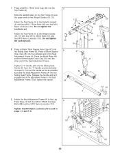
Attach the Pulley and a Long Cable Trap (68) to hold the Cable in a "U"bracket (40) with an M10 x 65mm Bolt (80), two M10 Washers (99), two 12.5mm Spacers (69), and an M10 Nylon Locknut (101). 26 63 68 38 81 101 40 27 63 9 38 101 99 69 69 99 80 28 38 101 99 69 9 63 69 99 80 29. Thread an M12 Nut (58) all the way onto the Upper Short Stack Cable (63). 25. Route the Upper Short Stack Cable (63) up through the Top Frame (9). Screw the Cable partway into the Short Weight Tube (24). Set the tether on the Weight Tube. Wrap the Upper Short Stack Cable (63) under a 100mm ...
Attach the Pulley and a Long Cable Trap (68) to hold the Cable in a "U"bracket (40) with an M10 x 65mm Bolt (80), two M10 Washers (99), two 12.5mm Spacers (69), and an M10 Nylon Locknut (101). 26 63 68 38 81 101 40 27 63 9 38 101 99 69 69 99 80 28 38 101 99 69 9 63 69 99 80 29. Thread an M12 Nut (58) all the way onto the Upper Short Stack Cable (63). 25. Route the Upper Short Stack Cable (63) up through the Top Frame (9). Screw the Cable partway into the Short Weight Tube (24). Set the tether on the Weight Tube. Wrap the Upper Short Stack Cable (63) under a 100mm ...
English Manual
Page 16
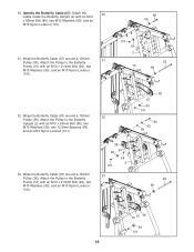
30. Attach the Pulley to the Butterfly Frame (10) with an M10 x 213mm Bolt (92), two M10 Washers (99), and an M10 Nylon Locknut (101). 80 99 101 67 99 2 92 10 99 32. Wrap the Butterfly Cable (67) around a 100mm 31 Pulley (38). Attach the Pulley to the Butterfly Frame (10) with an M10 x 213mm Bolt (92), two M10 Washers (99), and an M10 Nylon Locknut (101). 38 99 67 69 2 101 33 38 67 99 101 80 99 69 92 99 10 67 38 99 101 16 Attach the Pulley to the Butterfly Upright (2) with an M10 x 65mm Bolt (80), two M10 Washers (99), and an M10 Nylon Locknut (101). 31...
30. Attach the Pulley to the Butterfly Frame (10) with an M10 x 213mm Bolt (92), two M10 Washers (99), and an M10 Nylon Locknut (101). 80 99 101 67 99 2 92 10 99 32. Wrap the Butterfly Cable (67) around a 100mm 31 Pulley (38). Attach the Pulley to the Butterfly Frame (10) with an M10 x 213mm Bolt (92), two M10 Washers (99), and an M10 Nylon Locknut (101). 38 99 67 69 2 101 33 38 67 99 101 80 99 69 92 99 10 67 38 99 101 16 Attach the Pulley to the Butterfly Upright (2) with an M10 x 65mm Bolt (80), two M10 Washers (99), and an M10 Nylon Locknut (101). 31...
English Manual
Page 17
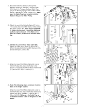
Note: Do not complete- Wrap the Lower Short Stack Cable (64) under a 100mm Pulley (38). Make sure the Cable Trap is oriented to the Base (1) with an M10 x 45mm Bolt (51). ly tighten the Locknut; Identify the Lower Short Stack Cable (64). 36 Attach the Cable to hold the Cable in the groove of the Pulley. 17 1 100 64 90 42 51 38 101 64 38 1 68 64 51 Note: The following steps are shown from the 38 back of the Cable show 40 past the Locknut, as shown in the groove of the Butterfly Cable (67) to the Double "U"-bracket (42) with an M10 x 50mm Bolt (81) and an ...
Note: Do not complete- Wrap the Lower Short Stack Cable (64) under a 100mm Pulley (38). Make sure the Cable Trap is oriented to the Base (1) with an M10 x 45mm Bolt (51). ly tighten the Locknut; Identify the Lower Short Stack Cable (64). 36 Attach the Cable to hold the Cable in the groove of the Pulley. 17 1 100 64 90 42 51 38 101 64 38 1 68 64 51 Note: The following steps are shown from the 38 back of the Cable show 40 past the Locknut, as shown in the groove of the Butterfly Cable (67) to the Double "U"-bracket (42) with an M10 x 50mm Bolt (81) and an ...
English Manual
Page 18
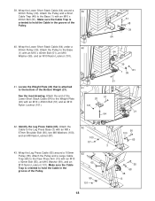
39. Wrap the Lower Short Stack Cable (64) under a 90mm Pulley (39). Identify the Leg Press Cable (65). Wrap the Lower Short Stack Cable (64) around a 100mm Pulley (38). Attach the Pulley and a Large Cable Trap (68) to the Rear Press Arm (13) with an M8 x 67mm Shoulder Bolt (90), two M8 Washers (100), and an M8 Nylon Locknut (87). 42 100 87 43. Attach the Cable to the Weight Plate (20) with an M10 x 45mm Bolt (51) and an M10 Nylon Locknut (101). 40 64 39 101 1 99 51 41 51 20 101 21 64 42. Locate the Weight Plate (20) that is attached to the bottom of the Lower Short ...
39. Wrap the Lower Short Stack Cable (64) under a 90mm Pulley (39). Identify the Leg Press Cable (65). Wrap the Lower Short Stack Cable (64) around a 100mm Pulley (38). Attach the Pulley and a Large Cable Trap (68) to the Rear Press Arm (13) with an M8 x 67mm Shoulder Bolt (90), two M8 Washers (100), and an M8 Nylon Locknut (87). 42 100 87 43. Attach the Cable to the Weight Plate (20) with an M10 x 45mm Bolt (51) and an M10 Nylon Locknut (101). 40 64 39 101 1 99 51 41 51 20 101 21 64 42. Locate the Weight Plate (20) that is attached to the bottom of the Lower Short ...
English Manual
Page 19
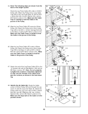
Attach the Pulley and a Long Cable Trap (68) to the Leg Press Base (3) with an M10 x 65mm Bolt (80), two M10 Washers (99), two 12.5mm Spacers (69), and an M10 Nylon Locknut (101). Make sure the Cable Trap is oriented to the M10 x 121mm Carriage Bolt (49) in the groove of the Pulley. 45. Wap the Leg Press Cable (65) under a 100mm Pulley (38). Attach the end of the weight system. Identify the Ab Cable (66). Attach the Pulley inside the Leg Lever with an M10 x 92mm Bolt (55), an M10 Washer (99), and an M10 Nylon Locknut (101). Route the Leg Press Cable (65) under a ...
Attach the Pulley and a Long Cable Trap (68) to the Leg Press Base (3) with an M10 x 65mm Bolt (80), two M10 Washers (99), two 12.5mm Spacers (69), and an M10 Nylon Locknut (101). Make sure the Cable Trap is oriented to the M10 x 121mm Carriage Bolt (49) in the groove of the Pulley. 45. Wap the Leg Press Cable (65) under a 100mm Pulley (38). Attach the end of the weight system. Identify the Ab Cable (66). Attach the Pulley inside the Leg Lever with an M10 x 92mm Bolt (55), an M10 Washer (99), and an M10 Nylon Locknut (101). Route the Leg Press Cable (65) under a ...
English Manual
Page 20
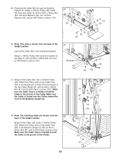
Make sure the Cable Trap is routed over a 100mm Pulley 51 (38). Make sure the Cable is oriented to the Butterfly Upright (2) with an M10 x 65mm Bolt (80), two M10 Washers (99), two 12.5mm Spacers (69), and an M10 Nylon Locknut (101). 49 66 2 5 38 101 99 69 69 99 80 50. Attach the Pulley and a Long Cable Trap (68) to hold the Cable in the groove of the Pulley. Lay the Ab Cable (66) in the groove of the Pulley. 41 2 101 68 81 38 66 81 66 38 68 2 101 20 Make sure the Cable Trap is shown from the 52 back of the weight system. Attach a 100mm Pulley (38) inside the ...
Make sure the Cable Trap is routed over a 100mm Pulley 51 (38). Make sure the Cable is oriented to the Butterfly Upright (2) with an M10 x 65mm Bolt (80), two M10 Washers (99), two 12.5mm Spacers (69), and an M10 Nylon Locknut (101). 49 66 2 5 38 101 99 69 69 99 80 50. Attach the Pulley and a Long Cable Trap (68) to hold the Cable in the groove of the Pulley. Lay the Ab Cable (66) in the groove of the Pulley. 41 2 101 68 81 38 66 81 66 38 68 2 101 20 Make sure the Cable Trap is shown from the 52 back of the weight system. Attach a 100mm Pulley (38) inside the ...