

English Manual
Page 1
Model No. 831.14922.2 Serial No. WEIGHT SYSTEM EXERCISER User’'s Manual Serial Number Decal (under the seat) •• Assembly •• Operation •• Maintenance •• Part List and Drawing Sears, Roebuck and Co. Keep this equipment. Hoffman Estates, IL 60179 CAUTION Read all precautions and instructions in the space above for future reference. Write the serial number in this manual before using this manual for reference.
Model No. 831.14922.2 Serial No. WEIGHT SYSTEM EXERCISER User’'s Manual Serial Number Decal (under the seat) •• Assembly •• Operation •• Maintenance •• Part List and Drawing Sears, Roebuck and Co. Keep this equipment. Hoffman Estates, IL 60179 CAUTION Read all precautions and instructions in the space above for future reference. Write the serial number in this manual before using this manual for reference.
English Manual
Page 2
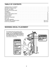
... or illegible, call 1-877-992-5999 and request a free replacement decal. TABLE OF CONTENTS WARNING DECAL PLACEMENT 2 IMPORTANT PRECAUTIONS 3 BEFORE YOU BEGIN 4 PART IDENTIFICATION CHART 5 ASSEMBLY 6 ADJUSTMENT 21 WEIGHT RESISTANCE CHART 23 CABLE DIAGRAM 24 MAINTENANCE 25 EXERCISE GUIDELINES 26 PART LIST 29 EXPLODED DRAWING 30 ORDERING REPLACEMENT PARTS Back Cover...
... or illegible, call 1-877-992-5999 and request a free replacement decal. TABLE OF CONTENTS WARNING DECAL PLACEMENT 2 IMPORTANT PRECAUTIONS 3 BEFORE YOU BEGIN 4 PART IDENTIFICATION CHART 5 ASSEMBLY 6 ADJUSTMENT 21 WEIGHT RESISTANCE CHART 23 CABLE DIAGRAM 24 MAINTENANCE 25 EXERCISE GUIDELINES 26 PART LIST 29 EXPLODED DRAWING 30 ORDERING REPLACEMENT PARTS Back Cover...
English Manual
Page 5
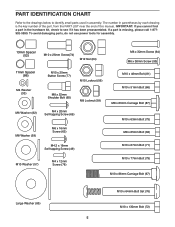
To avoid damaging parts, do not use power tools for assembly. 13mm Spacer (52) M10 x 25mm Screw(74) M12 Nut (84) M6 x 32mm Screw (64) M6 x 38mm Screw (95) 11mm Spacer (86) M4 Washer (33) M10 x ... call 1-877992-5999. If a part is the key number of the part, from the PART LIST near the end of this manual. The number in assembly. PART IDENTIFICATION CHART Refer to the drawings below to see if it has been preassembled.
To avoid damaging parts, do not use power tools for assembly. 13mm Spacer (52) M10 x 25mm Screw(74) M12 Nut (84) M6 x 32mm Screw (64) M6 x 38mm Screw (95) 11mm Spacer (86) M4 Washer (33) M10 x ... call 1-877992-5999. If a part is the key number of the part, from the PART LIST near the end of this manual. The number in assembly. PART IDENTIFICATION CHART Refer to the drawings below to see if it has been preassembled.
English Manual
Page 6
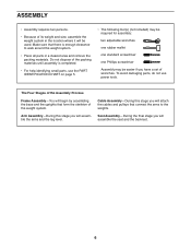
...is completed. •• For help identifying small parts, use power tools. Do not dispose of the packing materials until assembly is enough clearance to the weights. Cable Assembly—-During this stage you will be easier if you have a set of wrenches. To avoid damaging parts, do not ...that form the skeleton of the weight system. The Four Stages of the Assembly Process Frame Assembly—-You will assemble the arms and the leg lever. Seat Assembly—-During the final stage you will begin by assembling the base and the uprights that connect the arms to walk around the ...
...is completed. •• For help identifying small parts, use power tools. Do not dispose of the packing materials until assembly is enough clearance to the weights. Cable Assembly—-During this stage you will be easier if you have a set of wrenches. To avoid damaging parts, do not ...that form the skeleton of the weight system. The Four Stages of the Assembly Process Frame Assembly—-You will assemble the arms and the leg lever. Seat Assembly—-During the final stage you will begin by assembling the base and the uprights that connect the arms to walk around the ...

English Manual
Page 7
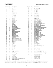
the Foot Plate must pivot easily. 56 1 72 38 2. Do not tighten the Locknuts yet. 21 2 71 1 71 57 56 57 7 Attach the Foot Plate (38) to the Stabilizer (2) with an M10 x 130mm Bolt (72) and an M10 Locknut (56). Do not overtighten the Locknut; Frame Assembly 1 1. Attach the Weight Guides (21) and the Base 2 (1) to the Base (1) with two M10 x 67mm Bolts (71), two M10 Washers (57), and two M10 Locknuts (56).
the Foot Plate must pivot easily. 56 1 72 38 2. Do not tighten the Locknuts yet. 21 2 71 1 71 57 56 57 7 Attach the Foot Plate (38) to the Stabilizer (2) with an M10 x 130mm Bolt (72) and an M10 Locknut (56). Do not overtighten the Locknut; Frame Assembly 1 1. Attach the Weight Guides (21) and the Base 2 (1) to the Base (1) with two M10 x 67mm Bolts (71), two M10 Washers (57), and two M10 Locknuts (56).

English Manual
Page 11
... x 25mm Button Screws (77) and two M10 Washers (57). Do not overtighten the Locknut; Slide the Large Foam Pad onto the Left Arm (10). 10. Assemble the Right Arm (9) in the Upright (3). 69 5 40 12. Insert the Arm Pins (40) into the indicated holes in the same way. 11 40 40... Frame (5) to the Left Arm (10) 12 9 with two M4 x 20mm Self-tapping Screws (69). the Cable Pivot must pivot easily. 56 5 4 Grease 79 Arm Assembly 11 11. Attach a Handle (11) to an M10 x 51mm Bolt (66).
... x 25mm Button Screws (77) and two M10 Washers (57). Do not overtighten the Locknut; Slide the Large Foam Pad onto the Left Arm (10). 10. Assemble the Right Arm (9) in the Upright (3). 69 5 40 12. Insert the Arm Pins (40) into the indicated holes in the same way. 11 40 40... Frame (5) to the Left Arm (10) 12 9 with two M4 x 20mm Self-tapping Screws (69). the Cable Pivot must pivot easily. 56 5 4 Grease 79 Arm Assembly 11 11. Attach a Handle (11) to an M10 x 51mm Bolt (66).

English Manual
Page 12
... Bushings (44). Do not overtighten the Locknut; 13. Apply grease to an M10 x 86mm Carriage Bolt 13 (67) and to identify the cables as you assemble them. Attach the Right Arm (9) to the Pivot Frame (5) with the M8 x 22mm Shoulder Bolt (65) and an M8 Locknut (58). 58 39 54 Grease... 65 12 Attach the Left Arm (10) to the Pivot Frame (5) in the same way. 9 5 67 20 Grease 44 57 56 Grease 10 44 Cable Assembly 14 14. Identify the Arm Cable (54).
... Bushings (44). Do not overtighten the Locknut; 13. Apply grease to an M10 x 86mm Carriage Bolt 13 (67) and to identify the cables as you assemble them. Attach the Right Arm (9) to the Pivot Frame (5) with the M8 x 22mm Shoulder Bolt (65) and an M8 Locknut (58). 58 39 54 Grease... 65 12 Attach the Left Arm (10) to the Pivot Frame (5) in the same way. 9 5 67 20 Grease 44 57 56 Grease 10 44 Cable Assembly 14 14. Identify the Arm Cable (54).

English Manual
Page 18
...) into the Upright and one of the Weight Selector (24). Tighten the M12 Nut (84) against the Large Washer (85). 55 84 85 24 Seat Assembly 31 31. 30. Place a Large Washer (85) on top of the holes in the Backrest Frame. 91 61 62 82 64 3 32. Tighten the High...
...) into the Upright and one of the Weight Selector (24). Tighten the M12 Nut (84) against the Large Washer (85). 55 84 85 24 Seat Assembly 31 31. 30. Place a Large Washer (85) on top of the holes in the Backrest Frame. 91 61 62 82 64 3 32. Tighten the High...

English Manual
Page 24
... the proper route of the cables. Make sure that the cables, cable traps, and guards are not assembled correctly, the weight system will not function properly and damage may occur. If the cables are assembled correctly. CABLE DIAGRAM The drawings below shows the proper routing of that cable. Use the drawings to...
... the proper route of the cables. Make sure that the cables, cable traps, and guards are not assembled correctly, the weight system will not function properly and damage may occur. If the cables are assembled correctly. CABLE DIAGRAM The drawings below shows the proper routing of that cable. Use the drawings to...
English Manual
Page 29
..., see the back cover of this manual. *These parts are subject to change without notice. If a part is missing, please call 1-877-992-5999. 29 Assembly Tool Note: Specifications are not illustrated. Description Key No. PART LIST Model No. 831.14922.2 R0912A Key No. Qty. Qty. User’'s Manual * –...
..., see the back cover of this manual. *These parts are subject to change without notice. If a part is missing, please call 1-877-992-5999. 29 Assembly Tool Note: Specifications are not illustrated. Description Key No. PART LIST Model No. 831.14922.2 R0912A Key No. Qty. Qty. User’'s Manual * –...


