
English Manual
Page 1
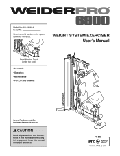
Write the serial number in this manual before using this manual for reference. Hoffman Estates, IL 60179 CAUTION Read all precautions and instructions in the space above for future reference. Keep this equipment. Model No. 831.14922.2 Serial No. WEIGHT SYSTEM EXERCISER User’'s Manual Serial Number Decal (under the seat) •• Assembly •• Operation •• Maintenance •• Part List and Drawing Sears, Roebuck and Co.
Write the serial number in this manual before using this manual for reference. Hoffman Estates, IL 60179 CAUTION Read all precautions and instructions in the space above for future reference. Keep this equipment. Model No. 831.14922.2 Serial No. WEIGHT SYSTEM EXERCISER User’'s Manual Serial Number Decal (under the seat) •• Assembly •• Operation •• Maintenance •• Part List and Drawing Sears, Roebuck and Co.
English Manual
Page 2
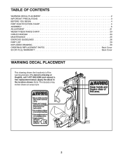
Apply the decal in the location shown. Note: The decal(s) may not be shown at actual size. 2 If a decal is missing or illegible, call 1-877-992-5999 and request a free replacement decal. TABLE OF CONTENTS WARNING DECAL PLACEMENT 2 IMPORTANT PRECAUTIONS 3 BEFORE YOU BEGIN 4 PART IDENTIFICATION CHART 5 ASSEMBLY 6 ADJUSTMENT 21 WEIGHT RESISTANCE CHART 23 CABLE DIAGRAM 24 MAINTENANCE 25 EXERCISE GUIDELINES 26 PART LIST 29 EXPLODED DRAWING 30 ORDERING REPLACEMENT PARTS Back Cover 90 DAY FULL WARRANTY Back Cover WARNING DECAL PLACEMENT This drawing shows the location(s) of the ...
Apply the decal in the location shown. Note: The decal(s) may not be shown at actual size. 2 If a decal is missing or illegible, call 1-877-992-5999 and request a free replacement decal. TABLE OF CONTENTS WARNING DECAL PLACEMENT 2 IMPORTANT PRECAUTIONS 3 BEFORE YOU BEGIN 4 PART IDENTIFICATION CHART 5 ASSEMBLY 6 ADJUSTMENT 21 WEIGHT RESISTANCE CHART 23 CABLE DIAGRAM 24 MAINTENANCE 25 EXERCISE GUIDELINES 26 PART LIST 29 EXPLODED DRAWING 30 ORDERING REPLACEMENT PARTS Back Cover 90 DAY FULL WARRANTY Back Cover WARNING DECAL PLACEMENT This drawing shows the location(s) of the ...
English Manual
Page 3
Use the weight system only as described in serious injury or death. Always wear athletic shoes for personal injury or property damage sustained by persons weighing more than 300 lbs. (136 kg). 9. If the cables bind while you experience pain while exercising, stop immediately and make sure that could cause the weight system to protect the floor. 13. Never release the arms, leg lever, lat bar, or handle strap while weights are on the pulleys. 5. Over exercising may result in this manual and all warnings on the pulleys at all parts regularly. system. Keep hands and...
Use the weight system only as described in serious injury or death. Always wear athletic shoes for personal injury or property damage sustained by persons weighing more than 300 lbs. (136 kg). 9. If the cables bind while you experience pain while exercising, stop immediately and make sure that could cause the weight system to protect the floor. 13. Never release the arms, leg lever, lat bar, or handle strap while weights are on the pulleys. 5. Over exercising may result in this manual and all warnings on the pulleys at all parts regularly. system. Keep hands and...
English Manual
Page 4
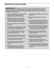
... and serial number before using the weight system. For your cardiovascular system, the weight system will help us . To help you for selecting the versatile WEIDER PRO® 6900 weight system.
... and serial number before using the weight system. For your cardiovascular system, the weight system will help us . To help you for selecting the versatile WEIDER PRO® 6900 weight system.
English Manual
Page 5
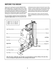
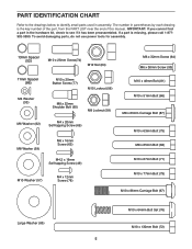
PART IDENTIFICATION CHART Refer to the drawings below to see if it has been preassembled. To avoid damaging parts, do not use power tools for assembly. 13mm Spacer (52) M10 x 25mm Screw(74) M12 Nut (84) M6 x 32mm Screw (64) M6 x 38mm Screw (95) 11mm Spacer (86) M4 Washer (33) M10 x 25mm Button Screw (77) M10 Locknut (56) M8 x 22mm Shoulder Bolt (65) M8 Locknut (58) M6 Washer (82) M4 x 20mm Self-tapping Screw (69) M8 Washer (59) M6 x 16mm Screw (62) M10 x 46mm Bolt (81) M10 x 51mm Bolt (66) M8 x 63mm Carriage Bolt (87) M10 x 63mm Bolt (75) M8 x 65mm Bolt (68) M4.2 x 16mm ...
PART IDENTIFICATION CHART Refer to the drawings below to see if it has been preassembled. To avoid damaging parts, do not use power tools for assembly. 13mm Spacer (52) M10 x 25mm Screw(74) M12 Nut (84) M6 x 32mm Screw (64) M6 x 38mm Screw (95) 11mm Spacer (86) M4 Washer (33) M10 x 25mm Button Screw (77) M10 Locknut (56) M8 x 22mm Shoulder Bolt (65) M8 Locknut (58) M6 Washer (82) M4 x 20mm Self-tapping Screw (69) M8 Washer (59) M6 x 16mm Screw (62) M10 x 46mm Bolt (81) M10 x 51mm Bolt (66) M8 x 63mm Carriage Bolt (87) M10 x 63mm Bolt (75) M8 x 65mm Bolt (68) M4.2 x 16mm ...
English Manual
Page 6
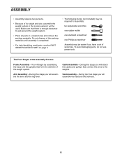
To avoid damaging parts, do not use the PART IDENTIFICATION CHART on page 5. •• The following tool(s) (not included) may be required for assembly: two adjustable wrenches one rubber mallet one standard screwdriver one Phillips screwdriver Assembly may be easier if you will attach the cables and pulleys that connect the arms to walk around the weight system. •• Place all parts in the location where it will assemble the seat and the backrest. 6 Seat Assembly—-During the final stage you will assemble the arms and the leg lever. Cable Assembly—-...
To avoid damaging parts, do not use the PART IDENTIFICATION CHART on page 5. •• The following tool(s) (not included) may be required for assembly: two adjustable wrenches one rubber mallet one standard screwdriver one Phillips screwdriver Assembly may be easier if you will attach the cables and pulleys that connect the arms to walk around the weight system. •• Place all parts in the location where it will assemble the seat and the backrest. 6 Seat Assembly—-During the final stage you will assemble the arms and the leg lever. Cable Assembly—-...

English Manual
Page 7
Do not tighten the Locknuts yet. 21 2 71 1 71 57 56 57 7 Frame Assembly 1 1. the Foot Plate must pivot easily. 56 1 72 38 2. Attach the Weight Guides (21) and the Base 2 (1) to the Base (1) with two M10 x 67mm Bolts (71), two M10 Washers (57), and two M10 Locknuts (56). Attach the Foot Plate (38) to the Stabilizer (2) with an M10 x 130mm Bolt (72) and an M10 Locknut (56). Do not overtighten the Locknut;
Do not tighten the Locknuts yet. 21 2 71 1 71 57 56 57 7 Frame Assembly 1 1. the Foot Plate must pivot easily. 56 1 72 38 2. Attach the Weight Guides (21) and the Base 2 (1) to the Base (1) with two M10 x 67mm Bolts (71), two M10 Washers (57), and two M10 Locknuts (56). Attach the Foot Plate (38) to the Stabilizer (2) with an M10 x 130mm Bolt (72) and an M10 Locknut (56). Do not overtighten the Locknut;

English Manual
Page 8
Do not tighten the Locknuts yet. 3 4. Do not tighten the Locknuts yet. 58 58 1 87 7 58 58 1 87 8 3. Attach the Front Leg (7) to the Base (1) with two M8 x 63mm Carriage Bolts (87) and two M8 4 Locknuts (58). Attach the Upright (3) to the Base (1) with two 3 M8 x 63mm Carriage Bolts (87) and two M8 Locknuts (58).
Do not tighten the Locknuts yet. 3 4. Do not tighten the Locknuts yet. 58 58 1 87 7 58 58 1 87 8 3. Attach the Front Leg (7) to the Base (1) with two M8 x 63mm Carriage Bolts (87) and two M8 4 Locknuts (58). Attach the Upright (3) to the Base (1) with two 3 M8 x 63mm Carriage Bolts (87) and two M8 Locknuts (58).

English Manual
Page 9
5. Apply some of the included grease inside the indicated holes in the same way. 6 7 59 58 3 68 68 68 68 58 59 6. Do not tighten the Locknuts yet. Insert the Weight Selector (24) into the nine Weights (22). Slide the Weights onto the Weight Guides (21). Then, slide the Weight onto the Weight Guides (21). 21 22 Grease 22 Pin Hole Pin 24 27 9 Attach the Seat Tube (6) to the Upright (3) with 5 two M8 x 65mm Bolts (68), two M8 Washers (59), and two M8 Locknuts (58). Slide the two Weight Bumpers (27) onto the Weight Guides (21). 6 Orient nine Weights (22) so ...
5. Apply some of the included grease inside the indicated holes in the same way. 6 7 59 58 3 68 68 68 68 58 59 6. Do not tighten the Locknuts yet. Insert the Weight Selector (24) into the nine Weights (22). Slide the Weights onto the Weight Guides (21). Then, slide the Weight onto the Weight Guides (21). 21 22 Grease 22 Pin Hole Pin 24 27 9 Attach the Seat Tube (6) to the Upright (3) with 5 two M8 x 65mm Bolts (68), two M8 Washers (59), and two M8 Locknuts (58). Slide the two Weight Bumpers (27) onto the Weight Guides (21). 6 Orient nine Weights (22) so ...
English Manual
Page 10
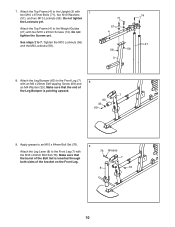
Do not tighten the Screws yet. Make sure that the barrel of the bracket on the Front Leg. 76 Grease 7 8 76 10 Apply grease to an M10 x 64mm Bolt Set (76). 9 Attach the Leg Lever (8) to the Front Leg (7) with an M4 x 20mm Self-tapping Screw (69) and an M4 Washer (33). Do not tighten the Locknuts yet. Tighten the M10 Locknuts (56) and the M8 Locknuts (58). 74 71 57 4 21 56 56 3 8. Attach the Leg Bumper (60) to the Weight Guides (21) with 7 two M10 x 67mm Bolts (71), two M10 Washers (57), and two M10 Locknuts (56). Attach the Top Frame (4) to the Front Leg (7) 8 ...
Do not tighten the Screws yet. Make sure that the barrel of the bracket on the Front Leg. 76 Grease 7 8 76 10 Apply grease to an M10 x 64mm Bolt Set (76). 9 Attach the Leg Lever (8) to the Front Leg (7) with an M4 x 20mm Self-tapping Screw (69) and an M4 Washer (33). Do not tighten the Locknuts yet. Tighten the M10 Locknuts (56) and the M8 Locknuts (58). 74 71 57 4 21 56 56 3 8. Attach the Leg Bumper (60) to the Weight Guides (21) with 7 two M10 x 67mm Bolts (71), two M10 Washers (57), and two M10 Locknuts (56). Attach the Top Frame (4) to the Front Leg (7) 8 ...

English Manual
Page 11
the Cable Pivot must pivot easily. 56 5 4 Grease 79 Arm Assembly 11 11. Slide the Large Foam Pad onto the Left Arm (10). Attach a Handle (11) to the Left Arm (10) with the M10 x 77mm Bolt (79) and an M10 Locknut (56). Assemble the Right Arm (9) in the Upright (3). 69 5 40 12. Apply grease to an M10 x 77mm Bolt (79). 10 Attach the Pivot Frame (5) to the Pivot Frame (5) with soapy water. 10. Do not overtighten the Locknut; Wet the inside of a Large Foam Pad (42) with two M4 x 20mm Self-tapping Screws (69). the Pivot Frame must pivot easily. Insert the Arm Pins (...
the Cable Pivot must pivot easily. 56 5 4 Grease 79 Arm Assembly 11 11. Slide the Large Foam Pad onto the Left Arm (10). Attach a Handle (11) to the Left Arm (10) with the M10 x 77mm Bolt (79) and an M10 Locknut (56). Assemble the Right Arm (9) in the Upright (3). 69 5 40 12. Apply grease to an M10 x 77mm Bolt (79). 10 Attach the Pivot Frame (5) to the Pivot Frame (5) with soapy water. 10. Do not overtighten the Locknut; Wet the inside of a Large Foam Pad (42) with two M4 x 20mm Self-tapping Screws (69). the Pivot Frame must pivot easily. Insert the Arm Pins (...

English Manual
Page 12
Do not overtighten the Locknut; Identify the Arm Cable (54). Attach the Arm Cable (54) to an M8 x 22mm Shoulder Bolt (65). the Left Arm must pivot easily. Apply grease to the left Cable Pivot (39) with the M10 x 86mm Carriage Bolt (67), a Carriage Bolt Bushing (20), the two Arm Bushings (44), an M10 Washer (57), and an M10 Locknut (56). Attach the Right Arm (9) to the Pivot Frame (5) with the M8 x 22mm Shoulder Bolt (65) and an M8 Locknut (58). 58 39 54 Grease 65 12 Attach the Left Arm (10) to the Pivot Frame (5) in the same way. 9 5 67 20 Grease 44 57 56 Grease ...
Do not overtighten the Locknut; Identify the Arm Cable (54). Attach the Arm Cable (54) to an M8 x 22mm Shoulder Bolt (65). the Left Arm must pivot easily. Apply grease to the left Cable Pivot (39) with the M10 x 86mm Carriage Bolt (67), a Carriage Bolt Bushing (20), the two Arm Bushings (44), an M10 Washer (57), and an M10 Locknut (56). Attach the Right Arm (9) to the Pivot Frame (5) with the M8 x 22mm Shoulder Bolt (65) and an M8 Locknut (58). 58 39 54 Grease 65 12 Attach the Left Arm (10) to the Pivot Frame (5) in the same way. 9 5 67 20 Grease 44 57 56 Grease ...

English Manual
Page 13
15. Identify the two V-pulleys (46), the nine Thick 15 Pulleys (not shown), and the two Thin Pulleys (not shown). Route the Arm Cable (54) around a Thick Pulley (48). 16 Attach the Thick Pulley (48) and two Half Guards (43) to the Double U-bracket (63) with an M10 x 63mm Bolt (75) and an M10 Locknut (56). Make sure that the Large Cable Trap (50) is oriented to the Upright (3) with an M10 x 46mm Bolt (81) and an M10 Locknut (56). Route the Arm Cable (54) over a V-pulley (46). Route the Arm Cable (54) over a V-pulley (46). 17 Attach the V-pulley (46), a Large Cable Trap (50...
15. Identify the two V-pulleys (46), the nine Thick 15 Pulleys (not shown), and the two Thin Pulleys (not shown). Route the Arm Cable (54) around a Thick Pulley (48). 16 Attach the Thick Pulley (48) and two Half Guards (43) to the Double U-bracket (63) with an M10 x 63mm Bolt (75) and an M10 Locknut (56). Make sure that the Large Cable Trap (50) is oriented to the Upright (3) with an M10 x 46mm Bolt (81) and an M10 Locknut (56). Route the Arm Cable (54) over a V-pulley (46). Route the Arm Cable (54) over a V-pulley (46). 17 Attach the V-pulley (46), a Large Cable Trap (50...

English Manual
Page 14
Identify the Low Cable (53). Route the Low Cable through the Leg Lever (8) and the Front Leg (7). Apply grease to the right Cable Pivot (39) with the M8 x 22mm Shoulder Bolt (65) and an M8 Locknut (58). 18 Grease 65 54 39 58 19. Attach a Thick Pulley (48) inside the Front Leg (7), above the Low Cable (53), with an M10 x 67mm Bolt (71), two M10 Washers (57), two 13mm Spacers (52), and an M10 Locknut (56). 20 56 57 52 7 48 53 52 57 71 14 Attach a Thick Pulley (48) inside the Leg Lever (8), above the Low Cable (53), with an M10 x 67mm Bolt (71), two M10 Washers (57), two 13mm ...
Identify the Low Cable (53). Route the Low Cable through the Leg Lever (8) and the Front Leg (7). Apply grease to the right Cable Pivot (39) with the M8 x 22mm Shoulder Bolt (65) and an M8 Locknut (58). 18 Grease 65 54 39 58 19. Attach a Thick Pulley (48) inside the Front Leg (7), above the Low Cable (53), with an M10 x 67mm Bolt (71), two M10 Washers (57), two 13mm Spacers (52), and an M10 Locknut (56). 20 56 57 52 7 48 53 52 57 71 14 Attach a Thick Pulley (48) inside the Leg Lever (8), above the Low Cable (53), with an M10 x 67mm Bolt (71), two M10 Washers (57), two 13mm ...

English Manual
Page 15
Make sure that the Half Guards are on the outside of the Double U-bracket as shown. 56 43 53 48 1 43 81 15 Make sure that the Half Guards are on the outside of the bracket as shown. 43 56 53 63 43 48 81 23. Route the Low Cable (53) under a Thick Pulley (48). Attach the Thick Pulley (48) and two Half Guards (43) to the Double U-bracket (63) with an M10 x 46mm Bolt (81) and an M10 Locknut (56). Route the Low Cable (53) over a Thick 22 Pulley (48). Attach the Thick Pulley (48) and two Half Guards (43) to the Base (1) with an M10 x 46mm Bolt (81) and an M10 Locknut (...
Make sure that the Half Guards are on the outside of the Double U-bracket as shown. 56 43 53 48 1 43 81 15 Make sure that the Half Guards are on the outside of the bracket as shown. 43 56 53 63 43 48 81 23. Route the Low Cable (53) under a Thick Pulley (48). Attach the Thick Pulley (48) and two Half Guards (43) to the Double U-bracket (63) with an M10 x 46mm Bolt (81) and an M10 Locknut (56). Route the Low Cable (53) over a Thick 22 Pulley (48). Attach the Thick Pulley (48) and two Half Guards (43) to the Base (1) with an M10 x 46mm Bolt (81) and an M10 Locknut (...

English Manual
Page 16
Attach the Low Cable (53) to the U-bracket (45) 24 with an M10 x 67mm Bolt (71), an M10 Washer (57), and an 11mm Spacer (86). Identify the High Cable (55). Make sure that only two threads are showing above the Locknut. 58 45 59 53 45 58 53 25. it should be threaded onto the end of the Low Cable (53) so that the Thin Pulley does not fall out of the Top Frame while you complete steps 27 and 28. 55 47 4 86 57 71 16 24. Do not overtighten the M8 Locknut (58); See the inset drawing. Route the High Cable upward through the Top Frame (4) and 25 over a Thin Pulley (47) ...
Attach the Low Cable (53) to the U-bracket (45) 24 with an M10 x 67mm Bolt (71), an M10 Washer (57), and an 11mm Spacer (86). Identify the High Cable (55). Make sure that only two threads are showing above the Locknut. 58 45 59 53 45 58 53 25. it should be threaded onto the end of the Low Cable (53) so that the Thin Pulley does not fall out of the Top Frame while you complete steps 27 and 28. 55 47 4 86 57 71 16 24. Do not overtighten the M8 Locknut (58); See the inset drawing. Route the High Cable upward through the Top Frame (4) and 25 over a Thin Pulley (47) ...

English Manual
Page 17
27. Route the High Cable (55) upward through the Top Frame (4). Attach the Thick Pulley (48) inside the Top Frame (4) with an M10 x 51mm Bolt (66) and an M10 Locknut (56). Wrap the High Cable (55) under a Thick 27 Pulley (48). Make sure that the Small Cable Trap (51) is oriented to the upper hole in the U-bracket (45) with the M10 x 67mm Bolt (71) used in the groove of the Thick Pulley (48) and that the Half Guards (43) are on the outside of the U-bracket (45). 28. Attach the Thick Pulley (48), a Small Cable Trap (51), and two Half Guards (43) to hold the High Cable (55) in ...
27. Route the High Cable (55) upward through the Top Frame (4). Attach the Thick Pulley (48) inside the Top Frame (4) with an M10 x 51mm Bolt (66) and an M10 Locknut (56). Wrap the High Cable (55) under a Thick 27 Pulley (48). Make sure that the Small Cable Trap (51) is oriented to the upper hole in the U-bracket (45) with the M10 x 67mm Bolt (71) used in the groove of the Thick Pulley (48) and that the Half Guards (43) are on the outside of the U-bracket (45). 28. Attach the Thick Pulley (48), a Small Cable Trap (51), and two Half Guards (43) to hold the High Cable (55) in ...

English Manual
Page 18
Place a Large Washer (85) on top of the holes in the Seat Frame. Attach the Seat (15) to the Backrest Frame (61) with two M6 x 16mm Screws (62), an M6 x 38mm 32 Screw (95), and an M6 Washer (82). 15 Insert the Seat Frame (73) into the Seat Tube (6) and tighten a Long Knob (91) into the Seat Tube and one of the Weight Selector (24). Tighten the High Cable (55) into the Upright and one of the holes in the Backrest Frame. 91 61 62 82 64 3 32. Attach the Backrest (16) to the Seat Frame (73) with two M6 x 16mm Screws (62), an M6 x 32mm Screw (64), and an M6 Washer (82). 16...
Place a Large Washer (85) on top of the holes in the Seat Frame. Attach the Seat (15) to the Backrest Frame (61) with two M6 x 16mm Screws (62), an M6 x 38mm 32 Screw (95), and an M6 Washer (82). 15 Insert the Seat Frame (73) into the Seat Tube (6) and tighten a Long Knob (91) into the Seat Tube and one of the Weight Selector (24). Tighten the High Cable (55) into the Upright and one of the holes in the Backrest Frame. 91 61 62 82 64 3 32. Attach the Backrest (16) to the Seat Frame (73) with two M6 x 16mm Screws (62), an M6 x 32mm Screw (64), and an M6 Washer (82). 16...

English Manual
Page 19
33. Then, press a Pad Cap (34) into the Front Leg (7). Insert the Pad Tube (29) into each side of the Left Shroud (17) and the Shroud Support (19) with two M4.2 x 16mm Self-tapping Screws (49) and two M4 Washers (33). Do not tighten the Screws yet. 4 49 33 90 33 78 19 17 19 Then, attach a Shroud Clamp (90) to the left side of the Leg Lever (8). Slide a Small Foam Pad (28) onto each Small Foam Pad. 33 34 28 7 34 28 8 29 28 28 34 34 34. Slide a Small Foam Pad (28) onto each Small Foam Pad. Attach a Shroud Support (19) and the top of the 34 Left Shroud (17) to ...
33. Then, press a Pad Cap (34) into the Front Leg (7). Insert the Pad Tube (29) into each side of the Left Shroud (17) and the Shroud Support (19) with two M4.2 x 16mm Self-tapping Screws (49) and two M4 Washers (33). Do not tighten the Screws yet. 4 49 33 90 33 78 19 17 19 Then, attach a Shroud Clamp (90) to the left side of the Leg Lever (8). Slide a Small Foam Pad (28) onto each Small Foam Pad. 33 34 28 7 34 28 8 29 28 28 34 34 34. Slide a Small Foam Pad (28) onto each Small Foam Pad. Attach a Shroud Support (19) and the top of the 34 Left Shroud (17) to ...
English Manual
Page 20
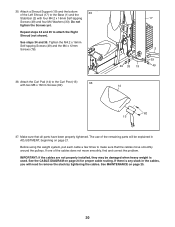
Attach the Curl Pad (14) to the Base (1) and the 35 Stabilizer (2) with two M6 x 16mm Screws (62). 17 2 1 33 49 33 19 49 14 62 13 37. If one of the remaining parts will need to remove the slack by tightening the cables. See MAINTENANCE on page 24 for proper cable routing. 35. Attach a Shroud Support (19) and the bottom of the Left Shroud (17) to the Curl Post (13) 36 with four M4.2 x 16mm Self-tapping Screws (49) and four M4 Washers (33). Tighten the M4.2 x 16mm Self-tapping Screws (49) and the M4 x 12mm Screws (78). 36. IMPORTANT: If the cables are not properly ...
Attach the Curl Pad (14) to the Base (1) and the 35 Stabilizer (2) with two M6 x 16mm Screws (62). 17 2 1 33 49 33 19 49 14 62 13 37. If one of the remaining parts will need to remove the slack by tightening the cables. See MAINTENANCE on page 24 for proper cable routing. 35. Attach a Shroud Support (19) and the bottom of the Left Shroud (17) to the Curl Post (13) 36 with four M4.2 x 16mm Self-tapping Screws (49) and four M4 Washers (33). Tighten the M4.2 x 16mm Self-tapping Screws (49) and the M4 x 12mm Screws (78). 36. IMPORTANT: If the cables are not properly ...
