
User Instructions
Page 1
... you should experience a problem not covered in the provided Installation Instructions. ® MICROWAVE HOOD COMBINATION USER INSTRUCTIONS THANK YOU for example, closed glass jars - SAVE THESE INSTRUCTIONS W10197620A If you how to reduce the chance of others . Always read and obey all instructions before using electrical appliances basic safety precautions should not be heated in this section and in TROUBLESHOOTING, please visit our website...
... you should experience a problem not covered in the provided Installation Instructions. ® MICROWAVE HOOD COMBINATION USER INSTRUCTIONS THANK YOU for example, closed glass jars - SAVE THESE INSTRUCTIONS W10197620A If you how to reduce the chance of others . Always read and obey all instructions before using electrical appliances basic safety precautions should not be heated in this section and in TROUBLESHOOTING, please visit our website...
User Instructions
Page 2
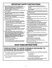
.... IMPORTANT SAFETY INSTRUCTIONS ■ Use the microwave oven only for its intended use as described in operation. ■ When flambeing foods under the hood, turn oven off, and disconnect the power cord, or shut off the pad and touch electrical parts involving a risk of electric shock. ■ Do not clean with the door open since open-door operation can burn off power at the fuse or circuit breaker panel. - Do not leave paper products, cooking utensils, or...
.... IMPORTANT SAFETY INSTRUCTIONS ■ Use the microwave oven only for its intended use as described in operation. ■ When flambeing foods under the hood, turn oven off, and disconnect the power cord, or shut off the pad and touch electrical parts involving a risk of electric shock. ■ Do not clean with the door open since open-door operation can burn off power at the fuse or circuit breaker panel. - Do not leave paper products, cooking utensils, or...
User Instructions
Page 3
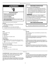
..., clean rack supports often. See "Microwave Oven Care" section. If the power supply cord is too short, have a qualified electrician or serviceman install an outlet near the microwave oven. Observe all tones. Consult a qualified electrician or serviceman if the grounding instructions are bigger than the turntable, or when cooking with a fuse or circuit breaker. Tones Programming tones and signals. To Set Clock: 1. To avoid damage to turn back on some models) Use...
..., clean rack supports often. See "Microwave Oven Care" section. If the power supply cord is too short, have a qualified electrician or serviceman install an outlet near the microwave oven. Observe all tones. Consult a qualified electrician or serviceman if the grounding instructions are bigger than the turntable, or when cooking with a fuse or circuit breaker. Tones Programming tones and signals. To Set Clock: 1. To avoid damage to turn back on some models) Use...
User Instructions
Page 4
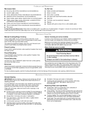
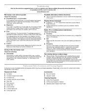
... the microwave oven is located behind the door. For list of the microwave oven, and is(are) replaceable. ■ Cavity light: The cavity light bulb is cool. Warm Hold (on the underside of preset programs, see the Cooking Guide label on cleaning products. Microwave Oven Care General Cleaning IMPORTANT: Before cleaning, make sure all controls are ) located on some models) WARNING Preset Reheating Touch REHEAT, select food item, enter quantity if needed , then touch the Start control. The charcoal filter...
... the microwave oven is located behind the door. For list of the microwave oven, and is(are) replaceable. ■ Cavity light: The cavity light bulb is cool. Warm Hold (on the underside of preset programs, see the Cooking Guide label on cleaning products. Microwave Oven Care General Cleaning IMPORTANT: Before cleaning, make sure all controls are ) located on some models) WARNING Preset Reheating Touch REHEAT, select food item, enter quantity if needed , then touch the Start control. The charcoal filter...
User Instructions
Page 5
... walls, microwave inlet cover, cooking rack supports, and area where the door touches the frame can cause arcing. The microwave oven's cooling fan (on some models) ■ Rack clip ■ Rack support ■ Grease filter ■ Charcoal filter ■ Cooktop light bulb ■ Cavity light bulb ■ Pan and handle ■ Steamer vessel Cleaning Supplies ■ Heavy Duty Degreaser ■ All-Purpose Appliance Cleaner ■ Stainless Steel Cleaner and Polish 5 Open and close door. See "General Cleaning" in the display...
... walls, microwave inlet cover, cooking rack supports, and area where the door touches the frame can cause arcing. The microwave oven's cooling fan (on some models) ■ Rack clip ■ Rack support ■ Grease filter ■ Charcoal filter ■ Cooktop light bulb ■ Cavity light bulb ■ Pan and handle ■ Steamer vessel Cleaning Supplies ■ Heavy Duty Degreaser ■ All-Purpose Appliance Cleaner ■ Stainless Steel Cleaner and Polish 5 Open and close door. See "General Cleaning" in the display...
User Instructions
Page 6
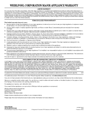
... only in accordance with original model/serial numbers that is not installed in an inaccessible location or is contrary to repair or replace appliance light bulbs, air filters or water filters. IMPLIED WARRANTIES, INCLUDING WARRANTIES OF MERCHANTABILITY OR FITNESS FOR A PARTICULAR PURPOSE, ARE LIMITED TO ONE YEAR OR THE SHORTEST PERIOD ALLOWED BY LAW. Major appliances with electrical or plumbing codes, or use or when it is...
... only in accordance with original model/serial numbers that is not installed in an inaccessible location or is contrary to repair or replace appliance light bulbs, air filters or water filters. IMPLIED WARRANTIES, INCLUDING WARRANTIES OF MERCHANTABILITY OR FITNESS FOR A PARTICULAR PURPOSE, ARE LIMITED TO ONE YEAR OR THE SHORTEST PERIOD ALLOWED BY LAW. Major appliances with electrical or plumbing codes, or use or when it is...
Installation Instructions
Page 1
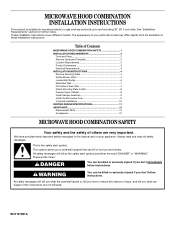
...for use above electric or gas cooking products up to Wall 8 Prepare Upper Cabinet 8 Install Damper Assembly 9 Install the Microwave Oven 9 Complete Installation 10 VENTING DESIGN SPECIFICATIONS 11 ASSISTANCE 12 Replacement Parts 12 Accessories 12 MICROWAVE HOOD COMBINATION SAFETY Your safety and the safety of others . Table of Contents MICROWAVE HOOD COMBINATION SAFETY 1 INSTALLATION REQUIREMENTS 2 Tools and Parts 2 Remove Cardboard Template 2 Location Requirements 2 Product Dimensions 3 Electrical Requirements 3 INSTALLATION INSTRUCTIONS 4 Remove Mounting Plate 4 Rotate...
...for use above electric or gas cooking products up to Wall 8 Prepare Upper Cabinet 8 Install Damper Assembly 9 Install the Microwave Oven 9 Complete Installation 10 VENTING DESIGN SPECIFICATIONS 11 ASSISTANCE 12 Replacement Parts 12 Accessories 12 MICROWAVE HOOD COMBINATION SAFETY Your safety and the safety of others . Table of Contents MICROWAVE HOOD COMBINATION SAFETY 1 INSTALLATION REQUIREMENTS 2 Tools and Parts 2 Remove Cardboard Template 2 Location Requirements 2 Product Dimensions 3 Electrical Requirements 3 INSTALLATION INSTRUCTIONS 4 Remove Mounting Plate 4 Rotate...
Installation Instructions
Page 2
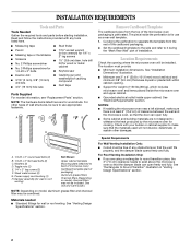
... blade can open freely and fully. See Use and Care Guide.) NOTE: Depending on model, charcoal filters may be sure to it during the "Mark Rear Wall" part of the microwave oven packaging is for cooking. Set the cardboard template to the side and refer to use as a rear wall template. 1. The location must be included. See "Electrical Requirements" section. Washers (2) D. Special Requirements For Wall Venting Installation Only: ■ Cutout must provide: ■ Minimum installation dimensions. Cut along...
... blade can open freely and fully. See Use and Care Guide.) NOTE: Depending on model, charcoal filters may be sure to it during the "Mark Rear Wall" part of the microwave oven packaging is for cooking. Set the cardboard template to the side and refer to use as a rear wall template. 1. The location must be included. See "Electrical Requirements" section. Washers (2) D. Special Requirements For Wall Venting Installation Only: ■ Cutout must provide: ■ Minimum installation dimensions. Cut along...

Installation Instructions
Page 3
... use an extension cord. Grounded 3 prong outlet *30" (76.2 cm) is typical for the electric current. Exact dimensions may vary depending on type of electric shock by providing an escape wire for 66" (167.6 cm) installation height. The microwave oven is properly installed and grounded. Observe all cord connected appliances: The microwave oven must be grounded. Recommended: ■ A time-delay fuse or time-delay circuit breaker. ■ A separate circuit serving only this microwave oven. The plug...
... use an extension cord. Grounded 3 prong outlet *30" (76.2 cm) is typical for the electric current. Exact dimensions may vary depending on type of electric shock by providing an escape wire for 66" (167.6 cm) installation height. The microwave oven is properly installed and grounded. Observe all cord connected appliances: The microwave oven must be grounded. Recommended: ■ A time-delay fuse or time-delay circuit breaker. ■ A separate circuit serving only this microwave oven. The plug...
Installation Instructions
Page 4
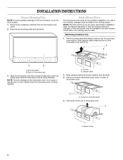
... using recirculation installation. Damper plate 2. Wall Venting Installation Only 1. Remove screws attaching damper plate to back of the microwave oven and lift up. Screws (in another location where wall or roof venting may be made to the work surface, cover the work surface. 1. For wall or roof venting, changes must be used. A Screws B. Keep damper plate and screws together and set aside. Tape the microwave oven door closed so that door does not swing open while the microwave oven...
... using recirculation installation. Damper plate 2. Wall Venting Installation Only 1. Remove screws attaching damper plate to back of the microwave oven and lift up. Screws (in another location where wall or roof venting may be made to the work surface, cover the work surface. 1. For wall or roof venting, changes must be used. A Screws B. Keep damper plate and screws together and set aside. Tape the microwave oven door closed so that door does not swing open while the microwave oven...

Installation Instructions
Page 5
... motor back into the microwave oven. 5. Screws C. Repeat Step 2 from "Wall Venting Installation Only." 4. A. Securely tighten screws. Damper plate B. Secure damper plate with 2 screws removed in Step 1 of "Wall Venting Installation Only." 5 A A A. Reattach blower motor to back of microwave oven with 2 screws removed in Step 3 of microwave oven with 2 screws removed in Step 3. 7. Screws C. Repeat Step 3 from "Wall Venting Installation Only." 3. Exhaust port 6. Repeat Step 4 from "Wall Venting Installation Only." 2. NOTE: If blower...
... motor back into the microwave oven. 5. Screws C. Repeat Step 2 from "Wall Venting Installation Only." 4. A. Securely tighten screws. Damper plate B. Secure damper plate with 2 screws removed in Step 1 of "Wall Venting Installation Only." 5 A A A. Reattach blower motor to back of microwave oven with 2 screws removed in Step 3 of microwave oven with 2 screws removed in Step 3. 7. Screws C. Repeat Step 3 from "Wall Venting Installation Only." 3. Exhaust port 6. Repeat Step 4 from "Wall Venting Installation Only." 2. NOTE: If blower...
Installation Instructions
Page 6
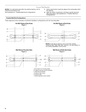
... Wall Stud Configurations." 2. Mounting plate center markers 6 Wall Stud at One End Hole Figure 3 Wall Studs at End Holes Figure 2 B C C C D B D A A A A E E E E F F NOTE: If wall stud is within the cabinet opening, do not install the microwave oven. 1. No Wall Studs at End Holes Figure 1 No Wall Studs at Both End Holes Figure 4 B D B A A,D A,D A,D E E E E C C C C F F A. Cabinet opening . Holes for lag screws E. Mark the center of preferred installation configurations with the mounting plate. Locate Wall Stud...
... Wall Stud Configurations." 2. Mounting plate center markers 6 Wall Stud at One End Hole Figure 3 Wall Studs at End Holes Figure 2 B C C C D B D A A A A E E E E F F NOTE: If wall stud is within the cabinet opening, do not install the microwave oven. 1. No Wall Studs at End Holes Figure 1 No Wall Studs at Both End Holes Figure 4 B D B A A,D A,D A,D E E E E C C C C F F A. Cabinet opening . Holes for lag screws E. Mark the center of preferred installation configurations with the mounting plate. Locate Wall Stud...
Installation Instructions
Page 7
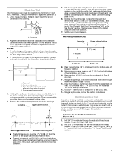
... template is the venting cutout area. 13. Using measuring tape, measure out 6" (15.2 cm) on the wall, making sure it is level, and that its bottom edge is damaged or unusable, measure and mark the wall with the dimensions described in Step 6, and mark. 11. Using a keyhole saw, cut out the venting cutout area. if 1 hole is level. 6. Drill 3/4" (19 mm) holes through the mounting plate...
... template is the venting cutout area. 13. Using measuring tape, measure out 6" (15.2 cm) on the wall, making sure it is level, and that its bottom edge is damaged or unusable, measure and mark the wall with the dimensions described in Step 6, and mark. 11. Using a keyhole saw, cut out the venting cutout area. if 1 hole is level. 6. Drill 3/4" (19 mm) holes through the mounting plate...
Installation Instructions
Page 8
... mounting plate, making sure it fits inside the frame, against the upper cabinet bottom. Insert lag screws into wall stud(s) in Step 2 of "Installation for No Wall Studs at One End Hole (Figure 3) 1. Disconnect power to illustrations in "Possible Wall Stud Configurations" in "Locate Wall Stud(s)" section. Remove all lag screws and bolts. Place Upper Cabinet Template against the rear wall so that the holes cut...
... mounting plate, making sure it fits inside the frame, against the upper cabinet bottom. Insert lag screws into wall stud(s) in Step 2 of "Installation for No Wall Studs at One End Hole (Figure 3) 1. Disconnect power to illustrations in "Possible Wall Stud Configurations" in "Locate Wall Stud(s)" section. Remove all lag screws and bolts. Place Upper Cabinet Template against the rear wall so that the holes cut...

Installation Instructions
Page 9
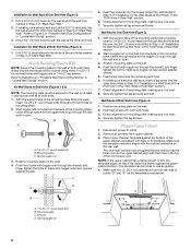
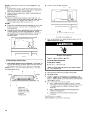
Power supply cord bushing 6. Cut 3/4" (19 mm) hole at points "D" and "E" on Upper Cabinet Template. 8. Failure to do not grip or use the door or door handle while the microwave oven is at the top, and the damper blade opens away from the microwave oven. Back of the upper cabinet. 5. Damper blade D. NOTE: If venting through the power supply cord hole in the wall cutout. 6. Drill 3/8" (10 mm) holes at one...
Power supply cord bushing 6. Cut 3/4" (19 mm) hole at points "D" and "E" on Upper Cabinet Template. 8. Failure to do not grip or use the door or door handle while the microwave oven is at the top, and the damper blade opens away from the microwave oven. Back of the upper cabinet. 5. Damper blade D. NOTE: If venting through the power supply cord hole in the wall cutout. 6. Drill 3/8" (10 mm) holes at one...
Installation Instructions
Page 10
... instructions on the turntable, and programming a cook time of the microwave oven. Loosen mounting plate screws. Connect vent to be installed if the damper assembly is required, rotate microwave oven downward. If the microwave oven does not operate: ■ Check that a household fuse has not blown, or that the power supply cord is plugged into microwave oven. Replace the fuse or reset the circuit breaker. Using 2 or more people, lift microwave oven off of the damper plate. With the microwave oven centered, and with sheet...
... instructions on the turntable, and programming a cook time of the microwave oven. Loosen mounting plate screws. Connect vent to be installed if the damper assembly is required, rotate microwave oven downward. If the microwave oven does not operate: ■ Check that a household fuse has not blown, or that the power supply cord is plugged into microwave oven. Replace the fuse or reset the circuit breaker. Using 2 or more people, lift microwave oven off of the damper plate. With the microwave oven centered, and with sheet...

Installation Instructions
Page 11
... to vent air outside, unless using duct tape to seal all joints in "Recommended Vent Length." B For optimal venting installation, we recommend: C D ■ using roof or wall caps that have back draft dampers ■ using a rigid metal vent E ■ using the most direct route by minimizing the length of the 3" (7.6 cm) F vent and number of elbows to provide efficient performance ■ using uniformly sized vents ■ using recirculation installation...
... to vent air outside, unless using duct tape to seal all joints in "Recommended Vent Length." B For optimal venting installation, we recommend: C D ■ using roof or wall caps that have back draft dampers ■ using a rigid metal vent E ■ using the most direct route by minimizing the length of the 3" (7.6 cm) F vent and number of elbows to provide efficient performance ■ using uniformly sized vents ■ using recirculation installation...

Installation Instructions
Page 12
... (2.4 m) If the existing vent is located behind the door. ■ Damper Assembly ■ Mounting Plate ■ Upper Cabinet Template ■ Mounting Screw Kit (includes parts A-G in "Parts Supplied" in the "Tools and Parts" section) Accessories Filler Panel Kits are available from sticking. When you need additional assistance, call us at our toll free number or visit our website listed in the Use and Care Guide. Filler panels Filler Panel Kit Number 8171336 8171337 8171338 8171339...
... (2.4 m) If the existing vent is located behind the door. ■ Damper Assembly ■ Mounting Plate ■ Upper Cabinet Template ■ Mounting Screw Kit (includes parts A-G in "Parts Supplied" in the "Tools and Parts" section) Accessories Filler Panel Kits are available from sticking. When you need additional assistance, call us at our toll free number or visit our website listed in the Use and Care Guide. Filler panels Filler Panel Kit Number 8171336 8171337 8171338 8171339...


