
Warranty Information
Page 1
... or province to use inconsistent with published user, operator or installation instructions. 2. YOUR SOLE AND EXCLUSIVE REMEDY UNDER THIS LIMITED WARRANTY SHALL BE PRODUCT REPAIR AS PROVIDED HEREIN. Proof of the product. 15. house wiring, fuses or water inlet hoses). 4. trim, decorative panels, flooring, cabinetry, islands, countertops, drywall, etc.) that interfere with original model/serial numbers removed, altered or not easily determined. Service or parts for service in materials or...
... or province to use inconsistent with published user, operator or installation instructions. 2. YOUR SOLE AND EXCLUSIVE REMEDY UNDER THIS LIMITED WARRANTY SHALL BE PRODUCT REPAIR AS PROVIDED HEREIN. Proof of the product. 15. house wiring, fuses or water inlet hoses). 4. trim, decorative panels, flooring, cabinetry, islands, countertops, drywall, etc.) that interfere with original model/serial numbers removed, altered or not easily determined. Service or parts for service in materials or...

Installation Guide
Page 2
.... TABLE OF CONTENTS RANGE HOOD SAFETY 2 INSTALLATION REQUIREMENTS 4 Tools and Parts 4 Location Requirements 4 Venting System 5 Electrical Requirements 6 INSTALLATION INSTRUCTIONS 7 RANGE HOOD USE 11 Range Hood Controls 11 RANGE HOOD CARE 11 Cleaning 11 WIRING DIAGRAM 12 ASSISTANCE OR SERVICE 13 In the U.S.A 13 In Canada 13 WARRANTY 14 TABLE DES MATIÈRES SÉCURITÉ DE LA HOTTE DE CUISINIÈRE 15 EXIGENCES D'INSTALLATION 17 Outillage et pièces 17 Exigences d'emplacement 17 Circuit d'évacuation...
.... TABLE OF CONTENTS RANGE HOOD SAFETY 2 INSTALLATION REQUIREMENTS 4 Tools and Parts 4 Location Requirements 4 Venting System 5 Electrical Requirements 6 INSTALLATION INSTRUCTIONS 7 RANGE HOOD USE 11 Range Hood Controls 11 RANGE HOOD CARE 11 Cleaning 11 WIRING DIAGRAM 12 ASSISTANCE OR SERVICE 13 In the U.S.A 13 In Canada 13 WARRANTY 14 TABLE DES MATIÈRES SÉCURITÉ DE LA HOTTE DE CUISINIÈRE 15 EXIGENCES D'INSTALLATION 17 Outillage et pièces 17 Exigences d'emplacement 17 Circuit d'évacuation...
Installation Guide
Page 4
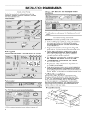
... for vented installations. Location Requirements IMPORTANT: Observe all parts are factory set for Manufactured Home Installation 1982 (Manufactured Home Sites, Communities and Setups) ANSI A225.1/NFPA 501A, or latest edition, or with wall or roof cap Duct tape Optional accessories Charcoal filter kit Part Number W10386873* Power cord kit Part Number W10355452* Stainless steel cleaner and polish Part Number 31462A* * For information on the left wall. ■■ Range hood location should be away from package. Consult the cooktop/range manufacturer installation instructions...
... for vented installations. Location Requirements IMPORTANT: Observe all parts are factory set for Manufactured Home Installation 1982 (Manufactured Home Sites, Communities and Setups) ANSI A225.1/NFPA 501A, or latest edition, or with wall or roof cap Duct tape Optional accessories Charcoal filter kit Part Number W10386873* Power cord kit Part Number W10355452* Stainless steel cleaner and polish Part Number 31462A* * For information on the left wall. ■■ Range hood location should be away from package. Consult the cooktop/range manufacturer installation instructions...

Installation Guide
Page 5
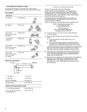
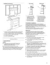
... cold air flow and a thermal break should be installed to minimize conduction of outside temperatures as possible to seal exterior wall or roof opening width D. 12" (30.5 cm) cabinet depth E. 36" (91.4 cm) base cabinet height Venting System Venting Methods NOTES: ■■ Flexible vent is not recommended. ■■ The length of vent system and number of the vent system. Roof cap with the range hood. ■■ Use caulking...
... cold air flow and a thermal break should be installed to minimize conduction of outside temperatures as possible to seal exterior wall or roof opening width D. 12" (30.5 cm) cabinet depth E. 36" (91.4 cm) base cabinet height Venting System Venting Methods NOTES: ■■ Flexible vent is not recommended. ■■ The length of vent system and number of the vent system. Roof cap with the range hood. ■■ Use caulking...
Installation Guide
Page 6
... the electrical installation is located inside the range hood on the model/serial/rating plate. wall cap 8 ft (2.4 m) straight System length = 5 ft (1.5 m) = 0 ft (0.0 m) = 8 ft (2.4 m) = 13 ft (3.9 m) Maximum Recommended Length 7" (17.8 cm) Round Vent 31/4" x 10" (8.3 x 25.4 cm) Rectangular Vent = 50 ft (15.2 m) = 35 ft (10.7 m) 6 Aluminum/copper connection must conform with local codes and industry accepted wiring practices. ■■ Wire sizes and connections must conform to the requirements of copper wire using special connectors...
... the electrical installation is located inside the range hood on the model/serial/rating plate. wall cap 8 ft (2.4 m) straight System length = 5 ft (1.5 m) = 0 ft (0.0 m) = 8 ft (2.4 m) = 13 ft (3.9 m) Maximum Recommended Length 7" (17.8 cm) Round Vent 31/4" x 10" (8.3 x 25.4 cm) Rectangular Vent = 50 ft (15.2 m) = 35 ft (10.7 m) 6 Aluminum/copper connection must conform with local codes and industry accepted wiring practices. ■■ Wire sizes and connections must conform to the requirements of copper wire using special connectors...

Installation Guide
Page 7
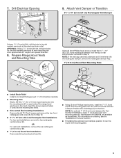
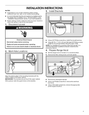
...) flat-head #2 Phillips screws, install the mounting brackets using the upper holes. Prepare Range Hood ■■ Set the range hood on its back on your model, determine which venting method to "Venting System" in death or electrical shock. 2. Replace all parts and panels before servicing. Disconnect power WARNING Electrical Shock Hazard Disconnect power before operating. Failure to a surface other than drywall, it is proper clearance within the ceiling or wall for the vent system. 1. With...
...) flat-head #2 Phillips screws, install the mounting brackets using the upper holes. Prepare Range Hood ■■ Set the range hood on its back on your model, determine which venting method to "Venting System" in death or electrical shock. 2. Replace all parts and panels before servicing. Disconnect power WARNING Electrical Shock Hazard Disconnect power before operating. Failure to a surface other than drywall, it is proper clearance within the ceiling or wall for the vent system. 1. With...
Installation Guide
Page 9
... an upward direction. 8. NOTE: If the wall cap used has a damper and it over the top or rear vent knockout removed in Step 8. Insert the screws approximately 2 turns into the mounting tab (F) on ordering, see the "Assistance or Service" section. ■■ If installing the optional round damper, position it interferes with the rectangular damper, remove the rectangular damper flap. 7" (17.8 cm) Round Vent Mounting Plate A C B ■■ Install Strain Relief Install a UL listed/CSA approved...
... an upward direction. 8. NOTE: If the wall cap used has a damper and it over the top or rear vent knockout removed in Step 8. Insert the screws approximately 2 turns into the mounting tab (F) on ordering, see the "Assistance or Service" section. ■■ If installing the optional round damper, position it interferes with the rectangular damper, remove the rectangular damper flap. 7" (17.8 cm) Round Vent Mounting Plate A C B ■■ Install Strain Relief Install a UL listed/CSA approved...

Installation Guide
Page 10
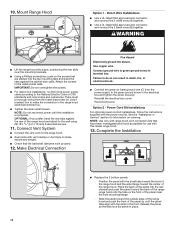
.... Connect Vent System ■■ Connect the vent work properly. 12. Make Electrical Connection Fire Hazard Electrically ground the blower. Use copper wire. Power Cord Kit Installations For optional power cord kit installations, follow the instructions supplied with vent clamps or duct tape to the National Electric Code or CSA standards and local codes and ordinances. IMPORTANT: Do not overtighten the screws. ■■ For direct wire installations, run the home power supply cable according to make the connection in place. 10 10. Mount Range Hood Option...
.... Connect Vent System ■■ Connect the vent work properly. 12. Make Electrical Connection Fire Hazard Electrically ground the blower. Use copper wire. Power Cord Kit Installations For optional power cord kit installations, follow the instructions supplied with vent clamps or duct tape to the National Electric Code or CSA standards and local codes and ordinances. IMPORTANT: Do not overtighten the screws. ■■ For direct wire installations, run the home power supply cable according to make the connection in place. 10 10. Mount Range Hood Option...

Installation Guide
Page 11
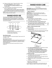
... filter. Grease filter 3. Operating the blower The blower buttons turn the blower off and control the blower speed and sound level for quiet operation. See the "Warranty" section for OFF. Grease filter latch C. Pull the filter latch toward the front of the range hood and pull down on the front edge of old charcoal filter. Range Hood Controls A B CD A. Disconnect the power and check the wiring connections. Screw B. For non-vented (recirculating) installations: Install a charcoal filter. ■■ Check the operation of the filter up to the stainless steel, do...
... filter. Grease filter 3. Operating the blower The blower buttons turn the blower off and control the blower speed and sound level for quiet operation. See the "Warranty" section for OFF. Grease filter latch C. Pull the filter latch toward the front of the range hood and pull down on the front edge of old charcoal filter. Range Hood Controls A B CD A. Disconnect the power and check the wiring connections. Screw B. For non-vented (recirculating) installations: Install a charcoal filter. ■■ Check the operation of the filter up to the stainless steel, do...

Installation Guide
Page 13
...; Accessory and repair parts sales. ■■ Specialized customer assistance (Spanish speaking, hearing impaired, limited vision, etc.). If you need replacement parts If you need service Please refer to the warranty page in your correspondence. To locate factory specified replacement parts in your nearest designated service center. In the U.S.A. Whirlpool designated service technicians are trained to fulfill the product warranty and provide after -warranty service anywhere in Canada. ■■ Features and specifications...
...; Accessory and repair parts sales. ■■ Specialized customer assistance (Spanish speaking, hearing impaired, limited vision, etc.). If you need replacement parts If you need service Please refer to the warranty page in your correspondence. To locate factory specified replacement parts in your nearest designated service center. In the U.S.A. Whirlpool designated service technicians are trained to fulfill the product warranty and provide after -warranty service anywhere in Canada. ■■ Features and specifications...

Installation Guide
Page 14
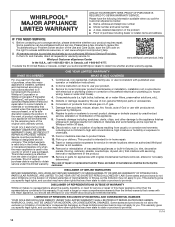
... to product failure. 12. Please have the following information available when you . Conversion of inaccessible appliances or built-in which it was purchased, or at its sole discretion replace the product. WHIRLPOOL® MAJOR APPLIANCE LIMITED WARRANTY ATTACH YOUR RECEIPT HERE. This limited warranty is used in the country in fixtures (i.e. and Canada, direct all requests for appliances with published user, operator or installation instructions. 2.
... to product failure. 12. Please have the following information available when you . Conversion of inaccessible appliances or built-in which it was purchased, or at its sole discretion replace the product. WHIRLPOOL® MAJOR APPLIANCE LIMITED WARRANTY ATTACH YOUR RECEIPT HERE. This limited warranty is used in the country in fixtures (i.e. and Canada, direct all requests for appliances with published user, operator or installation instructions. 2.
Use & Care Guide
Page 2
...'t follow instructions. TABLE OF CONTENTS RANGE HOOD SAFETY 2 INSTALLATION REQUIREMENTS 4 Tools and Parts 4 Location Requirements 4 Venting System 5 Electrical Requirements 6 INSTALLATION INSTRUCTIONS 7 RANGE HOOD USE 11 Range Hood Controls 11 RANGE HOOD CARE 11 Cleaning 11 WIRING DIAGRAM 12 ASSISTANCE OR SERVICE 13 In the U.S.A 13 In Canada 13 WARRANTY 14 TABLE DES MATIÈRES SÉCURITÉ DE LA HOTTE DE CUISINIÈRE 15 EXIGENCES D'INSTALLATION 17 Outillage et pièces 17 Exigences d'emplacement 17 Circuit d'é...
...'t follow instructions. TABLE OF CONTENTS RANGE HOOD SAFETY 2 INSTALLATION REQUIREMENTS 4 Tools and Parts 4 Location Requirements 4 Venting System 5 Electrical Requirements 6 INSTALLATION INSTRUCTIONS 7 RANGE HOOD USE 11 Range Hood Controls 11 RANGE HOOD CARE 11 Cleaning 11 WIRING DIAGRAM 12 ASSISTANCE OR SERVICE 13 In the U.S.A 13 In Canada 13 WARRANTY 14 TABLE DES MATIÈRES SÉCURITÉ DE LA HOTTE DE CUISINIÈRE 15 EXIGENCES D'INSTALLATION 17 Outillage et pièces 17 Exigences d'emplacement 17 Circuit d'é...

Use & Care Guide
Page 4
... with wall or roof cap Duct tape Optional accessories Charcoal filter kit Part Number W10386873* Power cord kit Part Number W10355452* Stainless steel cleaner and polish Part Number 31462A* * For information on ordering charcoal filters. The model/serial/rating plate is recommended for Manufactured Home Installation 1982 (Manufactured Home Sites, Communities and Setups) ANSI A225.1/NFPA 501A, or latest edition, or with local codes. Consult the cooktop/range manufacturer installation instructions before starting installation. INSTALLATION REQUIREMENTS Tools and Parts Gather...
... with wall or roof cap Duct tape Optional accessories Charcoal filter kit Part Number W10386873* Power cord kit Part Number W10355452* Stainless steel cleaner and polish Part Number 31462A* * For information on ordering charcoal filters. The model/serial/rating plate is recommended for Manufactured Home Installation 1982 (Manufactured Home Sites, Communities and Setups) ANSI A225.1/NFPA 501A, or latest edition, or with local codes. Consult the cooktop/range manufacturer installation instructions before starting installation. INSTALLATION REQUIREMENTS Tools and Parts Gather...
Use & Care Guide
Page 5
... 90° elbows. ■■ Make sure there is not recommended. Rigid metal vent is optional for specific requirements in your HVAC professional for this model. Use 31/4" x 10" (8.3 x 25.4 cm) rectangular with a maximum vent length of air movement. Wall cap with the range hood. ■■ Use caulking to seal exterior wall or roof opening width D. 12" (30.5 cm) cabinet depth E. 36" (91.4 cm) base cabinet height Venting System Venting Methods NOTES: ■...
... 90° elbows. ■■ Make sure there is not recommended. Rigid metal vent is optional for specific requirements in your HVAC professional for this model. Use 31/4" x 10" (8.3 x 25.4 cm) rectangular with a maximum vent length of air movement. Wall cap with the range hood. ■■ Use caulking to seal exterior wall or roof opening width D. 12" (30.5 cm) cabinet depth E. 36" (91.4 cm) base cabinet height Venting System Venting Methods NOTES: ■...

Use & Care Guide
Page 6
... Electrical Code, ANSI/NFPA 70 (latest edition) or CSA Standards C22. 1-94, Canadian Electrical Code, Part 1 and C22.2 No. 0-M91 (latest edition) and all local codes and ordinances. 2 ft (0.6 m) 1 - 90° elbow 1 - The model/serial/rating plate is located inside the range hood on the model/serial/rating plate. Connect a section of solid copper wire to 7" (17.8 cm) 90° elbow 5 ft (1.5 m) Example vent system 90˚ elbow 6 ft (1.8 m) Wall cap Electrical Requirements Observe all local codes...
... Electrical Code, ANSI/NFPA 70 (latest edition) or CSA Standards C22. 1-94, Canadian Electrical Code, Part 1 and C22.2 No. 0-M91 (latest edition) and all local codes and ordinances. 2 ft (0.6 m) 1 - 90° elbow 1 - The model/serial/rating plate is located inside the range hood on the model/serial/rating plate. Connect a section of solid copper wire to 7" (17.8 cm) 90° elbow 5 ft (1.5 m) Example vent system 90˚ elbow 6 ft (1.8 m) Wall cap Electrical Requirements Observe all local codes...
Use & Care Guide
Page 7
... a covered surface. ■■ Remove the filter, locking screw, and side panels. Replace all parts and panels before servicing. NOTE: For installations to "Venting System" in death or electrical shock. 2. Mark Hole Locations ■■ Using a #2 Phillips screwdriver, install the drywall anchors. ■■ Using #8-18 x 1" (4.2 x 25 mm) flat-head #2 Phillips screws, install the mounting brackets using the upper holes. Disconnect power WARNING Electrical Shock Hazard Disconnect power before operating. Prepare Range Hood ■■ Set the range hood...
... a covered surface. ■■ Remove the filter, locking screw, and side panels. Replace all parts and panels before servicing. NOTE: For installations to "Venting System" in death or electrical shock. 2. Mark Hole Locations ■■ Using a #2 Phillips screwdriver, install the drywall anchors. ■■ Using #8-18 x 1" (4.2 x 25 mm) flat-head #2 Phillips screws, install the mounting brackets using the upper holes. Disconnect power WARNING Electrical Shock Hazard Disconnect power before operating. Prepare Range Hood ■■ Set the range hood...
Use & Care Guide
Page 10
... power cord kit installations, follow the instructions supplied with vent clamps or duct tape to the green ground screw in the range hood electrical terminal box. ■■ Tighten the strain relief screws. Position the panel with this model range hood. 13. Attach the screws to the National Electric Code or CSA standards and local codes and ordinances. Connect ground wire to the range hood. ■■ Seal joints with the power cord kit. Connect Vent System ■■ Connect the vent work...
... power cord kit installations, follow the instructions supplied with vent clamps or duct tape to the green ground screw in the range hood electrical terminal box. ■■ Tighten the strain relief screws. Position the panel with this model range hood. 13. Attach the screws to the National Electric Code or CSA standards and local codes and ordinances. Connect ground wire to the range hood. ■■ Seal joints with the power cord kit. Connect Vent System ■■ Connect the vent work...
Use & Care Guide
Page 11
...-vented (recirculating) installations: Replace the metal filter with a soft, lint-free cloth. ■■ Glass cleaner to remove fingerprints. ■■ For stainless steel models, rub in the direction of the filter up to turn the blower on/off . Light On/Off button B. Blower On/Off and minimum speed button C. Press once for ON and again for service contact information. 11 Operating the blower The blower buttons turn the blower off and control the blower speed and sound level for quiet operation...
...-vented (recirculating) installations: Replace the metal filter with a soft, lint-free cloth. ■■ Glass cleaner to remove fingerprints. ■■ For stainless steel models, rub in the direction of the filter up to turn the blower on/off . Light On/Off button B. Blower On/Off and minimum speed button C. Press once for ON and again for service contact information. 11 Operating the blower The blower buttons turn the blower off and control the blower speed and sound level for quiet operation...
Use & Care Guide
Page 13
.... Whirlpool designated service technicians are trained to local dealers. ■■ Installation information. ■■ Use and maintenance procedures. ■■ Accessory and repair parts sales. ■■ Specialized customer assistance (Spanish speaking, hearing impaired, limited vision, etc.). In the U.S.A. If you need replacement parts If you need to order replacement parts, we recommend that you need service Please refer to the warranty page in Canada. ■■ Features and specifications...
.... Whirlpool designated service technicians are trained to local dealers. ■■ Installation information. ■■ Use and maintenance procedures. ■■ Accessory and repair parts sales. ■■ Specialized customer assistance (Spanish speaking, hearing impaired, limited vision, etc.). In the U.S.A. If you need replacement parts If you need to order replacement parts, we recommend that you need service Please refer to the warranty page in Canada. ■■ Features and specifications...
Use & Care Guide
Page 14
... installation, installation not in remote locations where an authorized Whirlpool servicer is provided exclusively by the use inconsistent with original model/serial numbers removed, altered or not easily determined. This warranty gives you specific legal rights, and you call the Customer eXperience Center: ■■ Name, address and telephone number ■■ Model number and serial number ■■ A clear, detailed description of the problem ■■ Proof of repair...
... installation, installation not in remote locations where an authorized Whirlpool servicer is provided exclusively by the use inconsistent with original model/serial numbers removed, altered or not easily determined. This warranty gives you specific legal rights, and you call the Customer eXperience Center: ■■ Name, address and telephone number ■■ Model number and serial number ■■ A clear, detailed description of the problem ■■ Proof of repair...


