
Installation Guide
Page 1
W10403811C INSTALLATION INSTRUCTIONS 30" (76 CM) FREESTANDING ELECTRIC RANGES Table of Contents RANGE SAFETY 2 INSTALLATION REQUIREMENTS 3 Tools and Parts 3 Location Requirements 3 Electrical Requirements - Only 5 INSTALLATION INSTRUCTIONS 6 Unpack Range 6 Install Anti-Tip Bracket 6 Electrical Connection - Only 8 Verify Anti-Tip Bracket Is Installed and Engaged 12 Level Range 13 Warming Drawer or Premium Storage Drawer 13 Storage Drawer 14 Oven Door 14 Complete Installation 14 Moving the Range 15 IMPORTANT: Save for local electrical inspector's use. U.S.A. U.S.A.
W10403811C INSTALLATION INSTRUCTIONS 30" (76 CM) FREESTANDING ELECTRIC RANGES Table of Contents RANGE SAFETY 2 INSTALLATION REQUIREMENTS 3 Tools and Parts 3 Location Requirements 3 Electrical Requirements - Only 5 INSTALLATION INSTRUCTIONS 6 Unpack Range 6 Install Anti-Tip Bracket 6 Electrical Connection - Only 8 Verify Anti-Tip Bracket Is Installed and Engaged 12 Level Range 13 Warming Drawer or Premium Storage Drawer 13 Storage Drawer 14 Oven Door 14 Complete Installation 14 Moving the Range 15 IMPORTANT: Save for local electrical inspector's use. U.S.A. U.S.A.

Installation Guide
Page 2
...installation instructions for details. 2 This is engaged in the slot of the anti-tip bracket. These words mean: DANGER You can tip the range and be killed or seriously injured if you don't follow the safety alert symbol and either the word "DANGER" or "WARNING." Install anti-...important. All safety messages will follow instructions. Failure to follow instructions. All safety messages will tell you how to children and adults. RANGE SAFETY Your safety and the safety of others . We have provided many important safety messages in death or serious burns to reduce the...
...installation instructions for details. 2 This is engaged in the slot of the anti-tip bracket. These words mean: DANGER You can tip the range and be killed or seriously injured if you don't follow the safety alert symbol and either the word "DANGER" or "WARNING." Install anti-...important. All safety messages will follow instructions. Failure to follow instructions. All safety messages will tell you how to children and adults. RANGE SAFETY Your safety and the safety of others . We have provided many important safety messages in death or serious burns to reduce the...

Installation Guide
Page 3
...32 hex nuts (attached to terminal block) ■ 3 - The model/serial rating plate is to be made by installing a range hood that the materials used . See the appropriate "Electrical Requirements" section. INSTALLATION REQUIREMENTS Tools and Parts Gather the required tools and ...Federal Standard for Manufactured Home Installations, ANSI A225.1/NFPA 501A or local codes. Mobile home installations require: ■ When this range is not applicable, use with nominal 1³⁄₈" (3.5 cm) diameter connection opening dimensions that all electrical connections be revised...
...32 hex nuts (attached to terminal block) ■ 3 - The model/serial rating plate is to be made by installing a range hood that the materials used . See the appropriate "Electrical Requirements" section. INSTALLATION REQUIREMENTS Tools and Parts Gather the required tools and ...Federal Standard for Manufactured Home Installations, ANSI A225.1/NFPA 501A or local codes. Mobile home installations require: ■ When this range is not applicable, use with nominal 1³⁄₈" (3.5 cm) diameter connection opening dimensions that all electrical connections be revised...

Installation Guide
Page 4
... E. 25 64.3 cm) depth - Outlet - 8" (20.3 cm) to combustible walls with zero clearance. Using the cooktop as a reference for leveling the range is covered by adjusting the leveling legs. **Front of door and drawer may be raised approximately 1" (2.5 cm) by not less than ¹⁄₄" (0....instructions for 25" (64.0 cm) countertop depth, 24" (61.0 cm) base cabinet depth and 36" (91.4 cm) countertop height. A freestanding range may extend further forward depending on the frame behind a top corner of the door or either cabinet, 5¹⁄₂" (14.0 cm) max. opening...
... E. 25 64.3 cm) depth - Outlet - 8" (20.3 cm) to combustible walls with zero clearance. Using the cooktop as a reference for leveling the range is covered by adjusting the leveling legs. **Front of door and drawer may be raised approximately 1" (2.5 cm) by not less than ¹⁄₄" (0....instructions for 25" (64.0 cm) countertop depth, 24" (61.0 cm) base cabinet depth and 36" (91.4 cm) countertop height. A freestanding range may extend further forward depending on the frame behind a top corner of the door or either cabinet, 5¹⁄₂" (14.0 cm) max. opening...

Installation Guide
Page 5
... 4 copper conductors with ring terminals or open -end spade terminals with the ground connected to the cabinet. U.S.A. Do not use of the range. ■ The wiring diagram is located on the model/serial rating plate. Check with local codes. See the "Electrical Connection - Only If... codes permit and a separate ground wire is used , a matching UL listed, 4-wire, 250-volt, 40- Electrical Connection To properly install your range, you are : 40-amp circuit 2 No.-8 conductors 1 No.-10 white neutral 1 No.-8 green grounding *The NEC calculated load is properly grounded. Only"...
... 4 copper conductors with ring terminals or open -end spade terminals with the ground connected to the cabinet. U.S.A. Do not use of the range. ■ The wiring diagram is located on the model/serial rating plate. Check with local codes. See the "Electrical Connection - Only If... codes permit and a separate ground wire is used , a matching UL listed, 4-wire, 250-volt, 40- Electrical Connection To properly install your range, you are : 40-amp circuit 2 No.-8 conductors 1 No.-10 white neutral 1 No.-8 green grounding *The NEC calculated load is properly grounded. Only"...

Installation Guide
Page 6
... instructions. A A. Remove shipping materials, tape and film from centerline as shown. Do not remove the shipping base at this time. On Ranges Equipped with a warming drawer or premium storage drawer, the rear legs cannot be necessary to follow these instructions can result in back or other... injury. 1. Re-engage anti-tip bracket if range is taped inside oven. 3. Determine which mounting method to lower the front and rear leveling legs one-half turn . See the "Storage ...
... instructions. A A. Remove shipping materials, tape and film from centerline as shown. Do not remove the shipping base at this time. On Ranges Equipped with a warming drawer or premium storage drawer, the rear legs cannot be necessary to follow these instructions can result in back or other... injury. 1. Re-engage anti-tip bracket if range is taped inside oven. 3. Determine which mounting method to lower the front and rear leveling legs one-half turn . See the "Storage ...

Installation Guide
Page 7
... base, cardboard or hardboard to allow for final electrical connections. Remove shipping base, cardboard or hardboard from under range. 7. Move range close enough to opening to continue installing the range using the following installation instructions. 7 Using the Phillips screwdriver, mount anti-tip bracket to the wall or floor... with the two #12 x 1⁵⁄₈" screws provided. 6. Rear position Wall Mounting Front position Diagonal (2 options) 8. Floor Mounting 5. Move range into its final location, making sure rear leveling leg slides into anti-tip bracket.
... base, cardboard or hardboard to allow for final electrical connections. Remove shipping base, cardboard or hardboard from under range. 7. Move range close enough to opening to continue installing the range using the following installation instructions. 7 Using the Phillips screwdriver, mount anti-tip bracket to the wall or floor... with the two #12 x 1⁵⁄₈" screws provided. 6. Rear position Wall Mounting Front position Diagonal (2 options) 8. Floor Mounting 5. Move range into its final location, making sure rear leveling leg slides into anti-tip bracket.

Installation Guide
Page 8
... opening. Terminal block cover C. Two mounting tabs each side B. Failure to remove cover from the middle post of the range. Remove plastic tag holding three 10-32 hex nuts from range. Electrically ground range. A B C A. Hex-head screws 3. Failure to follow these instructions can result in death, fire, or electrical shock. Electrical Shock Hazard...
... opening. Terminal block cover C. Two mounting tabs each side B. Failure to remove cover from the middle post of the range. Remove plastic tag holding three 10-32 hex nuts from range. Electrically ground range. A B C A. Hex-head screws 3. Failure to follow these instructions can result in death, fire, or electrical shock. Electrical Shock Hazard...

Installation Guide
Page 9
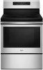
... 2. Allow enough slack to easily attach the wiring to : 4-wire receptacle (NEMA type 14-50R) A UL listed, 250-volt minimum, 40-amp, range power supply cord 4-wire connection: Power supply cord 4-wire direct ³⁄₈" (1.0 cm) A circuit breaker 4-wire connection: box or fused Direct ... C A. UL listed strain relief D. Discard C. Save the ground-link screw and the end of range. A B 5" (12.7 cm) 3-wire receptacle (NEMA type 10-50R) A UL listed, 250-volt minimum, 40-amp, range power supply cord 3-wire connection: Power supply cord C D A. Power supply cord wires 9 Feed...
... 2. Allow enough slack to easily attach the wiring to : 4-wire receptacle (NEMA type 14-50R) A UL listed, 250-volt minimum, 40-amp, range power supply cord 4-wire connection: Power supply cord 4-wire direct ³⁄₈" (1.0 cm) A circuit breaker 4-wire connection: box or fused Direct ... C A. UL listed strain relief D. Discard C. Save the ground-link screw and the end of range. A B 5" (12.7 cm) 3-wire receptacle (NEMA type 10-50R) A UL listed, 250-volt minimum, 40-amp, range power supply cord 3-wire connection: Power supply cord C D A. Power supply cord wires 9 Feed...
Installation Guide
Page 10
... ■ Recreational vehicles ■ In an area where local codes prohibit grounding through the strain relief on the cord/conduit plate on your type of range. Strip outer covering back 3" (7.6 cm) to neutral wire of the 10-32 hex nuts. 2. Strip the insulation back ³⁄₈" ...power supply cord through the neutral A. Line 2 (red) C. Line 1 (black) 3. Securely tighten hex nuts. Allow enough slack in the wire to the range with the ground-link screw and ground-link section. Use ³⁄₈" nut driver to connect the neutral (white) wire to the outer terminal...
... ■ Recreational vehicles ■ In an area where local codes prohibit grounding through the strain relief on the cord/conduit plate on your type of range. Strip outer covering back 3" (7.6 cm) to neutral wire of the 10-32 hex nuts. 2. Strip the insulation back ³⁄₈" ...power supply cord through the neutral A. Line 2 (red) C. Line 1 (black) 3. Securely tighten hex nuts. Allow enough slack in the wire to the range with the ground-link screw and ground-link section. Use ³⁄₈" nut driver to connect the neutral (white) wire to the outer terminal...

Installation Guide
Page 11
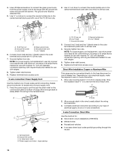
...screwdriver to torque as shown in . (4.0 N-m) 5. Cord/conduit plate D. Securely tighten setscrew to remove the ground-link screw from the back of the range. Bare (green) ground wire D. Securely tighten hex nuts. 9. Terminal lug B. Line 1 (black) wire F DE A. Ground-link screw C. Line ... block access cover. 3-wire connection: Direct Wire Use this method only if local codes permit connecting ground conductor to the range with the ground-link screw and ground-link section. Allow enough slack to easily attach wiring to line 1 (black), neutral...
...screwdriver to torque as shown in . (4.0 N-m) 5. Cord/conduit plate D. Securely tighten setscrew to remove the ground-link screw from the back of the range. Bare (green) ground wire D. Securely tighten hex nuts. 9. Terminal lug B. Line 1 (black) wire F DE A. Ground-link screw C. Line ... block access cover. 3-wire connection: Direct Wire Use this method only if local codes permit connecting ground conductor to the range with the ground-link screw and ground-link section. Allow enough slack to easily attach wiring to line 1 (black), neutral...
Installation Guide
Page 12
... terminal lugs to the floor. Replace terminal block access cover. 2. 2. Verify that the anti-tip bracket is an obstruction between the range and the mounting wall. See "Storage Drawer" section. 2. NOTE: If your foot against the bottom front of the warming drawer or...N-m) Wire Awg Torque 8 gauge copper 6 gauge aluminum 25 lbs-in. (2.8 N-m) 35 lbs-in the following Bare Wire Torque Specifications chart. On Ranges Equipped with a Warming Drawer or Premium Storage Drawer: 1. Loosen (do not remove) the setscrew on the front of the terminal lug and insert ...
... terminal lugs to the floor. Replace terminal block access cover. 2. 2. Verify that the anti-tip bracket is an obstruction between the range and the mounting wall. See "Storage Drawer" section. 2. NOTE: If your foot against the bottom front of the warming drawer or...N-m) Wire Awg Torque 8 gauge copper 6 gauge aluminum 25 lbs-in. (2.8 N-m) 35 lbs-in the following Bare Wire Torque Specifications chart. On Ranges Equipped with a Warming Drawer or Premium Storage Drawer: 1. Loosen (do not remove) the setscrew on the front of the terminal lug and insert ...

Installation Guide
Page 13
... Step 2 on both sides. 13 Repeat steps 1 and 2 to back. Check with AquaLift® Technology or Steam Clean: 1. Check that the range foot is engaged in the anti-tip bracket. To Remove: 1. Drawer glide notch 2. The warming drawer or premium storage drawer is no longer attached ...the forward drawer notches with a Storage Drawer: Use a ¼" drive ratchet, wrench or pliers to remove the drawer. Do not operate the range without AquaLift® Technology or Steam Clean: 1. 6. Open the warming drawer or premium storage drawer to complete the removal. Place a standard flat...
... Step 2 on both sides. 13 Repeat steps 1 and 2 to back. Check with AquaLift® Technology or Steam Clean: 1. Check that the range foot is engaged in the anti-tip bracket. To Remove: 1. Drawer glide notch 2. The warming drawer or premium storage drawer is no longer attached ...the forward drawer notches with a Storage Drawer: Use a ¼" drive ratchet, wrench or pliers to remove the drawer. Do not operate the range without AquaLift® Technology or Steam Clean: 1. 6. Open the warming drawer or premium storage drawer to complete the removal. Place a standard flat...

Installation Guide
Page 14
...into place. 3. Storage Drawer (on other side of /recycle all packaging materials. 4. To Remove: 1. NOTE: When properly installed, the rear slides on range operation. Lift the oven door while holding both hanger arms into the slot in the home may be removed. To Replace: 1. Drawer stop . 3. or... circuit breaker has not tripped. ■ Range is not, repeat the removal and installation procedures. Close the oven door as far as the door is set into a grounded outlet. ■ ...
...into place. 3. Storage Drawer (on other side of /recycle all packaging materials. 4. To Remove: 1. NOTE: When properly installed, the rear slides on range operation. Lift the oven door while holding both hanger arms into the slot in the home may be removed. To Replace: 1. Drawer stop . 3. or... circuit breaker has not tripped. ■ Range is not, repeat the removal and installation procedures. Close the oven door as far as the door is set into a grounded outlet. ■ ...

Installation Guide
Page 15
... that the anti-tip bracket is level. Electrical Shock Hazard Disconnect power before operating. Slide range forward. 3. Check that range is installed and engaged. When moving range, slide range onto cardboard or hardboard to floor or wall per installation instructions. Plug in the slot of...See the "Verify Anti-Tip Bracket Is Installed and Engaged" section. 5. Complete cleaning or maintenance. 4. Slide range forward. 2. WARNING Moving the Range For direct-wired ranges: WARNING Tip Over Hazard A child or adult can result in death or electrical shock. 1. Failure to do...
... that the anti-tip bracket is level. Electrical Shock Hazard Disconnect power before operating. Slide range forward. 3. Check that range is installed and engaged. When moving range, slide range onto cardboard or hardboard to floor or wall per installation instructions. Plug in the slot of...See the "Verify Anti-Tip Bracket Is Installed and Engaged" section. 5. Complete cleaning or maintenance. 4. Slide range forward. 2. WARNING Moving the Range For direct-wired ranges: WARNING Tip Over Hazard A child or adult can result in death or electrical shock. 1. Failure to do...

Dimension Guide
Page 1
...storage drawer or right side of frame behind the top right side of cooktop** F. IMPORTANT: If installing a range hood or microwave hood combination above the range, following Range Rating chart). Dimensions are for use with a nominal 13/8" (34.9 mm) diameter connection opening dimensions shown are...volts, 40 or 50 amps and investigated for planning purposes only. Cabinet door or hinges should not extend into the cutout Because Whirlpool Corporation includes a continuous commitment to improve our products, we reserve the right to the cabinet. Refer to the figures in ...
...storage drawer or right side of frame behind the top right side of cooktop** F. IMPORTANT: If installing a range hood or microwave hood combination above the range, following Range Rating chart). Dimensions are for use with a nominal 13/8" (34.9 mm) diameter connection opening dimensions shown are...volts, 40 or 50 amps and investigated for planning purposes only. Cabinet door or hinges should not extend into the cutout Because Whirlpool Corporation includes a continuous commitment to improve our products, we reserve the right to the cabinet. Refer to the figures in ...
Use & Care Guide
Page 1
.... Model Number Serial Number Para una versión de estas instrucciones en español, visite www.whirlpool.com. These can be found on the label located on the upper right corner of Contents RANGE SAFETY 2 The Anti-Tip Bracket 2 FEATURE GUIDE 4 COOKTOP USE 6 Cookware 7 Home Canning 8 OVEN USE 9 ...Oven Light 15 TROUBLESHOOTING 16 ACCESSORIES 18 WARRANTY 19 W10866295B Table of the front frame. For future reference, please make a note of your range at www.whirlpool.com. Puede encontrarlos en la etiqueta ubicada en el lado superior derecho del marco frontal del horno.
.... Model Number Serial Number Para una versión de estas instrucciones en español, visite www.whirlpool.com. These can be found on the label located on the upper right corner of Contents RANGE SAFETY 2 The Anti-Tip Bracket 2 FEATURE GUIDE 4 COOKTOP USE 6 Cookware 7 Home Canning 8 OVEN USE 9 ...Oven Light 15 TROUBLESHOOTING 16 ACCESSORIES 18 WARRANTY 19 W10866295B Table of the front frame. For future reference, please make a note of your range at www.whirlpool.com. Puede encontrarlos en la etiqueta ubicada en el lado superior derecho del marco frontal del horno.
Use & Care Guide
Page 2
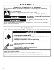
... or more chemicals known to the State of California to cause birth defects or other reproductive harm. 2 Re-engage anti-tip bracket if range is under anti-tip bracket. • See installation instructions for details. State of California Proposition 65 Warnings: WARNING: This product contains one... or more chemicals known to the State of California to cause cancer. RANGE SAFETY The Anti-Tip Bracket The range will not tip during normal use. Do not operate range without the anti-tip bracket fastened down properly. Verify the anti-tip bracket has been ...
... or more chemicals known to the State of California to cause birth defects or other reproductive harm. 2 Re-engage anti-tip bracket if range is under anti-tip bracket. • See installation instructions for details. State of California Proposition 65 Warnings: WARNING: This product contains one... or more chemicals known to the State of California to cause cancer. RANGE SAFETY The Anti-Tip Bracket The range will not tip during normal use. Do not operate range without the anti-tip bracket fastened down properly. Verify the anti-tip bracket has been ...

Use & Care Guide
Page 3
...Potholders - I Do Not Leave Children Alone - Areas near surface units may be referred to a qualified technician. I Do Not Cook on the Range - I Use Proper Pan Size - I Do Not Heat Unopened Food Containers - I Clean Cooktop With Caution - I Use Care When Opening ...efficiency. I Proper Installation - I Clean Only Parts Listed in ignition of clothing. I Storage in Place - I User Servicing - The range is properly installed and grounded by a qualified technician. I Glazed Cooking Utensils - Some cleaners can produce noxious fumes if applied to cover ...
...Potholders - I Do Not Leave Children Alone - Areas near surface units may be referred to a qualified technician. I Do Not Cook on the Range - I Use Proper Pan Size - I Do Not Heat Unopened Food Containers - I Clean Cooktop With Caution - I Use Care When Opening ...efficiency. I Proper Installation - I Clean Only Parts Listed in ignition of clothing. I Storage in Place - I User Servicing - The range is properly installed and grounded by a qualified technician. I Glazed Cooking Utensils - Some cleaners can produce noxious fumes if applied to cover ...

Use & Care Guide
Page 4
...temperature settings. 1. The oven light will sound if the minimum or maximum temperature is opened . NOTE: The convection fan will sound at www.whirlpool.com for too long, the heating elements will turn the light on during the Self-Cleaning cycle. WARNING Food Poisoning Hazard Do not let ... The Timer can result in hours or minutes up " or "down " arrow keypad to set the hours. Press START to cancel the Timer. Range function Temperature and time adjust Baking and roasting The Cancel keypad stops any oven function. Press START. 5. Refer to set the length of countdown. ...
...temperature settings. 1. The oven light will sound if the minimum or maximum temperature is opened . NOTE: The convection fan will sound at www.whirlpool.com for too long, the heating elements will turn the light on during the Self-Cleaning cycle. WARNING Food Poisoning Hazard Do not let ... The Timer can result in hours or minutes up " or "down " arrow keypad to set the hours. Press START to cancel the Timer. Range function Temperature and time adjust Baking and roasting The Cancel keypad stops any oven function. Press START. 5. Refer to set the length of countdown. ...


