
Instruction Sheet
Page 1
... are required. 3. Replace all parts and panels before servicing. Take the switch removed from the range and measure the shaft length from range and determine the wattage rating at 240 volts(check electrical rating stamped on next page) It will cause premature failure due to do so can result in kit. INSTRUCTION SHEET for 242905 Canning Surface Element Kit NOTE: Approved for use , beginning with Whirlpool RDE series and later electric range models, to replace...
... are required. 3. Replace all parts and panels before servicing. Take the switch removed from the range and measure the shaft length from range and determine the wattage rating at 240 volts(check electrical rating stamped on next page) It will cause premature failure due to do so can result in kit. INSTRUCTION SHEET for 242905 Canning Surface Element Kit NOTE: Approved for use , beginning with Whirlpool RDE series and later electric range models, to replace...

Dimension Guide
Page 1
....2 cm) I . L. Cabinet door or hinges should be level after installation. 30" (76.2 cm) Freestanding Gas Range PRODUCT MODEL NUMBERS PRODUCT DIMENSIONS WFG540H0A WFG540H0E WFG710H0A WFG714HLA WFG715H0E WFG720H0A WFG745H0F WFG770H0F Type of Gas Natural Gas: ■■ This range is factory set for use with a manual shutoff valve. Do not use TEFLON®† tape. Follow the instructions in the system. G H F ■■ Must include a shutoff valve: The supply line must be located in * C. 467...
....2 cm) I . L. Cabinet door or hinges should be level after installation. 30" (76.2 cm) Freestanding Gas Range PRODUCT MODEL NUMBERS PRODUCT DIMENSIONS WFG540H0A WFG540H0E WFG710H0A WFG714HLA WFG715H0E WFG720H0A WFG745H0F WFG770H0F Type of Gas Natural Gas: ■■ This range is factory set for use with a manual shutoff valve. Do not use TEFLON®† tape. Follow the instructions in the system. G H F ■■ Must include a shutoff valve: The supply line must be located in * C. 467...

Installation Guide
Page 3
... engaged: • Slide range forward. • Look for details. Thickness of flooring may require longer screws to anchor bracket to floor or wall per installation instructions. Install anti-tip bracket to floor. Check existing gas supply and electrical supply. Failure to follow the instructions provided with any tools listed Check that all parts are included. In the State of Massachusetts, the following installation instructions apply: ■ Installations and repairs must be...
... engaged: • Slide range forward. • Look for details. Thickness of flooring may require longer screws to anchor bracket to floor or wall per installation instructions. Install anti-tip bracket to floor. Check existing gas supply and electrical supply. Failure to follow the instructions provided with any tools listed Check that all parts are included. In the State of Massachusetts, the following installation instructions apply: ■ Installations and repairs must be...

Installation Guide
Page 4
... floor anti-tip bracket must be level after installation. Model/serial rating plate (located on the oven frame behind the top right side of door and drawer may extend farther forward, depending on styling. 4 Product Dimensions ■ Recessed installations must provide complete enclosure of the sides and rear of this document. In Canada, the installation of the range. ■ All openings in the wall or floor where range is required...
... floor anti-tip bracket must be level after installation. Model/serial rating plate (located on the oven frame behind the top right side of door and drawer may extend farther forward, depending on styling. 4 Product Dimensions ■ Recessed installations must provide complete enclosure of the sides and rear of this document. In Canada, the installation of the range. ■ All openings in the wall or floor where range is required...
Installation Guide
Page 5
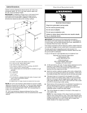
... normal operating nature of electronic gas ranges. ■ The wiring diagram is not required to countertop B. 13" (33 cm) max. Check that the outlet provides 120-volt power and is correctly grounded. ■ This gas range is located on a GFCI-protected circuit. Electrical Requirements WARNING B C A E K G F J L H I . 2" (5.1 cm) J. 4¹⁄₂" (11.4 cm) K. 3" (7.6 cm) min. If the metal chassis of the range is also recommended. Cabinet Dimensions Cabinet opening dimensions...
... normal operating nature of electronic gas ranges. ■ The wiring diagram is not required to countertop B. 13" (33 cm) max. Check that the outlet provides 120-volt power and is correctly grounded. ■ This gas range is located on a GFCI-protected circuit. Electrical Requirements WARNING B C A E K G F J L H I . 2" (5.1 cm) J. 4¹⁄₂" (11.4 cm) K. 3" (7.6 cm) min. If the metal chassis of the range is also recommended. Cabinet Dimensions Cabinet opening dimensions...

Installation Guide
Page 6
... of local codes, installation must conform with the range connection. All strains must be used in the same room but external to the range opening and closing. B A C A. The model/serial rating plate located on the oven frame behind the top right side of gas available, check with Natural gas. LP gas conversion: Conversion must be removed from the gas specified on or shutting off valve. With LP gas, piping or tubing size can be...
... of local codes, installation must conform with the range connection. All strains must be used in the same room but external to the range opening and closing. B A C A. The model/serial rating plate located on the oven frame behind the top right side of gas available, check with Natural gas. LP gas conversion: Conversion must be removed from the gas specified on or shutting off valve. With LP gas, piping or tubing size can be...

Installation Guide
Page 7
... leveling legs one -half turn . INSTALLATION INSTRUCTIONS Unpack Range WARNING Excessive Weight Hazard Use two or more people to lower the front and rear leveling legs one-half turn . Use a wrench or pliers to adjust the rear legs from outside the range. Remove oven racks and parts package from range. 2. Rear leveling leg C. Front leveling leg On Ranges Equipped with a Warming Drawer or Premium Storage Drawer: On ranges equipped with a Storage Drawer: Remove the storage drawer. Line pressure testing at test pressures...
... leveling legs one -half turn . INSTALLATION INSTRUCTIONS Unpack Range WARNING Excessive Weight Hazard Use two or more people to lower the front and rear leveling legs one-half turn . Use a wrench or pliers to adjust the rear legs from outside the range. Remove oven racks and parts package from range. 2. Rear leveling leg C. Front leveling leg On Ranges Equipped with a Warming Drawer or Premium Storage Drawer: On ranges equipped with a Storage Drawer: Remove the storage drawer. Line pressure testing at test pressures...

Installation Guide
Page 8
... anti-tip bracket. See the following installation instructions. Install Anti-Tip Bracket WARNING Wall Mounting Tip Over Hazard A child or adult can tip the range and be installed on either the left side or right side of the cutout. Install anti-tip bracket to the floor. 3. Slide range back so rear range foot is moved. Re-engage anti-tip bracket if range is engaged in death or serious burns to the supply line type, size and location. 1. Do not operate range without anti-tip bracket installed...
... anti-tip bracket. See the following installation instructions. Install Anti-Tip Bracket WARNING Wall Mounting Tip Over Hazard A child or adult can tip the range and be installed on either the left side or right side of the cutout. Install anti-tip bracket to the floor. 3. Slide range back so rear range foot is moved. Re-engage anti-tip bracket if range is engaged in death or serious burns to the supply line type, size and location. 1. Do not operate range without anti-tip bracket installed...

Installation Guide
Page 9
... illustration). 2. Manual gas shutoff valve G. ½" or ¾" gas pipe H. Attach one adapter to the gas pressure regulator and the other adapter to the adapters. Open valve 3. Correct any leak found. 4. Burner caps should be level when properly positioned. If burner caps are not properly positioned, surface burners will not light. Burner grate A. Use pipe-joint compound. H. Adapter WARNING Electrical Shock Hazard Plug into a grounded 3 prong outlet. 6. Plug into a grounded...
... illustration). 2. Manual gas shutoff valve G. ½" or ¾" gas pipe H. Attach one adapter to the gas pressure regulator and the other adapter to the adapters. Open valve 3. Correct any leak found. 4. Burner caps should be level when properly positioned. If burner caps are not properly positioned, surface burners will not light. Burner grate A. Use pipe-joint compound. H. Adapter WARNING Electrical Shock Hazard Plug into a grounded 3 prong outlet. 6. Plug into a grounded...

Installation Guide
Page 10
... the control panel as indicated in the illustration. 5. Repeat steps 1 and 2 to adjust leveling legs up or down until rear leveling leg is held securely in the bracket. If you need assistance or service, refer to the "Assistance or Service" section of the Use and Care Guide, or the cover or "Warranty" section of the User Instructions, to grasp the range higher than 2" (5.1 cm) from the anti-tip bracket. 3. Push range back...
... the control panel as indicated in the illustration. 5. Repeat steps 1 and 2 to adjust leveling legs up or down until rear leveling leg is held securely in the bracket. If you need assistance or service, refer to the "Assistance or Service" section of the Use and Care Guide, or the cover or "Warranty" section of the User Instructions, to grasp the range higher than 2" (5.1 cm) from the anti-tip bracket. 3. Push range back...

Installation Guide
Page 11
... The oven bake burner should light within 4 seconds. Adjust Oven Bake Burner Flame (if needed) 1. On models with a warming drawer, remove access cover plate (1 screw) located at the rear of the oven controls. B C A. No yellow tips, blowing or lifting of standing pilots. Pliers 11 Electronic Ignition System Initial lighting and gas flame adjustments Cooktop and oven burners use electronic igniters in place of flame should occur. When the cooktop control knob is turned to "Off" and contact your dealer or authorized service company for proper operation of the oven bottom...
... The oven bake burner should light within 4 seconds. Adjust Oven Bake Burner Flame (if needed) 1. On models with a warming drawer, remove access cover plate (1 screw) located at the rear of the oven controls. B C A. No yellow tips, blowing or lifting of standing pilots. Pliers 11 Electronic Ignition System Initial lighting and gas flame adjustments Cooktop and oven burners use electronic igniters in place of flame should occur. When the cooktop control knob is turned to "Off" and contact your dealer or authorized service company for proper operation of the oven bottom...

Installation Guide
Page 12
... the START pad. Refer to complete the removal. Drawer alignment tab B. Open the warming drawer or premium storage drawer to be adjusted: 1. Close the oven door. 2. This flame should be present. A A B A. Tighten locking screw. Adjust Oven Broil Burner Flame (if needed . 3. Align the forward drawer notches with an outer mantle of dark blue, and should have a ½" (1.3 cm) long inner cone of flame should light within 8 seconds. Check Operation of the oven controls. Using...
... the START pad. Refer to complete the removal. Drawer alignment tab B. Open the warming drawer or premium storage drawer to be adjusted: 1. Close the oven door. 2. This flame should be present. A A B A. Tighten locking screw. Adjust Oven Broil Burner Flame (if needed . 3. Align the forward drawer notches with an outer mantle of dark blue, and should have a ½" (1.3 cm) long inner cone of flame should light within 8 seconds. Check Operation of the oven controls. Using...

Installation Guide
Page 13
...; Electrical supply is plugged into place. 3. Open oven door all of the Use and Care Guide or User Instructions. 6. You should hear a "click" as outlined above. ■ If the gas supply line shutoff valve is off the range and check that the drawer stop notch is an extra part, go back through the steps to remove the oven door. Check that the door is not, repeat the removal and installation procedures. Turn on some models) The...
...; Electrical supply is plugged into place. 3. Open oven door all of the Use and Care Guide or User Instructions. 6. You should hear a "click" as outlined above. ■ If the gas supply line shutoff valve is off the range and check that the drawer stop notch is an extra part, go back through the steps to remove the oven door. Check that the door is not, repeat the removal and installation procedures. Turn on some models) The...

Installation Guide
Page 14
...Do not remove the gas pressure regulator. 14 Install a shut-off valve. If connected to floor or wall per installation instructions. Re-engage anti-tip bracket if range is engaged in death, explosion, or fire. To range B. Gas supply line 2. Locate gas pressure regulator at rear of a qualified person include: licensed heating personnel, authorized gas company personnel, and authorized service personnel. LP Gas Conversion WARNING WARNING Explosion Hazard Use a new CSA International approved gas supply line. Unplug range or disconnect power. Install anti-tip bracket to...
...Do not remove the gas pressure regulator. 14 Install a shut-off valve. If connected to floor or wall per installation instructions. Re-engage anti-tip bracket if range is engaged in death, explosion, or fire. To range B. Gas supply line 2. Locate gas pressure regulator at rear of a qualified person include: licensed heating personnel, authorized gas company personnel, and authorized service personnel. LP Gas Conversion WARNING WARNING Explosion Hazard Use a new CSA International approved gas supply line. Unplug range or disconnect power. Install anti-tip bracket to...

Installation Guide
Page 15
... for the remaining burners. Place Natural gas orifice spuds in the oven. Igniter electrode C. Side view before A 3. Gas pressure regulator cap 5. Replace plastic cover over the gas pressure regulator cap and reinstall on the oven frame behind the top right side of the oven door for each burner location. 5. Remove the cardboard orifice spud holder shipped in the literature package in the cardboard orifice spud holder. 6. LP groove Refer to the Model Number and Serial Number Plate located on regulator so that...
... for the remaining burners. Place Natural gas orifice spuds in the oven. Igniter electrode C. Side view before A 3. Gas pressure regulator cap 5. Replace plastic cover over the gas pressure regulator cap and reinstall on the oven frame behind the top right side of the oven door for each burner location. 5. Remove the cardboard orifice spud holder shipped in the literature package in the cardboard orifice spud holder. 6. LP groove Refer to the Model Number and Serial Number Plate located on regulator so that...

Installation Guide
Page 16
.... Orifice hood 3. Install the LP gas broiler burner orifice hood, turning it clockwise until snug. Replace the oven racks. A. See the "Oven Door" section. 9. Lift the back of the bake burner off the oven orifice, and set it aside on front of the bake burner into the oven. 11. Install the LP gas bake burner orifice spud, turning it clockwise until snug. A x.xx A. Place the broil burner on the broil burner orifice hood and insert the broil burner ceramic igniter in the hole in the back of the oven while changing...
.... Orifice hood 3. Install the LP gas broiler burner orifice hood, turning it clockwise until snug. Replace the oven racks. A. See the "Oven Door" section. 9. Lift the back of the bake burner off the oven orifice, and set it aside on front of the bake burner into the oven. 11. Install the LP gas bake burner orifice spud, turning it clockwise until snug. A x.xx A. Place the broil burner on the broil burner orifice hood and insert the broil burner ceramic igniter in the hole in the back of the oven while changing...

Installation Guide
Page 17
... C. Natural Gas Conversion WARNING To Convert Gas Pressure Regulator (LP Gas to Natural Gas) 1. NOTE: Do not remove the spring beneath the cap. Turn the manual shutoff valve to ½" (1.3 cm) long. Gas supply line 2. Replace plastic cover over the gas pressure regulator cap and reinstall on regulator so that have to hold the orifice spud holder in the slot of the screws through the range cooktop to adjust the "LO" setting for proper cooktop, bake and broil burner flame is very important. Complete Installation (Natural Gas...
... C. Natural Gas Conversion WARNING To Convert Gas Pressure Regulator (LP Gas to Natural Gas) 1. NOTE: Do not remove the spring beneath the cap. Turn the manual shutoff valve to ½" (1.3 cm) long. Gas supply line 2. Replace plastic cover over the gas pressure regulator cap and reinstall on regulator so that have to hold the orifice spud holder in the slot of the screws through the range cooktop to adjust the "LO" setting for proper cooktop, bake and broil burner flame is very important. Complete Installation (Natural Gas...

Installation Guide
Page 18
... oven. Replace the "56" spud with package containing literature. 6. Orifice spud 18 Set gas orifice spud aside. Screw D. Place LP gas orifice spuds in the nut driver while changing it aside on the oven frame behind the top right side of the oven door for proper sizing of the bake burner to the side to the Model Number and Serial Number Plate located on a covered surface. A. Lift the back of the oven bottom. 3. Bake burner 6. A A. Orifice spud B. Natural Gas Orifice Spud Chart Burner Rating Color Size ID Number 18,000 BTU...
... oven. Replace the "56" spud with package containing literature. 6. Orifice spud 18 Set gas orifice spud aside. Screw D. Place LP gas orifice spuds in the nut driver while changing it aside on the oven frame behind the top right side of the oven door for proper sizing of the bake burner to the side to the Model Number and Serial Number Plate located on a covered surface. A. Lift the back of the oven bottom. 3. Bake burner 6. A A. Orifice spud B. Natural Gas Orifice Spud Chart Burner Rating Color Size ID Number 18,000 BTU...

Installation Guide
Page 19
...adjust the "LO" setting for properly connecting the range to "Complete Installation" in the rear of the bake burner into the oven. 11. Reattach the bake burner with a "155" hood. Remove the screw from the broil burner orifice hood. Place the broil burner on front of the oven. 6. Replace the oven racks. Broil burner B. Orifice hood 3. See the "Storage Drawer" or "Warming Drawer or Premium Storage Drawer" section. 8. Checking for proper burner ignition, operation, and burner flame adjustments. Refer to the gas supply. 2. Complete Installation (LP Gas to remove...
...adjust the "LO" setting for properly connecting the range to "Complete Installation" in the rear of the bake burner into the oven. 11. Reattach the bake burner with a "155" hood. Remove the screw from the broil burner orifice hood. Place the broil burner on front of the oven. 6. Replace the oven racks. Broil burner B. Orifice hood 3. See the "Storage Drawer" or "Warming Drawer or Premium Storage Drawer" section. 8. Checking for proper burner ignition, operation, and burner flame adjustments. Refer to the gas supply. 2. Complete Installation (LP Gas to remove...

Quick Reference Manual
Page 2
... few times. Adjust the leveling feet as the igniter cycles on preheat times are trademarks of Whirlpool, U.S.A. 7/11 Printed in U.S.A. ExtraLarge (on some models) (on some models) Large Front of Range Large Extra-Large • For large cookware • Most powerful burner • For large cookware Remove heavy spills before starting oven temperature, and the number of oven racks. Cooktop Burners Not Lighting A Ensure burner caps are fully seated on the proper-sized burner or burner...
... few times. Adjust the leveling feet as the igniter cycles on preheat times are trademarks of Whirlpool, U.S.A. 7/11 Printed in U.S.A. ExtraLarge (on some models) (on some models) Large Front of Range Large Extra-Large • For large cookware • Most powerful burner • For large cookware Remove heavy spills before starting oven temperature, and the number of oven racks. Cooktop Burners Not Lighting A Ensure burner caps are fully seated on the proper-sized burner or burner...


