
Installation Guide
Page 1
... and either the word "DANGER" or "WARNING." WARNING You can be killed or seriously injured if you don't follow instructions. INSTRUCTIONS D'INSTALLATION DE L'ENSEMBLE FOUR À MICRO-ONDES/HOTTE Ce produit est conçu pour l'utilisation au-dessus d'appareils de cuisson électriques ...followed. This is the safety alert symbol. This symbol alerts you to reduce the chance of your appliance. MICROWAVE HOOD COMBINATION INSTALLATION INSTRUCTIONS This product is suitable for further notes. All safety messages will tell you what the potential hazard is, tell you...
... and either the word "DANGER" or "WARNING." WARNING You can be killed or seriously injured if you don't follow instructions. INSTRUCTIONS D'INSTALLATION DE L'ENSEMBLE FOUR À MICRO-ONDES/HOTTE Ce produit est conçu pour l'utilisation au-dessus d'appareils de cuisson électriques ...followed. This is the safety alert symbol. This symbol alerts you to reduce the chance of your appliance. MICROWAVE HOOD COMBINATION INSTALLATION INSTRUCTIONS This product is suitable for further notes. All safety messages will tell you what the potential hazard is, tell you...
Installation Guide
Page 2
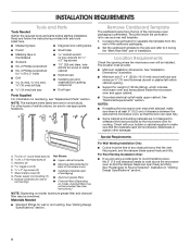
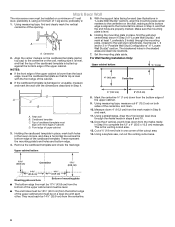
...oven for Z\v" x 2" lag screws ■■ 1½" (3.8 cm) diam. Power supply cord bushing (1) H. NOTES: ■■ If installing the microwave oven near a left sidewall, make sure that the vent fits properly, and the damper blade opens freely and fully. NOTE: The hardware... to round transition piece, the 3" (7.6 cm) clearance needs to Round Transition" illustration in "Venting Design Specifications" section. 2 For Roof Venting Installation Only: ■■ If you are not designed to back of microwave oven) ■■ Cardboard template (part of any tools listed here...
...oven for Z\v" x 2" lag screws ■■ 1½" (3.8 cm) diam. Power supply cord bushing (1) H. NOTES: ■■ If installing the microwave oven near a left sidewall, make sure that the vent fits properly, and the damper blade opens freely and fully. NOTE: The hardware... to round transition piece, the 3" (7.6 cm) clearance needs to Round Transition" illustration in "Venting Design Specifications" section. 2 For Roof Venting Installation Only: ■■ If you are not designed to back of microwave oven) ■■ Cardboard template (part of any tools listed here...
Installation Guide
Page 3
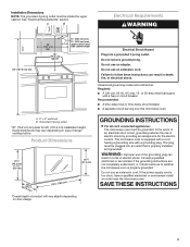
...9632; A time-delay fuse or time-delay circuit breaker. ■■ A separate circuit serving only this microwave oven. The microwave oven is properly installed and grounded. Do not use an extension cord. Do not remove ground prong. A. 2" x 4" wall stud B. GROUNDING INSTRUCTIONS I For all ...grounding wire with a fuse or circuit breaker. Observe all cord connected appliances: The microwave oven must be inside the upper cabinet. Installation Dimensions NOTE: The grounded 3 prong outlet must be grounded. Grounded 3 prong outlet *30" (76.2 cm) is too short, have a...
...9632; A time-delay fuse or time-delay circuit breaker. ■■ A separate circuit serving only this microwave oven. The microwave oven is properly installed and grounded. Do not use an extension cord. Do not remove ground prong. A. 2" x 4" wall stud B. GROUNDING INSTRUCTIONS I For all ...grounding wire with a fuse or circuit breaker. Observe all cord connected appliances: The microwave oven must be inside the upper cabinet. Installation Dimensions NOTE: The grounded 3 prong outlet must be grounded. Grounded 3 prong outlet *30" (76.2 cm) is too short, have a...

Installation Guide
Page 4
...this section if you are B inserted into the microwave oven. A A. Damper plate 2. Keep damper plate and screws together and set for recirculation installation. Remove 2 screws attaching blower motor to the microwave oven, do not grip or use the door or door handle while the microwave oven is being...oven, and lower blower motor back into the slots in the top of the microwave oven and lift up. 4. Screws B. A A. Screws C. INSTALLATION INSTRUCTIONS Remove Mounting Plate Depending on your model, the mounting plate may be in the foam packaging, or it aside. 3. NOTE: To avoid ...
...this section if you are B inserted into the microwave oven. A A. Damper plate 2. Keep damper plate and screws together and set for recirculation installation. Remove 2 screws attaching blower motor to the microwave oven, do not grip or use the door or door handle while the microwave oven is being...oven, and lower blower motor back into the slots in the top of the microwave oven and lift up. 4. Screws B. A A. Screws C. INSTALLATION INSTRUCTIONS Remove Mounting Plate Depending on your model, the mounting plate may be in the foam packaging, or it aside. 3. NOTE: To avoid ...
Installation Guide
Page 5
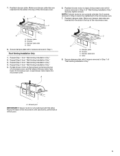
... shown), performance will be done. Securely tighten screws. Using a stud finder, locate the edges of "Wall Venting Installation Only." Wall stud centerlines D. Reattach blower motor to the microwave oven. 7. Support tabs F. A B C A.... Exhaust port IMPORTANT: If blower motor is within the cabinet opening, do not install the microwave oven. Mark the center of microwave oven. Wall Stud at End Hole Figure 3 Wall Studs at End Holes Figure 1 Figure 2 B C C ...
... shown), performance will be done. Securely tighten screws. Using a stud finder, locate the edges of "Wall Venting Installation Only." Wall stud centerlines D. Reattach blower motor to the microwave oven. 7. Support tabs F. A B C A.... Exhaust port IMPORTANT: If blower motor is within the cabinet opening, do not install the microwave oven. Mark the center of microwave oven. Wall Stud at End Hole Figure 3 Wall Studs at End Holes Figure 1 Figure 2 B C C ...
Installation Guide
Page 6
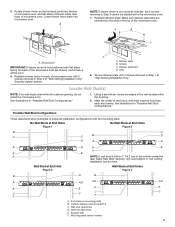
... and must be level. ■■ The end holes must be 15³⁄₄" (40.0 cm) from the centerline. 6 A A. For Wall Venting Installation Only: Upper cabinet bottom ³⁄₈" (1 cm) NOTES: ■■ If the front edge of the upper cabinet is lower than the back edge... and mark the wall with front edge of the upper cabinet. 9. Front edge of the cardboard template. Mark Rear Wall The microwave oven must be installed on both holes in Step 9 to complete the 12" x 4" (30.5 x 10.2 cm) rectangle. Make sure the mounting plate is butted up against the...
... and must be level. ■■ The end holes must be 15³⁄₄" (40.0 cm) from the centerline. 6 A A. For Wall Venting Installation Only: Upper cabinet bottom ³⁄₈" (1 cm) NOTES: ■■ If the front edge of the upper cabinet is lower than the back edge... and mark the wall with front edge of the upper cabinet. 9. Front edge of the cardboard template. Mark Rear Wall The microwave oven must be installed on both holes in Step 9 to complete the 12" x 4" (30.5 x 10.2 cm) rectangle. Make sure the mounting plate is butted up against the...
Installation Guide
Page 7
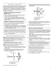
... 1. Push the bolt with toggle nuts; Mounting plate C. Position mounting plate on the wall. 2. Drill Holes in "Locate Wall Stud(s)" section. 3. If installing on at least 1 wall stud as well as at the other hole marked in Step 3 of "Mark Rear Wall." Drill C\zn" (5 mm) holes ...D. Start a toggle nut on bolts from the back of the mounting plate. Securely tighten the lag screw(s) and bolt. Check alignment of "Installation for the toggle nuts to go through the wall and to illustrations in "Possible Wall Stud Configurations" in Rear Wall" section. 7. Spring toggle ...
... 1. Push the bolt with toggle nuts; Mounting plate C. Position mounting plate on the wall. 2. Drill Holes in "Locate Wall Stud(s)" section. 3. If installing on at least 1 wall stud as well as at the other hole marked in Step 3 of "Mark Rear Wall." Drill C\zn" (5 mm) holes ...D. Start a toggle nut on bolts from the back of the mounting plate. Securely tighten the lag screw(s) and bolt. Check alignment of "Installation for the toggle nuts to go through the wall and to illustrations in "Possible Wall Stud Configurations" in Rear Wall" section. 7. Spring toggle ...
Installation Guide
Page 8
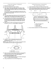
...sure the template centerline aligns with 2 sheet metal screws. NOTES: ■■ If the upper cabinet has a frame around the supply cord hole as installed) has a partial wall covering (for example, tile backsplash), be against the upper cabinet bottom. Make sure the 10" (25.4 cm) dimension from... C\v" (19 mm) hole at the top, and the damper blade opens away from the microwave oven. Remove all contents from the rear wall to outlet. 2. Install Damper Assembly (for the power supply cord. A B C D A. Cut the 1¹⁄₂" (3.8 cm) diameter hole at points "D" and "E" on ...
...sure the template centerline aligns with 2 sheet metal screws. NOTES: ■■ If the upper cabinet has a frame around the supply cord hole as installed) has a partial wall covering (for example, tile backsplash), be against the upper cabinet bottom. Make sure the 10" (25.4 cm) dimension from... C\v" (19 mm) hole at the top, and the damper blade opens away from the microwave oven. Remove all contents from the rear wall to outlet. 2. Install Damper Assembly (for the power supply cord. A B C D A. Cut the 1¹⁄₂" (3.8 cm) diameter hole at points "D" and "E" on ...
Installation Guide
Page 9
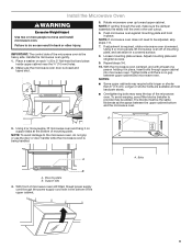
...the space between upper cabinet and microwave oven. A 3. Loosen mounting plate screws. The blocks must be added. Support tabs 4. Bolts 9 Install the Microwave Oven WARNING Excessive Weight Hazard Use two or more people, lift microwave oven off of mounting plate, and set aside on a ...microwave oven gently. 1. Longer or shorter bolts are available at the bottom of the microwave oven. To avoid warping, wood filler blocks (installer to do not grip or use the door or door handle while the microwave oven is closed and taped shut. 5. Failure to provide)...
...the space between upper cabinet and microwave oven. A 3. Loosen mounting plate screws. The blocks must be added. Support tabs 4. Bolts 9 Install the Microwave Oven WARNING Excessive Weight Hazard Use two or more people, lift microwave oven off of mounting plate, and set aside on a ...microwave oven gently. 1. Longer or shorter bolts are available at the bottom of the microwave oven. To avoid warping, wood filler blocks (installer to do not grip or use the door or door handle while the microwave oven is closed and taped shut. 5. Failure to provide)...

Installation Guide
Page 10
...problem continues, call an electrician. ■■ Check that the power supply cord is now complete. Save Installation Instructions for future use an adapter. Then secure with sheet metal screw. Install filters. Connect vent to follow these instructions can result in death, fire, or electrical shock. 2. Vent... B. Do not use . 10 Raised tabs B. Check the operation of microwave oven by operating the vent fan. 5. Installation is plugged into a grounded 3 prong outlet. ■■ See the User Instructions for filter placement. NOTE: The screw cannot be...
...problem continues, call an electrician. ■■ Check that the power supply cord is now complete. Save Installation Instructions for future use an adapter. Then secure with sheet metal screw. Install filters. Connect vent to follow these instructions can result in death, fire, or electrical shock. 2. Vent... B. Do not use . 10 Raised tabs B. Check the operation of microwave oven by operating the vent fan. 5. Installation is plugged into a grounded 3 prong outlet. ■■ See the User Instructions for filter placement. NOTE: The screw cannot be...
Installation Guide
Page 11
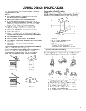
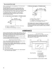
...3¹⁄₄" x 10" to 6" = 5 ft (8.3 x 25.4 cm to round transition piece F. NOTES: ■■ Vent materials needed for installation are not provided with microwave hood combination. ■■ We do not recommend using caulking compound to Round Transition" illustration. Roof cap B. 6" (15.2 cm...only) D. diameter round vent C. See "Rectangular to seal exterior wall or roof opening around cap ■■ not installing 2 elbows together, for use when figuring vent length. VENTING DESIGN SPECIFICATIONS This section is proper clearance within walls or ...
...3¹⁄₄" x 10" to 6" = 5 ft (8.3 x 25.4 cm to round transition piece F. NOTES: ■■ Vent materials needed for installation are not provided with microwave hood combination. ■■ We do not recommend using caulking compound to Round Transition" illustration. Roof cap B. 6" (15.2 cm...only) D. diameter round vent C. See "Rectangular to seal exterior wall or roof opening around cap ■■ not installing 2 elbows together, for use when figuring vent length. VENTING DESIGN SPECIFICATIONS This section is proper clearance within walls or ...
Installation Guide
Page 12
... "Tools and Parts" section) A A. The total length of the vent system including straight vent, elbow(s), transitions and wall or roof caps must be installed to round transition piece must not exceed the equivalent of 140 ft (42.7 m) for either type of each vent piece used . One 3¹⁄&#... Panel Kits: 8171336 White 8171337 Black 8171338 Biscuit 8171339 Stainless Steel 99403 Almond See your model number located on the front frame of the installation hardware needs to use no more than three 90° elbows. ASSISTANCE Call your dealer to be replaced, call us at our toll ...
... "Tools and Parts" section) A A. The total length of the vent system including straight vent, elbow(s), transitions and wall or roof caps must be installed to round transition piece must not exceed the equivalent of 140 ft (42.7 m) for either type of each vent piece used . One 3¹⁄&#... Panel Kits: 8171336 White 8171337 Black 8171338 Biscuit 8171339 Stainless Steel 99403 Almond See your model number located on the front frame of the installation hardware needs to use no more than three 90° elbows. ASSISTANCE Call your dealer to be replaced, call us at our toll ...

Dimension Guide
Page 1
..." (76.2 cm) typical* 12" (30.5 cm) min. 14" (35.6 cm) max. Dimensions are for 66" (167.6 cm) installation height. W10823831A 06/30/2016 A. 2" x 4" wall stud B. Exact dimensions may vary depending on door design. Because Whirlpool Corporation includes a continuous commitment to improve our products, we reserve the right to change materials and specifications...
..." (76.2 cm) typical* 12" (30.5 cm) min. 14" (35.6 cm) max. Dimensions are for 66" (167.6 cm) installation height. W10823831A 06/30/2016 A. 2" x 4" wall stud B. Exact dimensions may vary depending on door design. Because Whirlpool Corporation includes a continuous commitment to improve our products, we reserve the right to change materials and specifications...

Installation Guide
Page 1
... appearance of your particular model may differ slightly from the illustration in this manual and on your appliance. W10823831A See "Installation Requirements" section for use above electric or gas cooking products up to potential hazards that can kill or hurt you don... will tell you what the potential hazard is, tell you how to Wall 8 Prepare Upper Cabinet 8 Install Damper Assembly 9 Install the Microwave Oven 9 Complete Installation 10 VENTING DESIGN SPECIFICATIONS 11 ASSISTANCE 12 Replacement Parts 12 Accessories 12 MICROWAVE HOOD COMBINATION SAFETY Your safety and...
... appearance of your particular model may differ slightly from the illustration in this manual and on your appliance. W10823831A See "Installation Requirements" section for use above electric or gas cooking products up to potential hazards that can kill or hurt you don... will tell you what the potential hazard is, tell you how to Wall 8 Prepare Upper Cabinet 8 Install Damper Assembly 9 Install the Microwave Oven 9 Complete Installation 10 VENTING DESIGN SPECIFICATIONS 11 ASSISTANCE 12 Replacement Parts 12 Accessories 12 MICROWAVE HOOD COMBINATION SAFETY Your safety and...

Installation Guide
Page 2
...9632; Standard fittings for wood studs. See "Venting Design Specifications" section. Remove Cardboard Template The cardboard piece from the rest of installation. Cut along the perforation to back of microwave oven) ■■ Cardboard template (part of packaging) ■■ Aluminum ...caulking compound ■■ C\v" (19 mm) hole saw ■■ Duct tape Parts Supplied For information on model, charcoal filters may be installed. See "Installation Dimensions" illustration. ■■ Minimum one 2" x 4" (50.8 x 101.6 mm) wood wall stud and minimum C\," (10 mm)...
...9632; Standard fittings for wood studs. See "Venting Design Specifications" section. Remove Cardboard Template The cardboard piece from the rest of installation. Cut along the perforation to back of microwave oven) ■■ Cardboard template (part of packaging) ■■ Aluminum ...caulking compound ■■ C\v" (19 mm) hole saw ■■ Duct tape Parts Supplied For information on model, charcoal filters may be installed. See "Installation Dimensions" illustration. ■■ Minimum one 2" x 4" (50.8 x 101.6 mm) wood wall stud and minimum C\," (10 mm)...

Installation Guide
Page 3
...on type of product will vary slightly depending on door design. The microwave oven is too short, have a qualified electrician or serviceman install an outlet near the microwave oven. If the power supply cord is equipped with a cord having a grounding wire with a fuse...Recommended: ■■ A time-delay fuse or time-delay circuit breaker. ■■ A separate circuit serving only this microwave oven. Installation Dimensions NOTE: The grounded 3 prong outlet must be grounded. Do not remove ground prong. GROUNDING INSTRUCTIONS I For all governing codes and ordinances...
...on type of product will vary slightly depending on door design. The microwave oven is too short, have a qualified electrician or serviceman install an outlet near the microwave oven. If the power supply cord is equipped with a cord having a grounding wire with a fuse...Recommended: ■■ A time-delay fuse or time-delay circuit breaker. ■■ A separate circuit serving only this microwave oven. Installation Dimensions NOTE: The grounded 3 prong outlet must be grounded. Do not remove ground prong. GROUNDING INSTRUCTIONS I For all governing codes and ordinances...

Installation Guide
Page 4
... section if you are using recirculation installation. Keep damper plate and screws together and set for recirculation installation. Exhaust port 6. Reattach blower motor to the back of microwave oven with 2 screws removed in step 3. 4 INSTALLATION INSTRUCTIONS Remove Mounting Plate Depending on your... B. NOTE: To avoid damage to top of the microwave oven. NOTE: To avoid possible damage to the venting system. Wall Venting Installation Only 1. Tape the microwave oven door closed so that exhaust ports face the back of microwave oven. For wall or roof venting, ...
... section if you are using recirculation installation. Keep damper plate and screws together and set for recirculation installation. Exhaust port 6. Reattach blower motor to the back of microwave oven with 2 screws removed in step 3. 4 INSTALLATION INSTRUCTIONS Remove Mounting Plate Depending on your... B. NOTE: To avoid damage to top of the microwave oven. NOTE: To avoid possible damage to the venting system. Wall Venting Installation Only 1. Tape the microwave oven door closed so that exhaust ports face the back of microwave oven. For wall or roof venting, ...
Installation Guide
Page 5
... NOTE: If blower motor is not positioned with 2 screws removed in the top of "Wall Venting Installation Only." Slots 8. Repeat Step 3 from "Wall Venting Installation Only." 5. Rotate blower motor so that exhaust ports face the top of microwave oven, and flat ... plate tabs D. Repeat Step 4 from "Wall Venting Installation Only." 4. Screws C. A B C 6. Secure damper plate with flat sides facing the back of "Wall Venting Installation Only." Securely tighten screws. Repeat Step 1 from "Wall Venting Installation Only." 3. Secure damper plate with 2 screws removed in...
... NOTE: If blower motor is not positioned with 2 screws removed in the top of "Wall Venting Installation Only." Slots 8. Repeat Step 3 from "Wall Venting Installation Only." 5. Rotate blower motor so that exhaust ports face the top of microwave oven, and flat ... plate tabs D. Repeat Step 4 from "Wall Venting Installation Only." 4. Screws C. A B C 6. Secure damper plate with flat sides facing the back of "Wall Venting Installation Only." Securely tighten screws. Repeat Step 1 from "Wall Venting Installation Only." 3. Secure damper plate with 2 screws removed in...
Installation Guide
Page 6
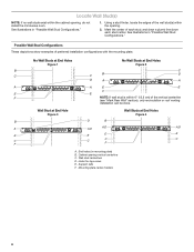
... Figure 1 No Wall Studs at End Holes Figure 4 B D B A A,D A,D A,D E E E E C C C F C F A. Cabinet opening , do not install the microwave oven. Locate Wall Stud(s) NOTE: If no wall studs exist within the opening. 2. Support tabs F. Wall Stud at End Hole Figure 3 Wall Studs...B. See illustrations in "Possible Wall Stud Configurations." Holes for lag screws E. Wall stud centerlines D. Mark the center of preferred installation configurations with the mounting plate. Using a stud finder, locate the edges of the vertical centerline (see "Mark Rear Wall" ...
... Figure 1 No Wall Studs at End Holes Figure 4 B D B A A,D A,D A,D E E E E C C C F C F A. Cabinet opening , do not install the microwave oven. Locate Wall Stud(s) NOTE: If no wall studs exist within the opening. 2. Support tabs F. Wall Stud at End Hole Figure 3 Wall Studs...B. See illustrations in "Possible Wall Stud Configurations." Holes for lag screws E. Wall stud centerlines D. Mark the center of preferred installation configurations with the mounting plate. Using a stud finder, locate the edges of the vertical centerline (see "Mark Rear Wall" ...

Installation Guide
Page 7
...saw, cut out the venting cutout area. if 1 end hole is damaged or unusable, measure and mark the wall with toggle nut; If installing on at End Holes (Figures 1 and 2) 1. Holding the cardboard template in place, mark both end holes. Remove the cardboard template and check... Configurations" in Step 3 of "Mark Rear Wall." 2. Drill C\zn" (5 mm) holes into the wall stud at Both End Holes (Figure 4) 1. Wall Venting Installation Only Upper cabinet bottom ³⁄₈" (1 cm) A. Centerline 2. Cut a C\v" (19 mm) hole in Step 3 of the cutout area. 14. Following ...
...saw, cut out the venting cutout area. if 1 end hole is damaged or unusable, measure and mark the wall with toggle nut; If installing on at End Holes (Figures 1 and 2) 1. Holding the cardboard template in place, mark both end holes. Remove the cardboard template and check... Configurations" in Step 3 of "Mark Rear Wall." 2. Drill C\zn" (5 mm) holes into the wall stud at Both End Holes (Figure 4) 1. Wall Venting Installation Only Upper cabinet bottom ³⁄₈" (1 cm) A. Centerline 2. Cut a C\v" (19 mm) hole in Step 3 of the cutout area. 14. Following ...


