
Dimension Guide
Page 1
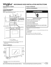
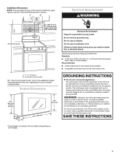
... circuit breaker ■■ A separate circuit serving only this microwave oven A. 2" x 4" wall stud B. Page 1 of range/ cooktop below. W10918334 06/01/2017 Do not remove ground prong. MICROWAVE HOOD INSTALLATION INSTRUCTIONS PRODUCT MODEL NUMBERS WMH31017H LOCATION REQUIREMENTS Installation Dimensions NOTE: The grounded 3 prong outlet must be inside the upper cabinet. Because Whirlpool Corporation includes a continuous commitment to improve our products, we reserve the right to change materials and specifications without notice. A B PRODUCT DIMENSIONS ELECTRICAL...
... circuit breaker ■■ A separate circuit serving only this microwave oven A. 2" x 4" wall stud B. Page 1 of range/ cooktop below. W10918334 06/01/2017 Do not remove ground prong. MICROWAVE HOOD INSTALLATION INSTRUCTIONS PRODUCT MODEL NUMBERS WMH31017H LOCATION REQUIREMENTS Installation Dimensions NOTE: The grounded 3 prong outlet must be inside the upper cabinet. Because Whirlpool Corporation includes a continuous commitment to improve our products, we reserve the right to change materials and specifications without notice. A B PRODUCT DIMENSIONS ELECTRICAL...
Dimension Guide
Page 2
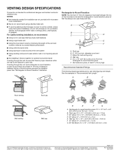
...; Using the most direct route by minimizing the length of the vent and number of the microwave oven and the rectangular to -round transition is used, be sure that the damper can open fully. Dimensions are not provided with product. Specifications subject to change without notice. A B C D E 3" (7.6 cm) F A. For optimal venting installation, we reserve the right to change materials and specifications without notice. A B C Roof venting Roof cap Wall venting Wall cap...
...; Using the most direct route by minimizing the length of the vent and number of the microwave oven and the rectangular to -round transition is used, be sure that the damper can open fully. Dimensions are not provided with product. Specifications subject to change without notice. A B C D E 3" (7.6 cm) F A. For optimal venting installation, we reserve the right to change materials and specifications without notice. A B C Roof venting Roof cap Wall venting Wall cap...

Owners Manual
Page 1
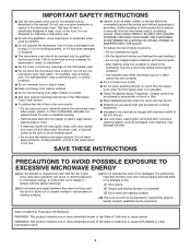
... can be killed or seriously injured if you don't follow instructions. User Guide Microwave Hood Combination THANK YOU for example, closed glass jars are able to excessive microwave energy: I Install or locate the microwave oven only in the provided Installation Instructions. Register your model and serial number located on your appliance. Model Number Serial Number MICROWAVE HOOD COMBINATION SAFETY Your safety and the safety of burns, electric shock, fire, injury to persons, or exposure to explode...
... can be killed or seriously injured if you don't follow instructions. User Guide Microwave Hood Combination THANK YOU for example, closed glass jars are able to excessive microwave energy: I Install or locate the microwave oven only in the provided Installation Instructions. Register your model and serial number located on your appliance. Model Number Serial Number MICROWAVE HOOD COMBINATION SAFETY Your safety and the safety of burns, electric shock, fire, injury to persons, or exposure to explode...
Owners Manual
Page 2
... any openings on hood or filter. Stir the liquid both gas and electric cooking equipment. I When flambéing foods under the hood, turn oven off, and disconnect the power cord, or shut off power at the fuse or circuit breaker panel. I Clean Ventilating Hoods Frequently - I Liquids, such as water, coffee, or tea are placed inside the oven ignite, keep oven door closed, turn the fan on sealing surfaces. (c) Do not operate the oven if...
... any openings on hood or filter. Stir the liquid both gas and electric cooking equipment. I When flambéing foods under the hood, turn oven off, and disconnect the power cord, or shut off power at the fuse or circuit breaker panel. I Clean Ventilating Hoods Frequently - I Liquids, such as water, coffee, or tea are placed inside the oven ignite, keep oven door closed, turn the fan on sealing surfaces. (c) Do not operate the oven if...
Owners Manual
Page 3
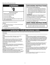
... . Touch and hold number keypad "3" for about 3 seconds until a confirmation tone sounds and "DEMO" icon lights up in the display. Do not use of electric shock by providing an escape wire for about 3 seconds until a tone sounds and the vent fan turns on the magnetron. Recommended: ■■ A time-delay fuse or time-delay circuit breaker. ■■ A separate circuit serving only this microwave oven. Do not use an extension cord. Vent Timer (on . Standby Mode...
... . Touch and hold number keypad "3" for about 3 seconds until a confirmation tone sounds and "DEMO" icon lights up in the display. Do not use of electric shock by providing an escape wire for about 3 seconds until a tone sounds and the vent fan turns on the magnetron. Recommended: ■■ A time-delay fuse or time-delay circuit breaker. ■■ A separate circuit serving only this microwave oven. Do not use an extension cord. Vent Timer (on . Standby Mode...

Owners Manual
Page 4
... Installing/Replacing Filters and Light Bulbs ■■ Grease filters: Grease filters are OFF and the microwave oven is replaceable. Touch DEFROST, enter number code of the turntable (not in ounces: 3.0 or 3.5 (85 or 99 g), then touch Start control. (Baked) Potato Touch (BAKED) POTATO. Touch PIZZA. Preset Cooking Touch COOK, enter number code of the filter into its 2-hook area with screws. ■■ Cavity light: The cavity light bulb is behind the door. To reinstall, place end of food item, enter quantity, then touch...
... Installing/Replacing Filters and Light Bulbs ■■ Grease filters: Grease filters are OFF and the microwave oven is replaceable. Touch DEFROST, enter number code of the turntable (not in ounces: 3.0 or 3.5 (85 or 99 g), then touch Start control. (Baked) Potato Touch (BAKED) POTATO. Touch PIZZA. Preset Cooking Touch COOK, enter number code of the filter into its 2-hook area with screws. ■■ Cavity light: The cavity light bulb is behind the door. To reinstall, place end of food item, enter quantity, then touch...
Owners Manual
Page 5
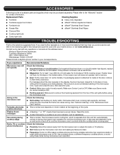
... a household fuse has blown or a circuit breaker has tripped, replace the fuse or reset the circuit breaker. On some models) is a list of the door, remove it, then firmly close door. Reset the clock. ■■ A letter followed by mail with your correspondence. Please refer to inside of available parts and supplies which is separate from the vent fan, automatically comes on cavity walls, microwave inlet cover, cooking rack supports, and area where the door touches...
... a household fuse has blown or a circuit breaker has tripped, replace the fuse or reset the circuit breaker. On some models) is a list of the door, remove it, then firmly close door. Reset the clock. ■■ A letter followed by mail with your correspondence. Please refer to inside of available parts and supplies which is separate from the vent fan, automatically comes on cavity walls, microwave inlet cover, cooking rack supports, and area where the door touches...
Owners Manual
Page 6
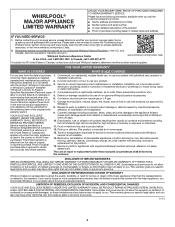
... appliances or built-in -home repair. and Canada, direct all requests for 8. ONE YEAR LIMITED WARRANTY WHAT IS COVERED WHAT IS NOT COVERED For one year from natural gas or L.P. operated and maintained according to chemicals. labor to access additional resources, or visit www.whirlpool.com/product_help. 2. In the event of the Use and Care Guide, scan the QR code on the...
... appliances or built-in -home repair. and Canada, direct all requests for 8. ONE YEAR LIMITED WARRANTY WHAT IS COVERED WHAT IS NOT COVERED For one year from natural gas or L.P. operated and maintained according to chemicals. labor to access additional resources, or visit www.whirlpool.com/product_help. 2. In the event of the Use and Care Guide, scan the QR code on the...
Installation Instructions
Page 1
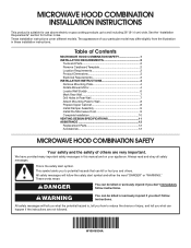
..."WARNING." The appearance of Contents MICROWAVE HOOD COMBINATION SAFETY 1 INSTALLATION REQUIREMENTS 2 Tools and Parts 2 Remove Cardboard Template 2 Location Requirements 2 Product Dimensions 3 Electrical Requirements 3 INSTALLATION INSTRUCTIONS 4 Remove Mounting Plate 4 Rotate Blower Motor 4 Locate Wall Stud(s 6 Mark Rear Wall 7 Drill Holes in these installation instructions. Table of your appliance. Always read and obey all safety messages. All safety messages will follow instructions. These installation instructions cover different models. This is , tell you how...
..."WARNING." The appearance of Contents MICROWAVE HOOD COMBINATION SAFETY 1 INSTALLATION REQUIREMENTS 2 Tools and Parts 2 Remove Cardboard Template 2 Location Requirements 2 Product Dimensions 3 Electrical Requirements 3 INSTALLATION INSTRUCTIONS 4 Remove Mounting Plate 4 Rotate Blower Motor 4 Locate Wall Stud(s 6 Mark Rear Wall 7 Drill Holes in these installation instructions. Table of your appliance. Always read and obey all safety messages. All safety messages will follow instructions. These installation instructions cover different models. This is , tell you how...
Installation Instructions
Page 2
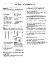
... parts before starting installation. Read and follow the instructions provided with your builder or cabinet supplier to exist above the microwave oven so that the door can open freely and fully. A B C D E FG H A. Z\v-20 x 3" flat-head bolts (2) C. C\zn" toggle nuts (2) E. Sheet metal screws (2) G. See User Instructions.) NOTE: Depending on model, charcoal filters may be included. Materials Needed ■■ Standard fittings for cooking. Cut along the perforation to use as a rear wall template. 1. The location...
... parts before starting installation. Read and follow the instructions provided with your builder or cabinet supplier to exist above the microwave oven so that the door can open freely and fully. A B C D E FG H A. Z\v-20 x 3" flat-head bolts (2) C. C\zn" toggle nuts (2) E. Sheet metal screws (2) G. See User Instructions.) NOTE: Depending on model, charcoal filters may be included. Materials Needed ■■ Standard fittings for cooking. Cut along the perforation to use as a rear wall template. 1. The location...
Installation Instructions
Page 3
..., or electrical shock. SAVE THESE INSTRUCTIONS 3 GROUNDING INSTRUCTIONS I For all governing codes and ordinances. If the power supply cord is equipped with a cord having a grounding wire with a fuse or circuit breaker Recommended: ■■ A time-delay fuse or time-delay circuit breaker ■■ A separate circuit serving only this microwave oven A. 2" x 4" wall stud B. Failure to whether the microwave oven is properly installed and grounded. Observe all cord connected appliances: The microwave oven must be...
..., or electrical shock. SAVE THESE INSTRUCTIONS 3 GROUNDING INSTRUCTIONS I For all governing codes and ordinances. If the power supply cord is equipped with a cord having a grounding wire with a fuse or circuit breaker Recommended: ■■ A time-delay fuse or time-delay circuit breaker ■■ A separate circuit serving only this microwave oven A. 2" x 4" wall stud B. Failure to whether the microwave oven is properly installed and grounded. Observe all cord connected appliances: The microwave oven must be...
Installation Instructions
Page 4
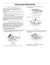
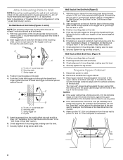
... back of the microwave oven. For wall or roof venting, changes must be made to the back of the microwave oven, remove it may be attached to the venting system. Exhaust port 6. Wall Venting Installation Only 1. A B A. Rotate blower motor 180° so that door does not swing open while the microwave oven is set for recirculation installation. Remove any remaining contents from the microwave oven cavity. 2. A A. Damper plate 2. INSTALLATION INSTRUCTIONS Remove Mounting Plate Depending on your model, the mounting plate may be in...
... back of the microwave oven. For wall or roof venting, changes must be made to the back of the microwave oven, remove it may be attached to the venting system. Exhaust port 6. Wall Venting Installation Only 1. A B A. Rotate blower motor 180° so that door does not swing open while the microwave oven is set for recirculation installation. Remove any remaining contents from the microwave oven cavity. 2. A A. Damper plate 2. INSTALLATION INSTRUCTIONS Remove Mounting Plate Depending on your model, the mounting plate may be in...
Installation Instructions
Page 6
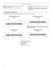
... 2 B C C C B D D A A A A E E F E E F NOTE: If wall stud is within the opening. 2. Holes for lag screws E. Support tabs F. Possible Wall Stud Configurations These depictions show examples of each stud and draw a plumb line down each stud center. End holes (on mounting plate) B. Cabinet opening , do not install the microwave oven. See illustrations in "Possible Wall Stud Configurations." Locate Wall Stud(s) NOTE: If no wall studs exist within the cabinet opening vertical centerline...
... 2 B C C C B D D A A A A E E F E E F NOTE: If wall stud is within the opening. 2. Holes for lag screws E. Support tabs F. Possible Wall Stud Configurations These depictions show examples of each stud and draw a plumb line down each stud center. End holes (on mounting plate) B. Cabinet opening , do not install the microwave oven. See illustrations in "Possible Wall Stud Configurations." Locate Wall Stud(s) NOTE: If no wall studs exist within the cabinet opening vertical centerline...
Installation Instructions
Page 7
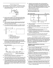
... 8 and 10. 12. Wall Venting Installation Only Upper cabinet bottom ³⁄₈" (1 cm) A. Rear wall B. Using a straightedge, draw the 2 horizontal, level lines through the wall at both end holes. Using a keyhole saw, cut out the venting cutout area. Drill B\," (16 mm) holes through the mounting plate, closest to figures 1 and 2 in "Possible Wall Stud Configurations" in the "Locate Wall Stud(s)" section. Holding the mounting plate in place, find and...
... 8 and 10. 12. Wall Venting Installation Only Upper cabinet bottom ³⁄₈" (1 cm) A. Rear wall B. Using a straightedge, draw the 2 horizontal, level lines through the wall at both end holes. Using a keyhole saw, cut out the venting cutout area. Drill B\," (16 mm) holes through the mounting plate, closest to figures 1 and 2 in "Possible Wall Stud Configurations" in the "Locate Wall Stud(s)" section. Holding the mounting plate in place, find and...
Installation Instructions
Page 8
... the 10" (25.4 cm) dimension from upper cabinet. 3. Position mounting plate on the wall. 4. Disconnect power to points "D" and "E" on at least 1 wall stud as well as at End Holes" in the "Drill Holes in the "Locate Wall Stud(s)" section. The template has trim lines to use as guides. ■■ If the wall behind the microwave oven (as installed) has a partial wall covering (for example, tile backsplash), be...
... the 10" (25.4 cm) dimension from upper cabinet. 3. Position mounting plate on the wall. 4. Disconnect power to points "D" and "E" on at least 1 wall stud as well as at End Holes" in the "Drill Holes in the "Locate Wall Stud(s)" section. The template has trim lines to use as guides. ■■ If the wall behind the microwave oven (as installed) has a partial wall covering (for example, tile backsplash), be...

Installation Instructions
Page 9
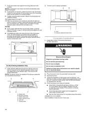
.... A B C D A. Cut C\v" (19 mm) hole at points "D" and "E" on Upper Cabinet Template. 8. Position the damper assembly on each Z\v-20 x 3" flat-head bolt and place inside upper cabinet near the C\," (10 mm) holes. 3. With front of the vent grille before using the microwave oven. Metal cabinet B. 5. These are for the power supply cord. Install Damper Assembly (for wall venting only) 1. Support tabs 5. Make sure the microwave oven door is being handled. Damper blade D. IMPORTANT: The control side of microwave oven B. A. Sheet metal screws 3.
.... A B C D A. Cut C\v" (19 mm) hole at points "D" and "E" on Upper Cabinet Template. 8. Position the damper assembly on each Z\v-20 x 3" flat-head bolt and place inside upper cabinet near the C\," (10 mm) holes. 3. With front of the vent grille before using the microwave oven. Metal cabinet B. 5. These are for the power supply cord. Install Damper Assembly (for wall venting only) 1. Support tabs 5. Make sure the microwave oven door is being handled. Damper blade D. IMPORTANT: The control side of microwave oven B. A. Sheet metal screws 3.
Installation Instructions
Page 10
... mounting plate and hold in death, fire, or electrical shock. 2. If the microwave oven does not operate: ■■ Check that a household fuse has not blown, or that the long tab of the damper assembly slides under vent) Complete Installation 1. Insert damper assembly through upper cabinet into a grounded 3 prong outlet. ■■ See the User Instructions for future use. 10 Upper cabinet cutout E. Do not use an extension cord. Reconnect power. 4. Replace the fuse or reset...
... mounting plate and hold in death, fire, or electrical shock. 2. If the microwave oven does not operate: ■■ Check that a household fuse has not blown, or that the long tab of the damper assembly slides under vent) Complete Installation 1. Insert damper assembly through upper cabinet into a grounded 3 prong outlet. ■■ See the User Instructions for future use. 10 Upper cabinet cutout E. Do not use an extension cord. Reconnect power. 4. Replace the fuse or reset...

Installation Instructions
Page 11
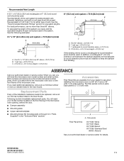
...; Vent materials needed for installation are for the damper to vent air outside, unless using recirculation installation. If venting through the wall, be sure to open freely and fully. See "Rectangular-to 15.2 cm = 1.5 m) B. A B C D E 3" (7.6 cm) F A. See the examples in the vent system ■■ Using caulking compound to seal exterior wall or roof opening around cap ■■ Not installing 2 elbows together for optimal hood performance If venting...
...; Vent materials needed for installation are for the damper to vent air outside, unless using recirculation installation. If venting through the wall, be sure to open freely and fully. See "Rectangular-to 15.2 cm = 1.5 m) B. A B C D E 3" (7.6 cm) F A. See the examples in the vent system ■■ Using caulking compound to seal exterior wall or roof opening around cap ■■ Not installing 2 elbows together for optimal hood performance If venting...
Installation Instructions
Page 12
... for details. ASSISTANCE Call your model number located on the front facing of the installation hardware needs to -round transition piece = 5 ft (1.5 m) D. 2 ft (0.6 m) + 6 ft (1.8 m) straight = 8 ft (2.4 m) If the existing vent is located behind the door. ■■ Damper assembly ■■ Mounting plate ■■ Upper cabinet template ■■ Mounting Screw Kit (includes parts A through G in "Parts Supplied" in the system. Accessories Filler Panel Kits are available from sticking. W10918334A...
... for details. ASSISTANCE Call your model number located on the front facing of the installation hardware needs to -round transition piece = 5 ft (1.5 m) D. 2 ft (0.6 m) + 6 ft (1.8 m) straight = 8 ft (2.4 m) If the existing vent is located behind the door. ■■ Damper assembly ■■ Mounting plate ■■ Upper cabinet template ■■ Mounting Screw Kit (includes parts A through G in "Parts Supplied" in the system. Accessories Filler Panel Kits are available from sticking. W10918334A...

Specification Sheet
Page 1
...-Safe Turntable Plate Clean up spills on the turntable by simply putting it in the U.S.A. General Features & Properties 2-Speed, 300 CFM Motor Class Add 30 Seconds Option Adjustable Cooktop Lighting Electrical Details Amps 16 Volts 120 Also available in: White WMH31017HW Black WMH31017HB Stainless Steel WMH31017HS Technical Details Microwave Type CFMs Lighting Type Number of Speeds Venting Type Dimensions Product Dimensions (H x W x D) Depth with Door Open 90° Cutout Dimensions (W x D) Reference Material Dimension Guide Install Guide Use & Care Guide Warranty...
...-Safe Turntable Plate Clean up spills on the turntable by simply putting it in the U.S.A. General Features & Properties 2-Speed, 300 CFM Motor Class Add 30 Seconds Option Adjustable Cooktop Lighting Electrical Details Amps 16 Volts 120 Also available in: White WMH31017HW Black WMH31017HB Stainless Steel WMH31017HS Technical Details Microwave Type CFMs Lighting Type Number of Speeds Venting Type Dimensions Product Dimensions (H x W x D) Depth with Door Open 90° Cutout Dimensions (W x D) Reference Material Dimension Guide Install Guide Use & Care Guide Warranty...


