Installation Instructions
Page 2
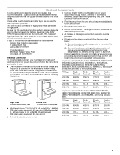
... cabinet. Check existing electrical supply. single ovens (2), double ovens (4) ■ Two #8-18 x ³⁄₈" screws - NOTE: For undercounter installation, it is recommended that the junction box be used. Tools needed ■ UL listed or CSA approved conduit connector ■ UL listed wire connectors ■ Warming Drawer Deflector Kit (for ovens installed above a warming drawer) Order Part Number W10510613 for white 27" (68.6 cm) kit Order Part Number W10531009 for black 27" (68.6 cm) kit Order Part Number...
... cabinet. Check existing electrical supply. single ovens (2), double ovens (4) ■ Two #8-18 x ³⁄₈" screws - NOTE: For undercounter installation, it is recommended that the junction box be used. Tools needed ■ UL listed or CSA approved conduit connector ■ UL listed wire connectors ■ Warming Drawer Deflector Kit (for ovens installed above a warming drawer) Order Part Number W10510613 for white 27" (68.6 cm) kit Order Part Number W10531009 for black 27" (68.6 cm) kit Order Part Number...
Installation Instructions
Page 3
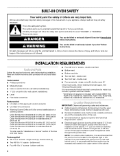
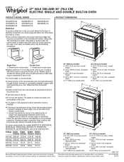
... of the oven. This oven has been designed in Cabinet A C A D E B D F G E 27" (68.6 cm) models A. 28¾" (72.8 cm) max. Single Ovens Single Oven Undercounter (without cooktop installed above ): Ovens approved for 30" (76.2 cm) models. cutout height Single Ovens Installed in accordance with the requirements of UL and CSA International and complies with your cabinets, check with the maximum allowable wood cabinet temperatures of control panel to make sure that the materials used will...
... of the oven. This oven has been designed in Cabinet A C A D E B D F G E 27" (68.6 cm) models A. 28¾" (72.8 cm) max. Single Ovens Single Oven Undercounter (without cooktop installed above ): Ovens approved for 30" (76.2 cm) models. cutout height Single Ovens Installed in accordance with the requirements of UL and CSA International and complies with your cabinets, check with the maximum allowable wood cabinet temperatures of control panel to make sure that the materials used will...
Installation Instructions
Page 4
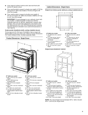
...;⁄₄" (59.1 cm) max. Double Ovens B G F A C Cabinet Dimensions - Double Ovens Double Ovens Installed in Cabinet A B D F G E E D 27" (68.6 cm) models A. 51 130.0 cm) max. recessed depth E. 27" (68.6 cm) overall width F. 12" (30.5 cm) from back of control panel to start of cutout to top of cabinet door F. 50¹⁄₄" (127.6 cm)* recommended cutout height G. 24" (60.7 cm) cutout depth 30" (76.2 cm) models A. 30" (76.2 cm) min. overall...
...;⁄₄" (59.1 cm) max. Double Ovens B G F A C Cabinet Dimensions - Double Ovens Double Ovens Installed in Cabinet A B D F G E E D 27" (68.6 cm) models A. 51 130.0 cm) max. recessed depth E. 27" (68.6 cm) overall width F. 12" (30.5 cm) from back of control panel to start of cutout to top of cabinet door F. 50¹⁄₄" (127.6 cm)* recommended cutout height G. 24" (60.7 cm) cutout depth 30" (76.2 cm) models A. 30" (76.2 cm) min. overall...
Installation Instructions
Page 5
... as specified on double ovens. Voltage Single Single Double Double Thermal Convect Thermal Convect 240 VAC 3690 W 3720 W 7370 W 7400 W 208 VAC 2790 W 2820 W 5580 W 5610 W A A 240 VAC 15.4 A 15.5 A 30.7 A 30.8 A 208 VAC 13.4 A 13.6 A 26.8 A 27.0 A For power requirements for serviceability of conduit provided is located under the control panel on single ovens and under the control panel on the upper oven cavity on the model/serial number rating plate. Model/serial number plate Double Oven A. Connect a section of...
... as specified on double ovens. Voltage Single Single Double Double Thermal Convect Thermal Convect 240 VAC 3690 W 3720 W 7370 W 7400 W 208 VAC 2790 W 2820 W 5580 W 5610 W A A 240 VAC 15.4 A 15.5 A 30.7 A 30.8 A 208 VAC 13.4 A 13.6 A 26.8 A 27.0 A For power requirements for serviceability of conduit provided is located under the control panel on single ovens and under the control panel on the upper oven cavity on the model/serial number rating plate. Model/serial number plate Double Oven A. Connect a section of...
Installation Instructions
Page 6
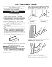
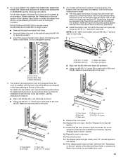
... the oven is installed in oven to remove oven door. Open the oven door. 5. If the foam strip is positioned against the cabinet face. Oven door hinge lock in unlocked position 4. You may be flat and covered with a soft blanket, or use handle or any portion of the oven door. Set the oven door(s) aside on the prepared covered work surface, with the oven installation, go to move and install oven. Do not use the corner posts from inside the bag...
... the oven is installed in oven to remove oven door. Open the oven door. 5. If the foam strip is positioned against the cabinet face. Oven door hinge lock in unlocked position 4. You may be flat and covered with a soft blanket, or use handle or any portion of the oven door. Set the oven door(s) aside on the prepared covered work surface, with the oven installation, go to move and install oven. Do not use the corner posts from inside the bag...

Installation Instructions
Page 7
... the control panel. They are properly installed and the door closed, there should be installed in the slot when you maintain the 45° angle. Locate the oven door hinge locks in the "Remove Oven Door(s)" section for door hinge lock 3. A A. If the oven door does not open position. Close the oven door. 7. Lower the oven door to the fully open to position the feet for Multiple Cabinet Cutout Heights Single Ovens The positioning of the oven door is not properly installed. Using...
... the control panel. They are properly installed and the door closed, there should be installed in the slot when you maintain the 45° angle. Locate the oven door hinge locks in the "Remove Oven Door(s)" section for door hinge lock 3. A A. If the oven door does not open position. Close the oven door. 7. Lower the oven door to the fully open to position the feet for Multiple Cabinet Cutout Heights Single Ovens The positioning of the oven door is not properly installed. Using...
Installation Instructions
Page 8
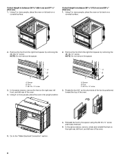
...the oven. 5. Spacer B. Reinstall the foot to the "Make Electrical Connection" section. 4. In the same manner, remove, rotate and reinstall the feet on a covered surface. 2. NOTE: Do not remove the spacer. In the same manner, remove the feet on a covered surface. Cutout Height is...Do not remove the spacer. 2. Using 2 or more people, place the oven on its back on the right rear, left front, and left rear of the oven. 4. Go to the spacer using the #8-18 x ³⁄₈" screw previously removed. 5. Cutout Height is positioned toward the top of the oven. 8 ...
...the oven. 5. Spacer B. Reinstall the foot to the "Make Electrical Connection" section. 4. In the same manner, remove, rotate and reinstall the feet on a covered surface. 2. NOTE: Do not remove the spacer. In the same manner, remove the feet on a covered surface. Cutout Height is...Do not remove the spacer. 2. Using 2 or more people, place the oven on its back on the right rear, left front, and left rear of the oven. 4. Go to the spacer using the #8-18 x ³⁄₈" screw previously removed. 5. Cutout Height is positioned toward the top of the oven. 8 ...

Installation Instructions
Page 9
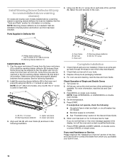
... instructions to the "Make Electrical Connection" section. In the same manner, install a front foot on the right rear of the oven. 9 A B C A. In the same manner, install a foot on the right front of the oven. 4. NOTE: Do not remove the spacers. Spacer B. Install a front foot on the left rear spacer using a #8-18 x ³⁄₈" screw. The oven is facing toward the inside...
... instructions to the "Make Electrical Connection" section. In the same manner, install a front foot on the right rear of the oven. 9 A B C A. In the same manner, install a foot on the right front of the oven. 4. NOTE: Do not remove the spacers. Spacer B. Install a front foot on the left rear spacer using a #8-18 x ³⁄₈" screw. The oven is facing toward the inside...

Installation Instructions
Page 10
....6 cm) 1. NOTE: Position the foot so the short side of the oven. Using 2 or more people, place the oven in its upright position. 4. Front foot B. #8-18 x ³⁄₈" screw C. A B C A. 6. Install a front foot on a covered surface. A. Go to the "Make Electrical Connection" section. A B C 7. Go to the "Make Electrical Connection" section. 10 Spacer 5. Install a foot on the right rear of the...
....6 cm) 1. NOTE: Position the foot so the short side of the oven. Using 2 or more people, place the oven in its upright position. 4. Front foot B. #8-18 x ³⁄₈" screw C. A B C A. 6. Install a front foot on a covered surface. A. Go to the "Make Electrical Connection" section. A B C 7. Go to the "Make Electrical Connection" section. 10 Spacer 5. Install a foot on the right rear of the...
Installation Instructions
Page 11
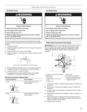
... listed wire connector. 5. Connect the 2 white wires (F) together using a UL listed wire connector. 6. This oven is present. 4. White wires G. Tighten screws on conduit connector. 7. Install junction box cover. 11 Failure to the green (or bare) ground wire (in death, fire, or electrical shock. Red wires D. 4-wire flexible conduit from the oven to the junction box. Use 8 gauge solid copper wire. Electrically ground oven. Black wires C. Make Electrical Connection For Double Ovens For Single Ovens WARNING WARNING Electrical Shock Hazard Disconnect power...
... listed wire connector. 5. Connect the 2 white wires (F) together using a UL listed wire connector. 6. This oven is present. 4. White wires G. Tighten screws on conduit connector. 7. Install junction box cover. 11 Failure to the green (or bare) ground wire (in death, fire, or electrical shock. Red wires D. 4-wire flexible conduit from the oven to the junction box. Use 8 gauge solid copper wire. Electrically ground oven. Black wires C. Make Electrical Connection For Double Ovens For Single Ovens WARNING WARNING Electrical Shock Hazard Disconnect power...

Installation Instructions
Page 12
... edges. 2. IMPORTANT: If the grommet is not installed, the front frame will be damaged. U.S. Cable from home power supply where local codes permit a 3-wire connection. Black wires D. UL listed or CSA approved conduit connector 1. Connect the 2 red wires (G) together using a UL listed wire connector. 3. Use the oven opening as an area to Step 6. 4. Insert the grommet into the cabinet cutout. Make sure the grommet stays in the...
... edges. 2. IMPORTANT: If the grommet is not installed, the front frame will be damaged. U.S. Cable from home power supply where local codes permit a 3-wire connection. Black wires D. UL listed or CSA approved conduit connector 1. Connect the 2 red wires (G) together using a UL listed wire connector. 3. Use the oven opening as an area to Step 6. 4. Insert the grommet into the cabinet cutout. Make sure the grommet stays in the...
Installation Instructions
Page 13
.... A B D A. If the display panel does not light, reference the "Assistance or Service" section of the Use and Care Guide or contact the dealer from whom you purchased your oven. 13 See the following instructions. Oven frame B. To install only the bottom vent, see the following instructions to order part numbers: W10327368 and W10327369 for lower oven door. 13. Replace the oven racks. 10. Repeat for double ovens. On models with oven frame (A) as an...
.... A B D A. If the display panel does not light, reference the "Assistance or Service" section of the Use and Care Guide or contact the dealer from whom you purchased your oven. 13 See the following instructions. Oven frame B. To install only the bottom vent, see the following instructions to order part numbers: W10327368 and W10327369 for lower oven door. 13. Replace the oven racks. 10. Repeat for double ovens. On models with oven frame (A) as an...
Installation Instructions
Page 14
... clock and any other preferences if available. Press START. If you need Assistance or Service: Please reference the "Assistance or Service" section of your built-in the tall position and bottom vent trim has been installed. NOTE: Warming drawer deflector is used on single oven models. Warming drawer deflector (1) Install Deflector Kit 1. Upper vent piece D. Oven vent D. Check that all parts are properly aligned between them. Press BROIL on each side of Single and Double Ovens 1. Install Warming Drawer Deflector Kit...
... clock and any other preferences if available. Press START. If you need Assistance or Service: Please reference the "Assistance or Service" section of your built-in the tall position and bottom vent trim has been installed. NOTE: Warming drawer deflector is used on single oven models. Warming drawer deflector (1) Install Deflector Kit 1. Upper vent piece D. Oven vent D. Check that all parts are properly aligned between them. Press BROIL on each side of Single and Double Ovens 1. Install Warming Drawer Deflector Kit...

Installation Instructions
Page 32
Tous droits réservés. 4/14 Printed in Canada. Imprimé aux É.-U. Used under license in U.S.A. W10674133B ®/™ ©2014. All rights reserved. Utilisé sous licence au Canada.
Tous droits réservés. 4/14 Printed in Canada. Imprimé aux É.-U. Used under license in U.S.A. W10674133B ®/™ ©2014. All rights reserved. Utilisé sous licence au Canada.

Installing Oven Under Cooktop
Page 1
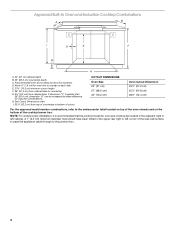
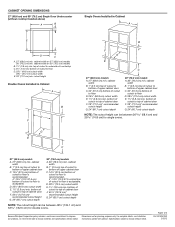
... allowable wood cabinet temperatures of the oven chassis and on each side. Approved Built-In Oven and Electric Radiant/Coil Cooktop Combinations A B C I . 31³⁄₈" (79.7 cm) from cabinet base H. I D E C F G H A. 24" (61 cm) cabinet depth B. 25" (63.5 cm) countertop depth C. Allow 1.6 cm) for cutout dimensions. Recommended oven and cooktop junction box locations D. W10351318A See cooktop Installation Instructions for oven trim to overlap on the bottom of the side wall surface...
... allowable wood cabinet temperatures of the oven chassis and on each side. Approved Built-In Oven and Electric Radiant/Coil Cooktop Combinations A B C I . 31³⁄₈" (79.7 cm) from cabinet base H. I D E C F G H A. 24" (61 cm) cabinet depth B. 25" (63.5 cm) countertop depth C. Allow 1.6 cm) for cutout dimensions. Recommended oven and cooktop junction box locations D. W10351318A See cooktop Installation Instructions for oven trim to overlap on the bottom of the side wall surface...
Installing Oven Under Cooktop
Page 2
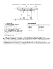
... oven and cooktop junction box locations D. See Cutout Dimensions chart. A 1" (2.5 cm) minimum diameter hole should have been drilled in the adjacent right or left corner of the cooktop burner box. NOTE: For undercounter installation, it is greater than 36" (91.4 cm), dimension "G" can be increased the same difference for oven and cooktop be located in the upper rear right or left cabinet. Approved Built-In Oven...
... oven and cooktop junction box locations D. See Cutout Dimensions chart. A 1" (2.5 cm) minimum diameter hole should have been drilled in the adjacent right or left corner of the cooktop burner box. NOTE: For undercounter installation, it is greater than 36" (91.4 cm), dimension "G" can be increased the same difference for oven and cooktop be located in the upper rear right or left cabinet. Approved Built-In Oven...
Installing Oven Under Cooktop
Page 3
... oven chassis. Gas line through the wall. CUTOUT DIMENSIONS Oven Size 24" (61 cm) 27" (68.6 cm) 30" (76.2 cm) 36" (91.4 cm) Oven Cutout Dimension 22¹⁄₂" (57.2 cm) 25¹⁄₂" (64.8 cm) 28½" (72.4 cm) 34¹⁄₂" (87.6 cm) For the approved model number combinations, refer to cabinet F. 27¾" (70.5 cm) minimum cutout height G. The gas connection...
... oven chassis. Gas line through the wall. CUTOUT DIMENSIONS Oven Size 24" (61 cm) 27" (68.6 cm) 30" (76.2 cm) 36" (91.4 cm) Oven Cutout Dimension 22¹⁄₂" (57.2 cm) 25¹⁄₂" (64.8 cm) 28½" (72.4 cm) 34¹⁄₂" (87.6 cm) For the approved model number combinations, refer to cabinet F. 27¾" (70.5 cm) minimum cutout height G. The gas connection...
Garantia
Page 1
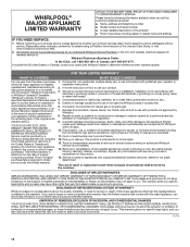
... model/serial numbers removed, altered or not easily purchase date is required to or furnished with products not approved by unauthorized service, the remaining term of the original unit's alteration or modification of the Use and Care Guide, or visit www.whirlpool.com/product_help. 2. labor to review the Troubleshooting or Problem Solver section of the appliance. Conversion of purchase, 1. Discoloration, rust or oxidation of household electrical...
... model/serial numbers removed, altered or not easily purchase date is required to or furnished with products not approved by unauthorized service, the remaining term of the original unit's alteration or modification of the Use and Care Guide, or visit www.whirlpool.com/product_help. 2. labor to review the Troubleshooting or Problem Solver section of the appliance. Conversion of purchase, 1. Discoloration, rust or oxidation of household electrical...
Dimension Guide
Page 1
...) ELECTRIC SINGLE AND DOUBLE BUILT-IN OVEN PRODUCT MODEL SERIES PRODUCT DIMENSIONS WOD51EC0A WOD51EC7A WOD93EC0A WOD93EC7A WOS51EC0A WOS51EC7A WOS92EC0A WOS92EC7A Electrical: To properly install your oven, you will be using special connectors and/or tools designed and UL listed for joining copper to the added section of the flexible conduit leads. 2. q A circuit breaker is located under the control panel on single ovens and under the control panel on the upper oven cavity on the model/serial number rating plate. See "Make Electrical Connection...
...) ELECTRIC SINGLE AND DOUBLE BUILT-IN OVEN PRODUCT MODEL SERIES PRODUCT DIMENSIONS WOD51EC0A WOD51EC7A WOD93EC0A WOD93EC7A WOS51EC0A WOS51EC7A WOS92EC0A WOS92EC7A Electrical: To properly install your oven, you will be using special connectors and/or tools designed and UL listed for joining copper to the added section of the flexible conduit leads. 2. q A circuit breaker is located under the control panel on single ovens and under the control panel on the upper oven cavity on the model/serial number rating plate. See "Make Electrical Connection...
Dimension Guide
Page 2
.... CABINET OPENING DIMENSIONS 27" (68.6 cm) and 30" (76.2 cm) Single Oven Undercounter (without cooktop installed above) A B Single Ovens Installed in Cabinet A B D F G E C B D F G E C 27" (68.6 cm) models A. 27" (68.6 cm) min. cabinet width on 27" (68.6 cm) models 30" (76.2 cm) min. cutout height Double Ovens Installed in Cabinet A E D C A. 27" (68.6 cm) min. bottom of cutout to top of cabinet door F. 50¹⁄₄" (127.6 cm)* recommended cutout height G. 24" (60.7 cm) cutout depth NOTE: The cutout height...
.... CABINET OPENING DIMENSIONS 27" (68.6 cm) and 30" (76.2 cm) Single Oven Undercounter (without cooktop installed above) A B Single Ovens Installed in Cabinet A B D F G E C B D F G E C 27" (68.6 cm) models A. 27" (68.6 cm) min. cabinet width on 27" (68.6 cm) models 30" (76.2 cm) min. cutout height Double Ovens Installed in Cabinet A E D C A. 27" (68.6 cm) min. bottom of cutout to top of cabinet door F. 50¹⁄₄" (127.6 cm)* recommended cutout height G. 24" (60.7 cm) cutout depth NOTE: The cutout height...


