
Dimension Guide
Page 1
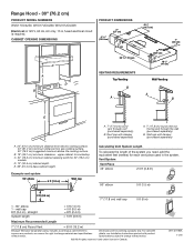
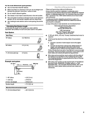
... to change without notice. B. Range Hood - 30" (76.2 cm) PRODUCT MODEL NUMBERS WVU17UC0JS0, WVU17UC0JB0, WVU17UC0JW0 Electrical: A 120 V, 60 Hz, AC only, 15 A, fused electrical circuit is required. Wall cap with damper (purchased separately) Calculating Vent System Length To calculate the length of the system you need, add the equivalent feet (meters) for each vent piece used in Canada. W11407190A 11/19 B. 18" (45.7 cm) minimum clearance - Vent System Vent Piece 45° elbow 2.5 ft...
... to change without notice. B. Range Hood - 30" (76.2 cm) PRODUCT MODEL NUMBERS WVU17UC0JS0, WVU17UC0JB0, WVU17UC0JW0 Electrical: A 120 V, 60 Hz, AC only, 15 A, fused electrical circuit is required. Wall cap with damper (purchased separately) Calculating Vent System Length To calculate the length of the system you need, add the equivalent feet (meters) for each vent piece used in Canada. W11407190A 11/19 B. 18" (45.7 cm) minimum clearance - Vent System Vent Piece 45° elbow 2.5 ft...
Owners Manual
Page 1
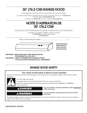
... 2 Models/Modèles: WVU17UC0JS , WVU17UC0JB, WVU17UC0JW IMPORTANT: READ AND SAVE THESE INSTRUCTIONS. 30" (76.2 CM) RANGE HOOD Installation Instructions and Use & Care Guide For questions about features, operation/performance, parts, accessories or service, call: 1-800-253-1301 or visit our website at www.whirlpool.com In Canada, call 1-800-807-6777 or visit our website at www.whirlpool.ca HOTTE D'ASPIRATION DE 30" (76,2 CM) Instructions d'installation et Guide d'utilisation...
... 2 Models/Modèles: WVU17UC0JS , WVU17UC0JB, WVU17UC0JW IMPORTANT: READ AND SAVE THESE INSTRUCTIONS. 30" (76.2 CM) RANGE HOOD Installation Instructions and Use & Care Guide For questions about features, operation/performance, parts, accessories or service, call: 1-800-253-1301 or visit our website at www.whirlpool.com In Canada, call 1-800-807-6777 or visit our website at www.whirlpool.ca HOTTE D'ASPIRATION DE 30" (76,2 CM) Instructions d'installation et Guide d'utilisation...
Owners Manual
Page 2
... for proper combustion and exhausting of gases through the flue (chimney) of the surface element. Use proper pan size. BE CAREFUL TO PREVENT BURNS. you may ignite. Use an extinguisher ONLY if: - The fire is needed for examination and/or repair. READ AND SAVE THESE INSTRUCTIONS TABLE OF CONTENTS RANGE HOOD SAFETY 1 INSTALLATION REQUIREMENTS 3 INSTALLATION INSTRUCTIONS 6 RANGE HOOD USE 10 RANGE HOOD CARE 10 WIRING DIAGRAM 11 ASSISTANCE OR SERVICE 12 WARRANTY 13 TABLE DES MATI...
... for proper combustion and exhausting of gases through the flue (chimney) of the surface element. Use proper pan size. BE CAREFUL TO PREVENT BURNS. you may ignite. Use an extinguisher ONLY if: - The fire is needed for examination and/or repair. READ AND SAVE THESE INSTRUCTIONS TABLE OF CONTENTS RANGE HOOD SAFETY 1 INSTALLATION REQUIREMENTS 3 INSTALLATION INSTRUCTIONS 6 RANGE HOOD USE 10 RANGE HOOD CARE 10 WIRING DIAGRAM 11 ASSISTANCE OR SERVICE 12 WARRANTY 13 TABLE DES MATI...
Owners Manual
Page 3
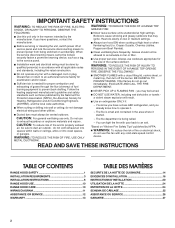
... codes and ordinances. For Mobile Home Installations The installation of 40,000 Btus or less. Read and follow the instructions provided with wall or roof cap Duct tape Optional accessories Recirculating kit (Charcoal filter)" Part Number W11371717 Power cord kit Part Number W10355452* Stainless steel cleaner and polish Part Number 31462A* *For information on the model/serial rating plate. Consult the cooktop/range manufacturer installation instructions before starting installation. It is recommended for vented installations. This range hood is the installer's responsibility...
... codes and ordinances. For Mobile Home Installations The installation of 40,000 Btus or less. Read and follow the instructions provided with wall or roof cap Duct tape Optional accessories Recirculating kit (Charcoal filter)" Part Number W11371717 Power cord kit Part Number W10355452* Stainless steel cleaner and polish Part Number 31462A* *For information on the model/serial rating plate. Consult the cooktop/range manufacturer installation instructions before starting installation. It is recommended for vented installations. This range hood is the installer's responsibility...

Owners Manual
Page 4
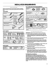
... (recirculating) installations. Roof cap with damper (purchased separately) Cold Weather Installations An additional back draft damper should be installed to minimize backward cold air flow and a thermal break should be installed to minimize conduction of outside temperatures as possible to the outdoors, except for 36" (91.4 cm) models. Do not use a 4" (10.2 cm) laundry-type wall cap. upper cabinet to provide efficient performance. 4 E. 36" (91.4 cm) base cabinet height...
... (recirculating) installations. Roof cap with damper (purchased separately) Cold Weather Installations An additional back draft damper should be installed to minimize backward cold air flow and a thermal break should be installed to minimize conduction of outside temperatures as possible to the outdoors, except for 36" (91.4 cm) models. Do not use a 4" (10.2 cm) laundry-type wall cap. upper cabinet to provide efficient performance. 4 E. 36" (91.4 cm) base cabinet height...
Owners Manual
Page 5
... the electrical connector manufacturer's recommended procedure. Wire sizes and connections must conform to the requirements of straight vent between the elbows if more than 1 elbow is required. Use clamps or duct tape to seal exterior wall or roof opening around the cap. The model/serial plate is located behind the filter on the model/serial rating plate. If codes permit and a separate ground wire is used, it is recommended that a qualified electrician determine that the electrical installation is a minimum...
... the electrical connector manufacturer's recommended procedure. Wire sizes and connections must conform to the requirements of straight vent between the elbows if more than 1 elbow is required. Use clamps or duct tape to seal exterior wall or roof opening around the cap. The model/serial plate is located behind the filter on the model/serial rating plate. If codes permit and a separate ground wire is used, it is recommended that a qualified electrician determine that the electrical installation is a minimum...
Owners Manual
Page 6
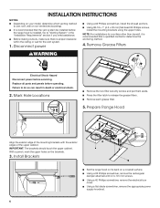
... mounting brackets with 3.5 x 9.5 mm screws. NOTE: For installations to do so can result in the "Installation Requirements" section if you need assistance. Failure to a surface other than drywall, it is recommended that the vent system be installed before the range hood is installed. Using a #2 Phillips screwdriver, remove the electrical box cover. INSTALLATION INSTRUCTIONS NOTES: Depending on your model, determine which venting method to release the grease filters. Press the filter latch to use: roof, wall or non-vented (recirculating...
... mounting brackets with 3.5 x 9.5 mm screws. NOTE: For installations to do so can result in the "Installation Requirements" section if you need assistance. Failure to a surface other than drywall, it is recommended that the vent system be installed before the range hood is installed. Using a #2 Phillips screwdriver, remove the electrical box cover. INSTALLATION INSTRUCTIONS NOTES: Depending on your model, determine which venting method to release the grease filters. Press the filter latch to use: roof, wall or non-vented (recirculating...
Owners Manual
Page 7
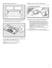
... of the cabinet: - Using a jigsaw or keyhole saw, cut the vent opening outline on the cabinet bottom. OPTIONAL: Mark the hole in the back of the mounting plate against the wall. - Remove the range hood and set it aside. 7 A Using the 7" (17.8 cm) round vent mounting plate, draw the vent opening 1" (2.5 cm) larger than the 7" (17.8 cm) hole traced (dashed line). Mark the hole at the power supply knockout...
... of the cabinet: - Using a jigsaw or keyhole saw, cut the vent opening outline on the cabinet bottom. OPTIONAL: Mark the hole in the back of the mounting plate against the wall. - Remove the range hood and set it aside. 7 A Using the 7" (17.8 cm) round vent mounting plate, draw the vent opening 1" (2.5 cm) larger than the 7" (17.8 cm) hole traced (dashed line). Mark the hole at the power supply knockout...
Owners Manual
Page 8
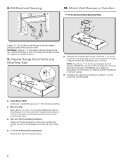
... range hood as accessories. Mounting Tabs Start a #8-18 x " (4.2 x 16 mm) truss-head screw into the mounting tab holes. Non-vent (Recirculating) Installations Using a #2 Phillips screwdriver remove the 2 screws and remove the top, front rectangular vent cover (E). Attach Vent Damper or Transition 7" (17.8 cm) Round Vent Mounting Plate A C B Using a 1 " (3 cm) drill bit, drill the hole in the dot marked previously at an approximate 45° angle in an upward direction. 9. NOTE: An optional 7" (17.8 cm) round damper (A), Part Number...
... range hood as accessories. Mounting Tabs Start a #8-18 x " (4.2 x 16 mm) truss-head screw into the mounting tab holes. Non-vent (Recirculating) Installations Using a #2 Phillips screwdriver remove the 2 screws and remove the top, front rectangular vent cover (E). Attach Vent Damper or Transition 7" (17.8 cm) Round Vent Mounting Plate A C B Using a 1 " (3 cm) drill bit, drill the hole in the dot marked previously at an approximate 45° angle in an upward direction. 9. NOTE: An optional 7" (17.8 cm) round damper (A), Part Number...
Owners Manual
Page 9
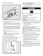
... non-vented (recirculating) installations: Install a charcoal filter. Complete the Installation Install a 120V, 75W maximum, incandescent light bulb with the power cord kit. Check the operation of the range hood and attach to do so can result in terminal box. 11. Make Electrical Connection A B Fire Hazard Electrically ground the blower. Reconnect power. See the "Assistance or Service" section for use from the power supply to green ground screw in death, fire, or electrical shock. Direct Wire Installations Use a UL Listed/CSA Approved wire connector...
... non-vented (recirculating) installations: Install a charcoal filter. Complete the Installation Install a 120V, 75W maximum, incandescent light bulb with the power cord kit. Check the operation of the range hood and attach to do so can result in terminal box. 11. Make Electrical Connection A B Fire Hazard Electrically ground the blower. Reconnect power. See the "Assistance or Service" section for use from the power supply to green ground screw in death, fire, or electrical shock. Direct Wire Installations Use a UL Listed/CSA Approved wire connector...
Owners Manual
Page 10
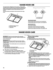
...-vented (recirculating) installations: The charcoal filter is complete to the right for Low speed. Push the grease filter retainer to turn the fan Off. Grease filters C. Push the filter into the channel at the rear of the hood. For best results, start the hood before operating hood. Grease filter retainer C. Return the fan switch to the center to the following instructions. RANGE HOOD CARE Cleaning IMPORTANT: Clean the hood and grease filters frequently according to turn the light Off. Remove the screw from the cooktop area. For stainless steel models, use...
...-vented (recirculating) installations: The charcoal filter is complete to the right for Low speed. Push the grease filter retainer to turn the fan Off. Grease filters C. Push the filter into the channel at the rear of the hood. For best results, start the hood before operating hood. Grease filter retainer C. Return the fan switch to the center to the following instructions. RANGE HOOD CARE Cleaning IMPORTANT: Clean the hood and grease filters frequently according to turn the light Off. Remove the screw from the cooktop area. For stainless steel models, use...
Owners Manual
Page 11
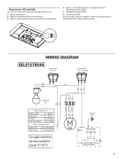
... Frequency Current Power absorption 120VAC 60Hz 1.2±10%A 73±10% W Motor resistance (ohms) White - Remove the fused light bulb from the hood. 3. Off - Red White - Screw a 120V, 9W maximum, LED light bulb with E26 base into the socket. 5. Disconnect power. 2. If the new light does not operate, make sure the light bulb is inserted correctly before calling service. WIRING DIAGRAM SEL0157858A Light Switch Off - Remove the grease filters from behind the lamp spacer. 4. Reconnect power. Replace the grease filters. 6.
... Frequency Current Power absorption 120VAC 60Hz 1.2±10%A 73±10% W Motor resistance (ohms) White - Remove the fused light bulb from the hood. 3. Off - Red White - Screw a 120V, 9W maximum, LED light bulb with E26 base into the socket. 5. Disconnect power. 2. If the new light does not operate, make sure the light bulb is inserted correctly before calling service. WIRING DIAGRAM SEL0157858A Light Switch Off - Remove the grease filters from behind the lamp spacer. 4. Reconnect power. Replace the grease filters. 6.
Owners Manual
Page 12
...; replacement parts. Use and maintenance procedures. Accessory and repair parts sales. Mississauga, Ontario L5N 0B7 Please include a daytime phone number in your nearest Whirlpool designated service center. If you need replacement parts If you can write to your request. Referrals to Whirlpool with any questions or concerns at www.whirlpool.com. To locate FSP® replacement parts in the United States. In Canada Call the Whirlpool Canada LP Customer eXperience Centre toll free...
...; replacement parts. Use and maintenance procedures. Accessory and repair parts sales. Mississauga, Ontario L5N 0B7 Please include a daytime phone number in your nearest Whirlpool designated service center. If you need replacement parts If you can write to your request. Referrals to Whirlpool with any questions or concerns at www.whirlpool.com. To locate FSP® replacement parts in the United States. In Canada Call the Whirlpool Canada LP Customer eXperience Centre toll free...


