
Dimension Guide
Page 1
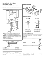
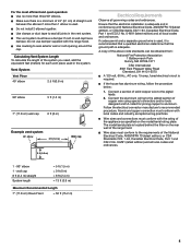
... 1/2" (47 cm) Wall Venting A B E A. 24" (61.0 cm) minimum distance from electric cooking surface. 24" (61.0 cm) minimum distance from gas cooking surface. 30" (76.2 cm) suggested maximum above the cooking surface. D. 12" (30.5 cm) cabinet depth. upper cabinet to change without notice. Range Hood - 30" (76.2 cm) PRODUCT MODEL NUMBERS WVU17UC0JS0, WVU17UC0JB0, WVU17UC0JW0 Electrical: A 120 V, 60 Hz, AC only, 15 A, fused electrical circuit is required. straight System length = 5 ft (1.5 m) = 0 ft...
... 1/2" (47 cm) Wall Venting A B E A. 24" (61.0 cm) minimum distance from electric cooking surface. 24" (61.0 cm) minimum distance from gas cooking surface. 30" (76.2 cm) suggested maximum above the cooking surface. D. 12" (30.5 cm) cabinet depth. upper cabinet to change without notice. Range Hood - 30" (76.2 cm) PRODUCT MODEL NUMBERS WVU17UC0JS0, WVU17UC0JB0, WVU17UC0JW0 Electrical: A 120 V, 60 Hz, AC only, 15 A, fused electrical circuit is required. straight System length = 5 ft (1.5 m) = 0 ft...
Owners Manual
Page 1
... will follow instructions. 30" (76.2 CM) RANGE HOOD Installation Instructions and Use & Care Guide For questions about features, operation/performance, parts, accessories or service, call: 1-800-253-1301 or visit our website at www.whirlpool.com In Canada, call 1-800-807-6777 or visit our website at www.whirlpool.ca HOTTE D'ASPIRATION DE 30" (76,2 CM) Instructions d'installation et Guide d'utilisation et d'entretien Au Canada, pour assistance, installation ou service, composer le...
... will follow instructions. 30" (76.2 CM) RANGE HOOD Installation Instructions and Use & Care Guide For questions about features, operation/performance, parts, accessories or service, call: 1-800-253-1301 or visit our website at www.whirlpool.com In Canada, call 1-800-807-6777 or visit our website at www.whirlpool.ca HOTTE D'ASPIRATION DE 30" (76,2 CM) Instructions d'installation et Guide d'utilisation et d'entretien Au Canada, pour assistance, installation ou service, composer le...
Owners Manual
Page 2
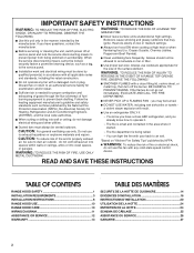
... know how to prevent back drafting. Do not use only. do not damage electrical wiring and other utilities. Always turn off at high settings. Ducted fans must be burned. do not vent exhaust air into spaces within walls or ceilings, attics or into wall or ceiling; METAL DUCTWORK. READ AND SAVE THESE INSTRUCTIONS TABLE OF CONTENTS RANGE HOOD SAFETY 1 INSTALLATION REQUIREMENTS 3 INSTALLATION INSTRUCTIONS 6 RANGE HOOD USE 10 RANGE HOOD CARE 10 WIRING DIAGRAM 11 ASSISTANCE OR SERVICE 12 WARRANTY 13 TABLE DES MATI...
... know how to prevent back drafting. Do not use only. do not damage electrical wiring and other utilities. Always turn off at high settings. Ducted fans must be burned. do not vent exhaust air into spaces within walls or ceilings, attics or into wall or ceiling; METAL DUCTWORK. READ AND SAVE THESE INSTRUCTIONS TABLE OF CONTENTS RANGE HOOD SAFETY 1 INSTALLATION REQUIREMENTS 3 INSTALLATION INSTRUCTIONS 6 RANGE HOOD USE 10 RANGE HOOD CARE 10 WIRING DIAGRAM 11 ASSISTANCE OR SERVICE 12 WARRANTY 13 TABLE DES MATI...
Owners Manual
Page 3
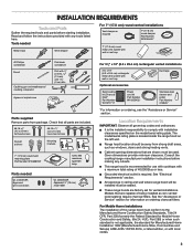
...ordering, see the "Assistance or Service" section. The model/serial rating plate is required. Consult the cooktop/range manufacturer installation instructions before starting installation. Range hood location should be away from package. Check that all governing codes and ordinances. See the "Assistance or Service" section for use with cooktops with wall or roof cap Duct tape Optional accessories Recirculating kit (Charcoal filter)" Part Number W11371717 Power cord kit Part Number W10355452* Stainless steel cleaner and polish Part Number 31462A* *For information on ordering...
...ordering, see the "Assistance or Service" section. The model/serial rating plate is required. Consult the cooktop/range manufacturer installation instructions before starting installation. Range hood location should be away from package. Check that all governing codes and ordinances. See the "Assistance or Service" section for use with cooktops with wall or roof cap Duct tape Optional accessories Recirculating kit (Charcoal filter)" Part Number W11371717 Power cord kit Part Number W10355452* Stainless steel cleaner and polish Part Number 31462A* *For information on ordering...

Owners Manual
Page 4
... as close as part of the thermal break. Top Venting Wall Venting B A A B C A D B E A. 24" (61.0 cm) minimum distance from electric cooking surface. 24" (61.0 cm) minimum distance from gas cooking surface. 30" (76.2 cm) suggested maximum above the cooking surface. Use 7" (17.8 cm) round metal vent. Roof cap with damper (purchased separately) Cold Weather Installations An additional back draft damper should be installed to minimize backward cold air flow and a thermal...
... as close as part of the thermal break. Top Venting Wall Venting B A A B C A D B E A. 24" (61.0 cm) minimum distance from electric cooking surface. 24" (61.0 cm) minimum distance from gas cooking surface. 30" (76.2 cm) suggested maximum above the cooking surface. Use 7" (17.8 cm) round metal vent. Roof cap with damper (purchased separately) Cold Weather Installations An additional back draft damper should be installed to minimize backward cold air flow and a thermal...
Owners Manual
Page 5
... on the rear wall of copper wire using special connectors and/or tools designed and UL listed for each vent piece used . Wire sizes must have a damper. Do not install 2 elbows together. wall cap 8 ft (2.4 m) straight System length = 5 ft (1.5 m) = 0 ft (0 m) = 8 ft (2.4 m) = 13 ft (3.9 m) Maximum Recommended Length 7" (17.8 cm) Round Vent = 50 ft (15.2 m) 5 The model/serial plate is located behind the filter on the model/serial rating plate. Connect the aluminum wiring to seal exterior wall or roof opening around the cap. Make sure there...
... on the rear wall of copper wire using special connectors and/or tools designed and UL listed for each vent piece used . Wire sizes must have a damper. Do not install 2 elbows together. wall cap 8 ft (2.4 m) straight System length = 5 ft (1.5 m) = 0 ft (0 m) = 8 ft (2.4 m) = 13 ft (3.9 m) Maximum Recommended Length 7" (17.8 cm) Round Vent = 50 ft (15.2 m) 5 The model/serial plate is located behind the filter on the model/serial rating plate. Connect the aluminum wiring to seal exterior wall or roof opening around the cap. Make sure there...
Owners Manual
Page 6
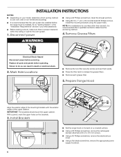
... parts and panels before servicing. Install Brackets Set the range hood on its back on the brackets. 3. IMPORTANT: The brackets should touch the upper cabinet. INSTALLATION INSTRUCTIONS NOTES: Depending on your model, determine which venting method to release the grease filters. Mark Hole Locations Remove the two filter security screws and put them aside. Using a flat-blade screwdriver, remove the appropriate power supply knockout. 6 Press the filter latch to use: roof, wall or non-vented (recirculating). Using a #2 Phillips screwdriver, remove the electrical box cover...
... parts and panels before servicing. Install Brackets Set the range hood on its back on the brackets. 3. IMPORTANT: The brackets should touch the upper cabinet. INSTALLATION INSTRUCTIONS NOTES: Depending on your model, determine which venting method to release the grease filters. Mark Hole Locations Remove the two filter security screws and put them aside. Using a flat-blade screwdriver, remove the appropriate power supply knockout. 6 Press the filter latch to use: roof, wall or non-vented (recirculating). Using a #2 Phillips screwdriver, remove the electrical box cover...
Owners Manual
Page 7
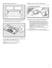
...) hole traced (dashed line). Place the vent mounting plate on the bottom of the range hood. Mark Hole Locations 7. Remove the range hood and set it aside. 7 Position the side edges of the mounting plate between the hole and edge of the cabinet: - Mark the hole at the power supply knockout (B). Using a jigsaw or keyhole saw, cut the vent opening (solid line) on the underside of...
...) hole traced (dashed line). Place the vent mounting plate on the bottom of the range hood. Mark Hole Locations 7. Remove the range hood and set it aside. 7 Position the side edges of the mounting plate between the hole and edge of the cabinet: - Mark the hole at the power supply knockout (B). Using a jigsaw or keyhole saw, cut the vent opening (solid line) on the underside of...
Owners Manual
Page 8
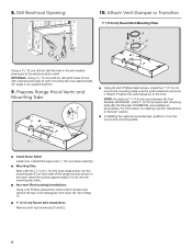
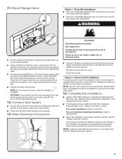
NOTE: An optional 7" (17.8 cm) round damper (A), Part Number W10355451, and a 7" (17.8 cm) round vent mounting plate (B), Part Number W10388168, are available as shown in the inset. Insert the screws approximately 2 turns into the mounting tab (F) on ordering, see the "Assistance or Service" section. Non-vent (Recirculating) Installations Using a #2 Phillips screwdriver remove the 2 screws and remove the top, front rectangular vent cover (E). Mounting Tabs Start a #8-18 x " (4.2 x 16 mm) truss-head screw into the mounting tab holes. Go to...
NOTE: An optional 7" (17.8 cm) round damper (A), Part Number W10355451, and a 7" (17.8 cm) round vent mounting plate (B), Part Number W10388168, are available as shown in the inset. Insert the screws approximately 2 turns into the mounting tab (F) on ordering, see the "Assistance or Service" section. Non-vent (Recirculating) Installations Using a #2 Phillips screwdriver remove the 2 screws and remove the top, front rectangular vent cover (E). Mounting Tabs Start a #8-18 x " (4.2 x 16 mm) truss-head screw into the mounting tab holes. Go to...
Owners Manual
Page 9
... range hood electrical terminal box. Reconnect power. NOTE: Use only with range hood cord connection kits that have been investigated and found acceptable for information on the screws that the back draft dampers work properly. 13. If removed previously, replace the filter. Reinstall the electrical box cover. See the "Assistance or Service" section for use from the fused disconnect (or circuit breaker) box to the cabinet side walls. 11. Use a UL Listed/CSA Approved wire connector and connect the 2 black wires (B) together. Attach the screws...
... range hood electrical terminal box. Reconnect power. NOTE: Use only with range hood cord connection kits that have been investigated and found acceptable for information on the screws that the back draft dampers work properly. 13. If removed previously, replace the filter. Reinstall the electrical box cover. See the "Assistance or Service" section for use from the fused disconnect (or circuit breaker) box to the cabinet side walls. 11. Use a UL Listed/CSA Approved wire connector and connect the 2 black wires (B) together. Attach the screws...
Owners Manual
Page 10
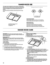
... operating hood. Fan speed switch Operating the light Press the light switch to the left for High speed. RANGE HOOD CARE Cleaning IMPORTANT: Clean the hood and grease filters frequently according to turn the light On. Remove the screw from the kitchen. Glass cleaner to the right for Low speed. Filter retainer screws B. For non-vented (recirculating) installations: The charcoal filter is used in recirculation mode, use cleaners that contain chlorine. On/Off light switch B. Press the fan switch to remove fingerprints. Exterior Surfaces: IMPORTANT: Do not use Stainless Steel...
... operating hood. Fan speed switch Operating the light Press the light switch to the left for High speed. RANGE HOOD CARE Cleaning IMPORTANT: Clean the hood and grease filters frequently according to turn the light On. Remove the screw from the kitchen. Glass cleaner to the right for Low speed. Filter retainer screws B. For non-vented (recirculating) installations: The charcoal filter is used in recirculation mode, use cleaners that contain chlorine. On/Off light switch B. Press the fan switch to remove fingerprints. Exterior Surfaces: IMPORTANT: Do not use Stainless Steel...
Owners Manual
Page 11
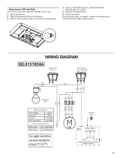
... service. Off - Remove the fused light bulb from the hood. 3. Remove the grease filters from behind the lamp spacer. 4. On Motor Switch Low - Black 17.1±10% Ohms N 13.6±10% Ohms For supply connection use wires suitable for at least 75° (167°F) Ground Screw C25 L G Remote Switch BK BK L For ADA compliance add these elements during the installation 11 Reconnect power. WIRING DIAGRAM SEL0157858A Light Switch Off - Replacing the LED Light Bulb Turn off the range hood...
... service. Off - Remove the fused light bulb from the hood. 3. Remove the grease filters from behind the lamp spacer. 4. On Motor Switch Low - Black 17.1±10% Ohms N 13.6±10% Ohms For supply connection use wires suitable for at least 75° (167°F) Ground Screw C25 L G Remote Switch BK BK L For ADA compliance add these elements during the installation 11 Reconnect power. WIRING DIAGRAM SEL0157858A Light Switch Off - Replacing the LED Light Bulb Turn off the range hood...
Owners Manual
Page 12
... need replacement parts If you need service When calling, please know the purchase date and the complete model and serial number of your appliance. Whirlpool appliances designated service technicians are trained to fulfill the product warranty and provide after -warranty service, anywhere in the United States. Installation information. For further assistance If you need further assistance, you can write to Whirlpool with any questions or concerns at www.whirlpool...
... need replacement parts If you need service When calling, please know the purchase date and the complete model and serial number of your appliance. Whirlpool appliances designated service technicians are trained to fulfill the product warranty and provide after -warranty service, anywhere in the United States. Installation information. For further assistance If you need further assistance, you can write to Whirlpool with any questions or concerns at www.whirlpool...


