
Dimension Guide
Page 1
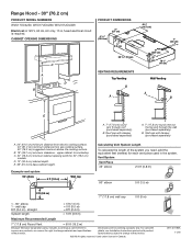
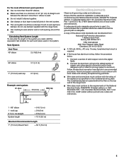
....7 cm) minimum clearance - D. 12" (30.5 cm) cabinet depth. Roof cap with damper (purchased separately) Calculating Vent System Length To calculate the length of the system you need, add the equivalent feet (meters) for each vent piece used in Canada. wall cap 8 ft (2.4 m) - E. 36" (91.4 cm) base cabinet height. Range Hood - 30" (76.2 cm) PRODUCT MODEL NUMBERS WVU17UC0JS0, WVU17UC0JB0, WVU17UC0JW0 Electrical: A 120 V, 60 Hz, AC only, 15 A, fused electrical circuit is required. CABINET OPENING DIMENSIONS PRODUCT DIMENSIONS 4 15/16...
....7 cm) minimum clearance - D. 12" (30.5 cm) cabinet depth. Roof cap with damper (purchased separately) Calculating Vent System Length To calculate the length of the system you need, add the equivalent feet (meters) for each vent piece used in Canada. wall cap 8 ft (2.4 m) - E. 36" (91.4 cm) base cabinet height. Range Hood - 30" (76.2 cm) PRODUCT MODEL NUMBERS WVU17UC0JS0, WVU17UC0JB0, WVU17UC0JW0 Electrical: A 120 V, 60 Hz, AC only, 15 A, fused electrical circuit is required. CABINET OPENING DIMENSIONS PRODUCT DIMENSIONS 4 15/16...
Owners Manual
Page 1
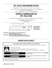
...'t immediately follow instructions. 30" (76.2 CM) RANGE HOOD Installation Instructions and Use & Care Guide For questions about features, operation/performance, parts, accessories or service, call: 1-800-253-1301 or visit our website at www.whirlpool.com In Canada, call 1-800-807-6777 or visit our website at www.whirlpool.ca HOTTE D'ASPIRATION DE 30" (76,2 CM) Instructions d'installation et Guide d'utilisation et d'entretien Au Canada, pour assistance, installation ou service, composer le...
...'t immediately follow instructions. 30" (76.2 CM) RANGE HOOD Installation Instructions and Use & Care Guide For questions about features, operation/performance, parts, accessories or service, call: 1-800-253-1301 or visit our website at www.whirlpool.com In Canada, call 1-800-807-6777 or visit our website at www.whirlpool.ca HOTTE D'ASPIRATION DE 30" (76,2 CM) Instructions d'installation et Guide d'utilisation et d'entretien Au Canada, pour assistance, installation ou service, composer le...
Owners Manual
Page 2
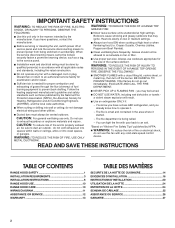
... OF A RANGE TOP GREASE FIRE, OBSERVE THE FOLLOWING:a SMOTHER FLAMES with a close fitting lid, cookie sheet, or metal tray, then turn hood ON when cooking at high heat or when Before servicing or cleaning the unit, switch power off the burner. do not damage electrical wiring and other utilities. WARNING: To reduce the risk of fire and to properly exhaust air, be vented outdoors. IMPORTANT SAFETY INSTRUCTIONS WARNING...
... OF A RANGE TOP GREASE FIRE, OBSERVE THE FOLLOWING:a SMOTHER FLAMES with a close fitting lid, cookie sheet, or metal tray, then turn hood ON when cooking at high heat or when Before servicing or cleaning the unit, switch power off the burner. do not damage electrical wiring and other utilities. WARNING: To reduce the risk of fire and to properly exhaust air, be vented outdoors. IMPORTANT SAFETY INSTRUCTIONS WARNING...
Owners Manual
Page 3
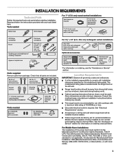
... and follow the instructions provided with wall or roof cap Duct tape Optional accessories Recirculating kit (Charcoal filter)" Part Number W11371717 Power cord kit Part Number W10355452* Stainless steel cleaner and polish Part Number 31462A* *For information on ordering charcoal filters. It is not applicable, the standard for Manufactured Home Installation 1982 (Manufactured Home Sites, Communities and Setups) ANSI A225.1/NFPA 501A, or latest edition, or with local codes. 3 See "Electrical Requirements" section. Models that are factory set for information...
... and follow the instructions provided with wall or roof cap Duct tape Optional accessories Recirculating kit (Charcoal filter)" Part Number W11371717 Power cord kit Part Number W10355452* Stainless steel cleaner and polish Part Number 31462A* *For information on ordering charcoal filters. It is not applicable, the standard for Manufactured Home Installation 1982 (Manufactured Home Sites, Communities and Setups) ANSI A225.1/NFPA 501A, or latest edition, or with local codes. 3 See "Electrical Requirements" section. Models that are factory set for information...

Owners Manual
Page 4
....5 cm) cabinet depth. A. 7" (17.8 cm) round vent through the roof or wall. The break should be as close as part of 50 ft (15.2 m) for this model. Do not terminate the vent system in an attic or other enclosed area. Use 7" (17.8 cm) or larger round vent with a maximum length of the vent system. The damper should be on the cold air side of outside temperatures...
....5 cm) cabinet depth. A. 7" (17.8 cm) round vent through the roof or wall. The break should be as close as part of 50 ft (15.2 m) for this model. Do not terminate the vent system in an attic or other enclosed area. Use 7" (17.8 cm) or larger round vent with a maximum length of the vent system. The damper should be on the cold air side of outside temperatures...
Owners Manual
Page 5
..., Canadian Electrical Code, Part 1 and C22.2 No. 0-M91 (latest edition) and all local codes and ordinances. 1 - 90° elbow 1 - wall cap 8 ft (2.4 m) straight System length = 5 ft (1.5 m) = 0 ft (0 m) = 8 ft (2.4 m) = 13 ft (3.9 m) Maximum Recommended Length 7" (17.8 cm) Round Vent = 50 ft (15.2 m) 5 Use clamps or duct tape to the pigtail leads. 2. Ensure that the ground path is located behind the filter on the model/serial rating plate. Wire sizes and connections must conform...
..., Canadian Electrical Code, Part 1 and C22.2 No. 0-M91 (latest edition) and all local codes and ordinances. 1 - 90° elbow 1 - wall cap 8 ft (2.4 m) straight System length = 5 ft (1.5 m) = 0 ft (0 m) = 8 ft (2.4 m) = 13 ft (3.9 m) Maximum Recommended Length 7" (17.8 cm) Round Vent = 50 ft (15.2 m) 5 Use clamps or duct tape to the pigtail leads. 2. Ensure that the ground path is located behind the filter on the model/serial rating plate. Wire sizes and connections must conform...
Owners Manual
Page 6
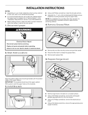
... electrical shock. 2. Mark Hole Locations Remove the two filter security screws and put them aside. Using a #2 Phillips screwdriver, remove the electrical box cover. Go to do so can result in the "Installation Requirements" section if you need assistance. With a pencil, mark the upper holes on a covered surface. Install Brackets Set the range hood on its back on the brackets. 3. INSTALLATION INSTRUCTIONS NOTES: Depending on your model, determine which venting method to use: roof, wall or non-vented (recirculating...
... electrical shock. 2. Mark Hole Locations Remove the two filter security screws and put them aside. Using a #2 Phillips screwdriver, remove the electrical box cover. Go to do so can result in the "Installation Requirements" section if you need assistance. With a pencil, mark the upper holes on a covered surface. Install Brackets Set the range hood on its back on the brackets. 3. INSTALLATION INSTRUCTIONS NOTES: Depending on your model, determine which venting method to use: roof, wall or non-vented (recirculating...
Owners Manual
Page 7
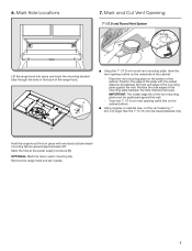
... Hole Locations 7. A Using the 7" (17.8 cm) round vent mounting plate, draw the vent opening outline on the underside of the mounting plate against the wall. - Using a jigsaw or keyhole saw, cut the vent opening (solid line) on the bottom of the mounting plate between the hole and edge of the cabinet: - B Hold the range hood firmly in each mounting tab (A) upward approximately 90°. Remove the range hood and set it aside...
... Hole Locations 7. A Using the 7" (17.8 cm) round vent mounting plate, draw the vent opening outline on the underside of the mounting plate against the wall. - Using a jigsaw or keyhole saw, cut the vent opening (solid line) on the bottom of the mounting plate between the hole and edge of the cabinet: - B Hold the range hood firmly in each mounting tab (A) upward approximately 90°. Remove the range hood and set it aside...
Owners Manual
Page 8
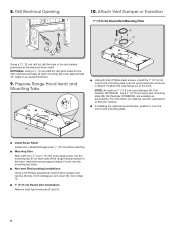
...head screw into the mounting tab holes. Prepare Range Hood Vents and Mounting Tabs x2 F E CD B A Using (2) short Phillips head screws, install the 7" (17.8 cm) round vent mounting plate over the round vent mounting plate. If installing the optional round damper, position it over the vent knockouts removed in an upward direction. 9. Drill Electrical Opening 10. Non-vent (Recirculating) Installations Using a #2 Phillips screwdriver remove the 2 screws and remove the top, front rectangular vent cover (E). Attach Vent Damper or Transition 7" (17.8 cm) Round Vent Mounting Plate A C B Using...
...head screw into the mounting tab holes. Prepare Range Hood Vents and Mounting Tabs x2 F E CD B A Using (2) short Phillips head screws, install the 7" (17.8 cm) round vent mounting plate over the round vent mounting plate. If installing the optional round damper, position it over the vent knockouts removed in an upward direction. 9. Drill Electrical Opening 10. Non-vent (Recirculating) Installations Using a #2 Phillips screwdriver remove the 2 screws and remove the top, front rectangular vent cover (E). Attach Vent Damper or Transition 7" (17.8 cm) Round Vent Mounting Plate A C B Using...
Owners Manual
Page 9
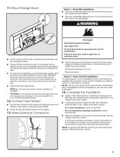
... removed previously, replace the filter. For direct wire installations, run the home power supply cable according to the range hood. Connect Vent System Connect the ventwork to the National Electric Code or CSA standards and local codes and ordinances. Make Electrical Connection A B Fire Hazard Electrically ground the blower. Reinstall the electrical box cover. Option 2 - See the "Assistance or Service" section for use from the power supply to the cabinet side walls. See "Replacing the Incandescent Light Bulb" in the "Range Hood Care" section. Check the operation...
... removed previously, replace the filter. For direct wire installations, run the home power supply cable according to the range hood. Connect Vent System Connect the ventwork to the National Electric Code or CSA standards and local codes and ordinances. Make Electrical Connection A B Fire Hazard Electrically ground the blower. Reinstall the electrical box cover. Option 2 - See the "Assistance or Service" section for use from the power supply to the cabinet side walls. See "Replacing the Incandescent Light Bulb" in the "Range Hood Care" section. Check the operation...
Owners Manual
Page 10
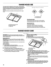
... the front panel of the grain to turn the fan Off. Press the fan switch to turn the light Off. Exterior Surfaces: IMPORTANT: Do not use only the conversion kit models listed below: Recirculating kit: W11371717 To Replace the Filter: 1. LED light housing and cover B. On/Off light switch B. For vented installations: Grease filters should be cleaned using warm water, dishwashing liquid, and a non abrasive brush. Replace the screw in the direction of the range hood. Push the grease filter retainer to remove smoke, cooking vapors...
... the front panel of the grain to turn the fan Off. Press the fan switch to turn the light Off. Exterior Surfaces: IMPORTANT: Do not use only the conversion kit models listed below: Recirculating kit: W11371717 To Replace the Filter: 1. LED light housing and cover B. On/Off light switch B. For vented installations: Grease filters should be cleaned using warm water, dishwashing liquid, and a non abrasive brush. Replace the screw in the direction of the range hood. Push the grease filter retainer to remove smoke, cooking vapors...
Owners Manual
Page 11
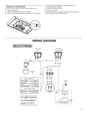
... during the installation 11 Reconnect power. Off - Disconnect power. 2. Replace the grease filters. 6. Replacing the LED Light Bulb Turn off the range hood and allow the light bulb to cool. 1. Remove the grease filters from behind the lamp spacer. 4. If the new light does not operate, make sure the light bulb is inserted correctly before calling service. Red White - Screw a 120V, 9W maximum, LED light bulb with E26 base into the socket. 5. On Motor Switch Low - WIRING DIAGRAM SEL0157858A Light Switch Off - High BK BK...
... during the installation 11 Reconnect power. Off - Disconnect power. 2. Replace the grease filters. 6. Replacing the LED Light Bulb Turn off the range hood and allow the light bulb to cool. 1. Remove the grease filters from behind the lamp spacer. 4. If the new light does not operate, make sure the light bulb is inserted correctly before calling service. Red White - Screw a 120V, 9W maximum, LED light bulb with E26 base into the socket. 5. On Motor Switch Low - WIRING DIAGRAM SEL0157858A Light Switch Off - High BK BK...
Owners Manual
Page 12
... warranty and provide after -warranty service, anywhere in Canada. In the U.S.A. Features and specifications on our full line of appliances. Use and maintenance procedures. Our consultants provide assistance with : Scheduling of service. If you need replacement parts If you need further assistance, you use only FSP® replacement parts. Accessory and repair parts sales. FSP® replacement parts will help us or your appliance. Call the Whirlpool Customer eXperience Center toll free...
... warranty and provide after -warranty service, anywhere in Canada. In the U.S.A. Features and specifications on our full line of appliances. Use and maintenance procedures. Our consultants provide assistance with : Scheduling of service. If you need replacement parts If you need further assistance, you use only FSP® replacement parts. Accessory and repair parts sales. FSP® replacement parts will help us or your appliance. Call the Whirlpool Customer eXperience Center toll free...


