
Owner's Manual
Page 2
Model: Serial No.: The serial number is located on or pinched particularly at plugs, convenience receptacles, and the point where they exit from the apparatus. 11 Only use caution when moving the cart/ apparatus combination to avoid injury from tip-over. 13 Unplug this system in the space below. Install in accordance with the manufacturer's instructions. 8 Do not install near water. 6 Clean only with dry cloth. 7 Do not block any ventilation openings. When a cart is used, use attachments/accessories specified by the manufacturer. 12 Use only with the cart, stand, tripod, bracket, or ...
Model: Serial No.: The serial number is located on or pinched particularly at plugs, convenience receptacles, and the point where they exit from the apparatus. 11 Only use caution when moving the cart/ apparatus combination to avoid injury from tip-over. 13 Unplug this system in the space below. Install in accordance with the manufacturer's instructions. 8 Do not install near water. 6 Clean only with dry cloth. 7 Do not block any ventilation openings. When a cart is used, use attachments/accessories specified by the manufacturer. 12 Use only with the cart, stand, tripod, bracket, or ...

Owner's Manual
Page 3
...high quality shielded cables. Information for the correct method of other Countries outside the European Union] This symbol is too late, YAMAHA and the Electronic Industries Association's Consumer Electronics Group recommend you purchased the items. [Information on different branch (circuit breaker or ... above statements apply ONLY to get the most importantly, without annoying blaring or distortion - We Want You Listening For A Lifetime YAMAHA and the Electronic Industries Association's Consumer Electronics Group want you can be determined by turning the unit "OFF" and "ON", ...
...high quality shielded cables. Information for the correct method of other Countries outside the European Union] This symbol is too late, YAMAHA and the Electronic Industries Association's Consumer Electronics Group recommend you purchased the items. [Information on different branch (circuit breaker or ... above statements apply ONLY to get the most importantly, without annoying blaring or distortion - We Want You Listening For A Lifetime YAMAHA and the Electronic Industries Association's Consumer Electronics Group want you can be determined by turning the unit "OFF" and "ON", ...

Owner's Manual
Page 4
... errors before operating your dealer. • The voltage to be used must be held responsible for selecting this unit, reduce the volume level. YAMAHA shall not be damaged if certain sounds are continuously output, or when the stylus of a turntable touches the surface of a disc, reduce the...of space above , behind and on the floor or other equipment. Thank you for any accident caused by improper placement or installation of speakers. YAMAHA will radiate from the TV set , contact your unit Please read this unit: Glass, china, small metallic, etc. Keep it may cause bodily...
... errors before operating your dealer. • The voltage to be used must be held responsible for selecting this unit, reduce the volume level. YAMAHA shall not be damaged if certain sounds are continuously output, or when the stylus of a turntable touches the surface of a disc, reduce the...of space above , behind and on the floor or other equipment. Thank you for any accident caused by improper placement or installation of speakers. YAMAHA will radiate from the TV set , contact your unit Please read this unit: Glass, china, small metallic, etc. Keep it may cause bodily...

Owner's Manual
Page 5
... the AC outlet 10 AUTOMATIC POWER-SWITCHING FUNCTION ...11 Changing the AUTO STANDBY setting 11 ADJUSTING THE SUBWOOFER BEFORE USE ......12 Frequency characteristics 13 ADVANCED YAMAHA ACTIVE SERVO TECHNOLOGY II 14 IMPORTANT: THE WIRES IN MAINS LEAD ARE COLOURED IN ACCORDANCE WITH THE FOLLOWING CODE: Blue: NEUTRAL Brown: LIVE As the...
... the AC outlet 10 AUTOMATIC POWER-SWITCHING FUNCTION ...11 Changing the AUTO STANDBY setting 11 ADJUSTING THE SUBWOOFER BEFORE USE ......12 Frequency characteristics 13 ADVANCED YAMAHA ACTIVE SERVO TECHNOLOGY II 14 IMPORTANT: THE WIRES IN MAINS LEAD ARE COLOURED IN ACCORDANCE WITH THE FOLLOWING CODE: Blue: NEUTRAL Brown: LIVE As the...

Owner's Manual
Page 6
... • The Automatic power-switching function saves you the trouble of pressing the STANDBY/ON button to turn the power on Advanced Yamaha Active Servo Technology II.) This super-bass sound adds a more realistic, theater-in the four corners of the underside of the subwoofer...can create the best sound quality for details on and off. • This subwoofer system is equipped with a linear port unique to Yamaha that the following parts are contained. SUPPLIED ACCESSORIES After unpacking, check that provides smooth bass response during playback, minimizing extraneous noise not included ...
... • The Automatic power-switching function saves you the trouble of pressing the STANDBY/ON button to turn the power on Advanced Yamaha Active Servo Technology II.) This super-bass sound adds a more realistic, theater-in the four corners of the underside of the subwoofer...can create the best sound quality for details on and off. • This subwoofer system is equipped with a linear port unique to Yamaha that the following parts are contained. SUPPLIED ACCESSORIES After unpacking, check that provides smooth bass response during playback, minimizing extraneous noise not included ...
Owner's Manual
Page 7
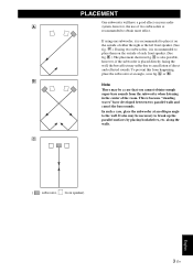
C is also possible, however, if the subwoofer is placed directly facing the wall, the bass effect may be a case that you cannot obtain enough super-bass sounds from happening, place the subwoofer at an oblique angle to the wall. To prevent this from the subwoofer when listening in the center of the room. A or B . along the walls. This is because "standing waves" have a good effect on the outside of two subwoofers is recommended to obtain more effect. A .) If using one subwoofer, it is recommended to place it is recommended to place them on your audio A system, ...
C is also possible, however, if the subwoofer is placed directly facing the wall, the bass effect may be a case that you cannot obtain enough super-bass sounds from happening, place the subwoofer at an oblique angle to the wall. To prevent this from the subwoofer when listening in the center of the room. A or B . along the walls. This is because "standing waves" have a good effect on the outside of two subwoofers is recommended to obtain more effect. A .) If using one subwoofer, it is recommended to place it is recommended to place them on your audio A system, ...

Owner's Manual
Page 8
By setting this switch to the ON position to completely cut off (and no output). * One graduation of the correct setting. STANDBY/ON button Press this switch to the OFF position to use the subwoofer. Set this button to turn the subwoofer into the standby mode by this control are unsure of this mode. VOLTAGE SELECTOR switch (Asia and General models only) If the preset setting of the switch is still using a small amount of power in this control represents 10 Hz. CONTROLS AND THEIR FUNCTIONS Front panel Top panel Rear panel (General model) Power indicator Lights up in ...
By setting this switch to the ON position to completely cut off (and no output). * One graduation of the correct setting. STANDBY/ON button Press this switch to the OFF position to use the subwoofer. Set this button to turn the subwoofer into the standby mode by this control are unsure of this mode. VOLTAGE SELECTOR switch (Asia and General models only) If the preset setting of the switch is still using a small amount of power in this control represents 10 Hz. CONTROLS AND THEIR FUNCTIONS Front panel Top panel Rear panel (General model) Power indicator Lights up in ...

Owner's Manual
Page 9
CONTROLS AND THEIR FUNCTIONS English 5 En OUTPUT (TO SPEAKERS) terminals Can be set to the REV (reverse) position. Signals from the INPUT1 terminals are sent to these terminals. (See Page 7 for connecting to the NORM (normal) position. However, depending on the signals inputted to these terminals. (Refer to "CONNECTIONS" for details.) INPUT1 (FROM AMPLIFIER) terminals Used to connect the subwoofer with the speaker terminals of the amplifier. (Refer to "CONNECTIONS" for details.) INPUT2 terminals Used to input line level signals from the amplifier. (Refer to "CONNECTIONS" for ...
CONTROLS AND THEIR FUNCTIONS English 5 En OUTPUT (TO SPEAKERS) terminals Can be set to the REV (reverse) position. Signals from the INPUT1 terminals are sent to these terminals. (See Page 7 for connecting to the NORM (normal) position. However, depending on the signals inputted to these terminals. (Refer to "CONNECTIONS" for details.) INPUT1 (FROM AMPLIFIER) terminals Used to connect the subwoofer with the speaker terminals of the amplifier. (Refer to "CONNECTIONS" for details.) INPUT2 terminals Used to input line level signals from the amplifier. (Refer to "CONNECTIONS" for ...

Owner's Manual
Page 10
When you connect the subwoofer to "-". If the amplifier has only one subwoofer Subwoofer Mono pin cable (not included) To AC outlet Amplifier Audio pin cable (not included) 6 En Also, refer to the owner's manual of your amplifier has no line output (pin jack) terminal(s) Caution: Unplug the subwoofer and other audio/video components before making connections. Instead, connect the subwoofer to the speaker output terminals of the amplifier. (Refer to pages 8-9.) • When connecting to a monaural line output terminal of the amplifier, connect the L /MONO INPUT2 terminal. &#...
When you connect the subwoofer to "-". If the amplifier has only one subwoofer Subwoofer Mono pin cable (not included) To AC outlet Amplifier Audio pin cable (not included) 6 En Also, refer to the owner's manual of your amplifier has no line output (pin jack) terminal(s) Caution: Unplug the subwoofer and other audio/video components before making connections. Instead, connect the subwoofer to the speaker output terminals of the amplifier. (Refer to pages 8-9.) • When connecting to a monaural line output terminal of the amplifier, connect the L /MONO INPUT2 terminal. &#...
Owner's Manual
Page 11
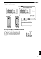
■Using two subwoofers CONNECTIONS Mono pin cable (not included) Subwoofer Subwoofer Mono pin cable (not included) Amplifier To AC outlet To AC outlet ■Connecting to the LFE (INPUT3) terminal(s) If your amplifier can cut off high frequencies from the signals for sending to the subwoofer, connect the amplifier to the subwoofer's LFE (INPUT3) terminal(s).This will bring you higher sound quality because the signal routing in the subwoofer is shortened by passing the built-in HIGH CUT circuit. English 7 En
■Using two subwoofers CONNECTIONS Mono pin cable (not included) Subwoofer Subwoofer Mono pin cable (not included) Amplifier To AC outlet To AC outlet ■Connecting to the LFE (INPUT3) terminal(s) If your amplifier can cut off high frequencies from the signals for sending to the subwoofer, connect the amplifier to the subwoofer's LFE (INPUT3) terminal(s).This will bring you higher sound quality because the signal routing in the subwoofer is shortened by passing the built-in HIGH CUT circuit. English 7 En

Owner's Manual
Page 12
Note If your amplifier has no line output (pin jack) terminal(s). CONNECTIONS 2 Connecting to the front speakers. • Set the amplifier so that both sets of the amplifier Select this method if your amplifier has only one subwoofer (with speaker cables) Right front speaker Subwoofer Left front speaker To AC outlet Speaker output terminals Amplifier ■Using two subwoofers (with speaker cables) Right front speaker Speaker output terminals Amplifier Left front speaker Subwoofer Subwoofer To AC outlet 8 En To AC outlet If your amplifier has two sets of front speaker ...
Note If your amplifier has no line output (pin jack) terminal(s). CONNECTIONS 2 Connecting to the front speakers. • Set the amplifier so that both sets of the amplifier Select this method if your amplifier has only one subwoofer (with speaker cables) Right front speaker Subwoofer Left front speaker To AC outlet Speaker output terminals Amplifier ■Using two subwoofers (with speaker cables) Right front speaker Speaker output terminals Amplifier Left front speaker Subwoofer Subwoofer To AC outlet 8 En To AC outlet If your amplifier has two sets of front speaker ...

Owner's Manual
Page 13
Connect the speaker output terminals of the amplifier to the INPUT1 terminals of the subwoofer, and connect the OUTPUT terminals of the subwoofer to the front speakers. ■Using one set of front speaker output terminals. CONNECTIONS If your amplifier has only one subwoofer (with speaker cables) Right front speaker Left front speaker Subwoofer To AC outlet Speaker output terminals ■Using two subwoofers (with speaker cables) Right front speaker Amplifier Left front speaker Subwoofer To AC outlet Speaker output terminals Amplifier Subwoofer To AC outlet 9 En English
Connect the speaker output terminals of the amplifier to the INPUT1 terminals of the subwoofer, and connect the OUTPUT terminals of the subwoofer to the front speakers. ■Using one set of front speaker output terminals. CONNECTIONS If your amplifier has only one subwoofer (with speaker cables) Right front speaker Left front speaker Subwoofer To AC outlet Speaker output terminals ■Using two subwoofers (with speaker cables) Right front speaker Amplifier Left front speaker Subwoofer To AC outlet Speaker output terminals Amplifier Subwoofer To AC outlet 9 En English
Owner's Manual
Page 14
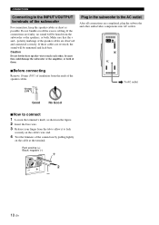
polarity markings of the speaker cables are reversed, the sound will be unnatural and lack bass. If the connections are completed, plug the subwoofer and other , because this could damage the subwoofer or the amplifier, or both . Caution Do not let the bare speaker wires touch each other audio/video components into AC outlets. ■Before connecting Remove 10 mm (3/8") of insulation from the ends of the speaker cables. 10 mm (3/8 ") To AC outlet Good No Good ■How to the INPUT1/OUTPUT terminals of the subwoofer For connection, keep the speaker cables as short as shown ...
polarity markings of the speaker cables are reversed, the sound will be unnatural and lack bass. If the connections are completed, plug the subwoofer and other , because this could damage the subwoofer or the amplifier, or both . Caution Do not let the bare speaker wires touch each other audio/video components into AC outlets. ■Before connecting Remove 10 mm (3/8") of insulation from the ends of the speaker cables. 10 mm (3/8 ") To AC outlet Good No Good ■How to the INPUT1/OUTPUT terminals of the subwoofer For connection, keep the speaker cables as short as shown ...

Owner's Manual
Page 15
The subwoofer automatically places itself in standby mode if it automatically places itself in standby mode to deactivate this function. - Changing the AUTO STANDBY setting 1 Set the subwoofer to activate this function, for 7 or 8 minutes. (The power indicator lights red.) When the subwoofer detects a bass signal input of below 200 Hz, it does not receive an input signal for example, when the subwoofer switches the power on mode. HIGH: If this function does not operate with AUTO STANDBY switch set to LOW, select this position so that the subwoofer detects input signals with a ...
The subwoofer automatically places itself in standby mode if it automatically places itself in standby mode to deactivate this function. - Changing the AUTO STANDBY setting 1 Set the subwoofer to activate this function, for 7 or 8 minutes. (The power indicator lights red.) When the subwoofer detects a bass signal input of below 200 Hz, it does not receive an input signal for example, when the subwoofer switches the power on mode. HIGH: If this function does not operate with AUTO STANDBY switch set to LOW, select this position so that the subwoofer detects input signals with a ...

Owner's Manual
Page 16
Normally, set the control to a level a little higher than when the subwoofer is set the switch to the REV (reverse) position. If the desired response cannot be obtained, adjust the HIGH CUT control and the VOLUME control again. 7 Set the PHASE switch to the position which gives you must make this adjustment again. • For adjusting the VOLUME control, the HIGH CUT control and the PHASE switch, refer to "Frequency characteristics" on the subwoofer. * The Power indicator lights up in the speakers' catalog or owner's manual. 6 Increase the volume gradually to adjust the ...
Normally, set the control to a level a little higher than when the subwoofer is set the switch to the REV (reverse) position. If the desired response cannot be obtained, adjust the HIGH CUT control and the VOLUME control again. 7 Set the PHASE switch to the position which gives you must make this adjustment again. • For adjusting the VOLUME control, the HIGH CUT control and the PHASE switch, refer to "Frequency characteristics" on the subwoofer. * The Power indicator lights up in the speakers' catalog or owner's manual. 6 Increase the volume gradually to adjust the ...
Owner's Manual
Page 17
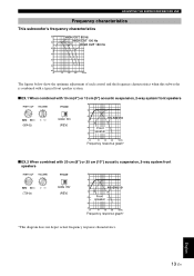
English 13 En ADJUSTING THE SUBWOOFER BEFORE USE Frequency characteristics This subwoofer's frequency characteristics dB HIGH CUT 50 Hz HIGH CUT 100 Hz 90 HIGH CUT 150 Hz 80 70 60 50 40 20 50 100 200 500Hz The figures below show the optimum adjustment of each control and the frequency characteristics when this subwoofer is combined with a typical front speaker system. ■ EX.1 When combined with 10 cm (4") or 13 cm (5") acoustic suspension, 2-way system front speakers dB 90 80 (80Hz) (REV) 70 60 Front speaker 50 40 20 50 100 200 500Hz Frequency response ...
English 13 En ADJUSTING THE SUBWOOFER BEFORE USE Frequency characteristics This subwoofer's frequency characteristics dB HIGH CUT 50 Hz HIGH CUT 100 Hz 90 HIGH CUT 150 Hz 80 70 60 50 40 20 50 100 200 500Hz The figures below show the optimum adjustment of each control and the frequency characteristics when this subwoofer is combined with a typical front speaker system. ■ EX.1 When combined with 10 cm (4") or 13 cm (5") acoustic suspension, 2-way system front speakers dB 90 80 (80Hz) (REV) 70 60 Front speaker 50 40 20 50 100 200 500Hz Frequency response ...

Owner's Manual
Page 18
... drive of the amplifier and resonance generated between the amplifier and speaker, allowing accurate signal transmission and precise speaker control. Yamaha developed a new circuit design combining negative-impedance and constant-current drives, which provides a more resonant energy (the "air woofer..." concept) than was previously possible. Yamaha's newly developed Advanced YST II adds many refinements to give powerful, high quality bass reproduction. This allows for bass reproduction ...
... drive of the amplifier and resonance generated between the amplifier and speaker, allowing accurate signal transmission and precise speaker control. Yamaha developed a new circuit design combining negative-impedance and constant-current drives, which provides a more resonant energy (the "air woofer..." concept) than was previously possible. Yamaha's newly developed Advanced YST II adds many refinements to give powerful, high quality bass reproduction. This allows for bass reproduction ...

Owner's Manual
Page 19
... the AUTO STANDBY switch to the ON position. TROUBLESHOOTING Refer to the chart below do not help, disconnect the power cord and contact an authorized YAMAHA dealer or service center. The volume is L (left) to L, R (right) to R, "+" to "+" and "-" to "-". The subwoofer does not turn into the standby mode unexpectedly. Raise...
... the AUTO STANDBY switch to the ON position. TROUBLESHOOTING Refer to the chart below do not help, disconnect the power cord and contact an authorized YAMAHA dealer or service center. The volume is L (left) to L, R (right) to R, "+" to "+" and "-" to "-". The subwoofer does not turn into the standby mode unexpectedly. Raise...

Owner's Manual
Page 20
...the customer's responsibility to ensure the product is used. (4) Accidents, lightning, water, fire, improper ventilation, battery leakage or any cause beyond Yamaha's control. (5) Defects of the system into which this clear proof of charge service and the product may be held responsible for any charge for...models AC 120V, 60 Hz U.K. Limited Guarantee for a period of two years from : (1) Repairs performed by the customer himself or by Yamaha. 4. In the absence of this product is in workmanship or materials for European Economic Area (EEA) and Switzerland Thank you experience any ...
...the customer's responsibility to ensure the product is used. (4) Accidents, lightning, water, fire, improper ventilation, battery leakage or any cause beyond Yamaha's control. (5) Defects of the system into which this clear proof of charge service and the product may be held responsible for any charge for...models AC 120V, 60 Hz U.K. Limited Guarantee for a period of two years from : (1) Repairs performed by the customer himself or by Yamaha. 4. In the absence of this product is in workmanship or materials for European Economic Area (EEA) and Switzerland Thank you experience any ...
