
Owner's Manual
Page 2
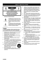
...and other instructions should be followed. 5 Water and Moisture - The unit should be used near a swimming pool, etc. 6 Carts and Stands - The power cord of time. 14 Object and Liquid Entry - Care should be situated away from the outlet when left unused for a long period of the unit...unit should be situated so that may be serviced by items placed upon or against them, paying particular attention to qualified service personnel. 17 Power Lines - The power-supply cord or the plug has been damaged; or E. All warnings on a bed, sofa, rug, or similar surface, that its ...
...and other instructions should be followed. 5 Water and Moisture - The unit should be used near a swimming pool, etc. 6 Carts and Stands - The power cord of time. 14 Object and Liquid Entry - Care should be situated away from the outlet when left unused for a long period of the unit...unit should be situated so that may be serviced by items placed upon or against them, paying particular attention to qualified service personnel. 17 Power Lines - The power-supply cord or the plug has been damaged; or E. All warnings on a bed, sofa, rug, or similar surface, that its ...

Owner's Manual
Page 3
... ELECTRICAL CODE ANTENNA LEAD IN WIRE ANTENNA DISCHARGE UNIT (NEC SECTION 810-20) GROUNDING CONDUCTORS (NEC SECTION 810-21) GROUND CLAMPS POWER SERVICE GROUNDING ELECTRODE SYSTEM (NEC ART 250. IMPORTANT : When connecting this product to eliminate the problem by using one of cable... EXAMPLE OF ANTENNA GROUNDING MAST GROUND CLAMP ELECTRIC SERVICE EQUIPMENT NEC - Follow all installations. We Want You Listening For A Lifetime YAMAHA and the Electronic Industries Association's Consumer Electronics Group want you can be connected to the grounding system of the NEC that is often...
... ELECTRICAL CODE ANTENNA LEAD IN WIRE ANTENNA DISCHARGE UNIT (NEC SECTION 810-20) GROUNDING CONDUCTORS (NEC SECTION 810-21) GROUND CLAMPS POWER SERVICE GROUNDING ELECTRODE SYSTEM (NEC ART 250. IMPORTANT : When connecting this product to eliminate the problem by using one of cable... EXAMPLE OF ANTENNA GROUNDING MAST GROUND CLAMP ELECTRIC SERVICE EQUIPMENT NEC - Follow all installations. We Want You Listening For A Lifetime YAMAHA and the Electronic Industries Association's Consumer Electronics Group want you can be connected to the grounding system of the NEC that is often...
Owner's Manual
Page 4
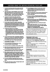
.... away from the wall outlet, grasp the plug; Using this unit with a higher voltage than specified. 13 To prevent damage by lightning, disconnect the power cord from the wall outlet. 19 VOLTAGE SELECTOR (China and General models only) The VOLTAGE SELECTOR on the surface of this unit so that this... unit in order not to a wall outlet until all connections are 110/120/220/240 V AC, 50/60 Hz. Contact qualified YAMAHA service personnel when any reasons. 16 When not planning to modify or fix this unit. - CAUTION: READ THIS BEFORE OPERATING YOUR UNIT. 1 To assure ...
.... away from the wall outlet, grasp the plug; Using this unit with a higher voltage than specified. 13 To prevent damage by lightning, disconnect the power cord from the wall outlet. 19 VOLTAGE SELECTOR (China and General models only) The VOLTAGE SELECTOR on the surface of this unit so that this... unit in order not to a wall outlet until all connections are 110/120/220/240 V AC, 50/60 Hz. Contact qualified YAMAHA service personnel when any reasons. 16 When not planning to modify or fix this unit. - CAUTION: READ THIS BEFORE OPERATING YOUR UNIT. 1 To assure ...
Owner's Manual
Page 5
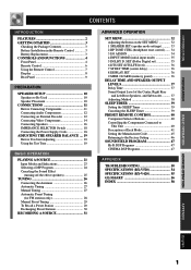
...the Factory Setting 46 SOUND FIELD PROGRAM 47 Hi-Fi DSP Programs 47 CINEMA DSP Programs 47 APPENDIX TROUBLESHOOTING 50 SPECIFICATIONS (RX-V520 54 SPECIFICATIONS (RX-V420 55 GLOSSARY 56 INDEX 58 BASIC OPERATION ADVANCED OPERATION APPENDIX English 1 SET (Dolby Digital set 35 6 DTS SET (...Connecting Audio Components 12 Connecting an External Decoder 12 Connecting Video Components 14 Connecting Speakers 16 IMPEDANCE SELECTOR Switch 18 Connecting the Power Supply Cords 18 ADJUSTING THE SPEAKER BALANCE .... 19 Before You Start Adjusting 19 Using the Test Tone 19 BASIC OPERATION ...
...the Factory Setting 46 SOUND FIELD PROGRAM 47 Hi-Fi DSP Programs 47 CINEMA DSP Programs 47 APPENDIX TROUBLESHOOTING 50 SPECIFICATIONS (RX-V520 54 SPECIFICATIONS (RX-V420 55 GLOSSARY 56 INDEX 58 BASIC OPERATION ADVANCED OPERATION APPENDIX English 1 SET (Dolby Digital set 35 6 DTS SET (...Connecting Audio Components 12 Connecting an External Decoder 12 Connecting Video Components 14 Connecting Speakers 16 IMPEDANCE SELECTOR Switch 18 Connecting the Power Supply Cords 18 ADJUSTING THE SPEAKER BALANCE .... 19 Before You Start Adjusting 19 Using the Test Tone 19 BASIC OPERATION ...

Owner's Manual
Page 6
...remote control. All rights reserved. FEATURES 5-Channel Power Amplification N Minimum RMS Output (0.06% THD, 20 Hz - 20 kHz) RX-V520 [U.S.A. "Dolby", "AC-3", "Pro Logic" and the double-D symbol are trademarks of YAMAHA DSP Technology and Dolby Digital, Dolby Pro ...models] Main: 70 W + 70 W (8 Ω) Center: 70 W (8 Ω) Rear: 70 W + 70 W (8 Ω) RX-V420 Main: 65 W + 65 W (8 Ω) Center: 65 W (8 Ω) Rear: 65 W + 65 W (8 Ω) N Maximum Power (EIAJ) (10% THD, 1 kHz) RX-V520 [China and General models] Main: 100 W + 100 W (8 Ω) Center: 100 W (8 Ω) Rear: 100 W +...
...remote control. All rights reserved. FEATURES 5-Channel Power Amplification N Minimum RMS Output (0.06% THD, 20 Hz - 20 kHz) RX-V520 [U.S.A. "Dolby", "AC-3", "Pro Logic" and the double-D symbol are trademarks of YAMAHA DSP Technology and Dolby Digital, Dolby Pro ...models] Main: 70 W + 70 W (8 Ω) Center: 70 W (8 Ω) Rear: 70 W + 70 W (8 Ω) RX-V420 Main: 65 W + 65 W (8 Ω) Center: 65 W (8 Ω) Rear: 65 W + 65 W (8 Ω) N Maximum Power (EIAJ) (10% THD, 1 kHz) RX-V520 [China and General models] Main: 100 W + 100 W (8 Ω) Center: 100 W (8 Ω) Rear: 100 W +...
Owner's Manual
Page 8
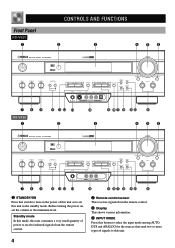
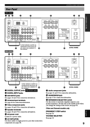
... PHONES S VIDEO VIDEO L AUDIO R OPTICAL A/B/C/D/E PRESET /TUNING FM/AM EDIT MEMORY TUNING MODE MAN'L/AUTO FM AUTO/MAN'L MONO INPUT MODE INPUT 6CH INPUT 789 RX-V420 1 SILENT 0 qw e 2 VIDEO AUX r t yu i op a 3 456 STANDBY /ON D I G I TA L SURROUND BASS TREBLE BALANCE -+ -+ L R SPEAKERS A B ON OFF D I G I TA...7 8 9 0 qw e r t yu i op a 1 STANDBY/ON Press this switch to turn on , set this unit. 4 Before turning the power on the power of signals to set the volume at the minimum level. Standby mode In this mode, this unit consumes a very small quantity of...
... PHONES S VIDEO VIDEO L AUDIO R OPTICAL A/B/C/D/E PRESET /TUNING FM/AM EDIT MEMORY TUNING MODE MAN'L/AUTO FM AUTO/MAN'L MONO INPUT MODE INPUT 6CH INPUT 789 RX-V420 1 SILENT 0 qw e 2 VIDEO AUX r t yu i op a 3 456 STANDBY /ON D I G I TA L SURROUND BASS TREBLE BALANCE -+ -+ L R SPEAKERS A B ON OFF D I G I TA...7 8 9 0 qw e r t yu i op a 1 STANDBY/ON Press this switch to turn on , set this unit. 4 Before turning the power on the power of signals to set the volume at the minimum level. Standby mode In this mode, this unit consumes a very small quantity of...

Owner's Manual
Page 10
...(TUNER) on the remote control. A/B/C/D/E: To select one of these buttons which corresponds to the component you press this button, the unit switches between the power on and standby mode. 4 TEST Press this button to output the test tone for full details. 1 Press AMP(TUNER). 2 3 q w 4 e 5 6 TV VOLUME 7 8...the Manufacturer Code".) When the component selector button has been pressed, the remote control is set to that component operation mode. 3 POWER Each time you want to the 6CH INPUT jacks. 6 CONTROLS AND FUNCTIONS Remote Control This section describes basic operation of this ...
...(TUNER) on the remote control. A/B/C/D/E: To select one of these buttons which corresponds to the component you press this button, the unit switches between the power on and standby mode. 4 TEST Press this button to output the test tone for full details. 1 Press AMP(TUNER). 2 3 q w 4 e 5 6 TV VOLUME 7 8...the Manufacturer Code".) When the component selector button has been pressed, the remote control is set to that component operation mode. 3 POWER Each time you want to the 6CH INPUT jacks. 6 CONTROLS AND FUNCTIONS Remote Control This section describes basic operation of this ...
Owner's Manual
Page 13
...(REC) MD/CD-R DVD D-TV/CBL AUDIO SIGNAL R IN OUT VCR 1 SUB WOOFER OUTPUT R+ A SPEAKERS - - +L MAIN B CENTER REAR R (SURROUND) L + - TOTAL 9 RX-V420 As this switch (see page 18). IMPEDANCE SELECTOR SET BEFORE POWER ON MAIN A OR B: 8 MIN. /SPEAKER A + B:16 MIN. /SPEAKER CENTER : 8 MIN. /SPEAKER REAR : 8 MIN. /SPEAKER MAIN A OR B: 4 MIN. /SPEAKER A + B: 8 MIN. /SPEAKER...
...(REC) MD/CD-R DVD D-TV/CBL AUDIO SIGNAL R IN OUT VCR 1 SUB WOOFER OUTPUT R+ A SPEAKERS - - +L MAIN B CENTER REAR R (SURROUND) L + - TOTAL 9 RX-V420 As this switch (see page 18). IMPEDANCE SELECTOR SET BEFORE POWER ON MAIN A OR B: 8 MIN. /SPEAKER A + B:16 MIN. /SPEAKER CENTER : 8 MIN. /SPEAKER REAR : 8 MIN. /SPEAKER MAIN A OR B: 4 MIN. /SPEAKER A + B: 8 MIN. /SPEAKER...
Owner's Manual
Page 14
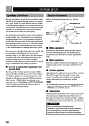
...the front face of your TV monitor. Sometimes a video monitor may not shift smoothly. If for the center speaker and the rear speakers. The YAMAHA Active Servo Processing Subwoofer System is not practical to use of a subwoofer is for reproducing the LFE (low frequency effect) channel with high fidelity when... of the center speaker with a 5-speaker system, using main speakers, rear speakers and a center speaker. We recommend that can do not have enough power-handling capacity to ensure even tonal quality. I Main speakers Place the right and left main speakers.
...the front face of your TV monitor. Sometimes a video monitor may not shift smoothly. If for the center speaker and the rear speakers. The YAMAHA Active Servo Processing Subwoofer System is not practical to use of a subwoofer is for reproducing the LFE (low frequency effect) channel with high fidelity when... of the center speaker with a 5-speaker system, using main speakers, rear speakers and a center speaker. We recommend that can do not have enough power-handling capacity to ensure even tonal quality. I Main speakers Place the right and left main speakers.
Owner's Manual
Page 15
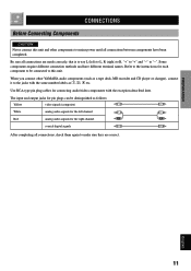
... 11 The input and output jacks for pin plugs can be connected to this unit and other YAMAHA audio components (such as a tape deck, MD recorder and CD player or changer), connect it to mains power until all connections, check them again to make sure they are made correctly, that is to...
... 11 The input and output jacks for pin plugs can be connected to this unit and other YAMAHA audio components (such as a tape deck, MD recorder and CD player or changer), connect it to mains power until all connections, check them again to make sure they are made correctly, that is to...

Owner's Manual
Page 16
... I /O ASSIGN" in place. I Connecting to digital jacks This unit has digital jacks for 96-kHz sampling digital signals. • RX-V420 only When making connections between the digital signal jacks, you should connect the components to the same-named analog audio signal jacks of this unit... surround channels. CONNECTIONS Connecting Audio Components I Connecting an MD recorder, CD recorder or tape deck y • RX-V520 only When you connect a recording component to this unit, keep its power on while using "3 I Connecting a CD player y • The COAXIAL jack is output only to the digital...
... I /O ASSIGN" in place. I Connecting to digital jacks This unit has digital jacks for 96-kHz sampling digital signals. • RX-V420 only When making connections between the digital signal jacks, you should connect the components to the same-named analog audio signal jacks of this unit... surround channels. CONNECTIONS Connecting Audio Components I Connecting an MD recorder, CD recorder or tape deck y • RX-V520 only When you connect a recording component to this unit, keep its power on while using "3 I Connecting a CD player y • The COAXIAL jack is output only to the digital...
Owner's Manual
Page 21
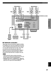
... channels are assigned to this jack. APPENDIX English 17 SET)" and "6 DTS SET" in amplifier, including the YAMAHA Active Servo Processing Subwoofer System, connect the input jack of the subwoofer system to the operation instructions for the subwoofer....) • Depending on the settings of "1 SPEAKER SET", "LFE LEVEL (5 DOLBY D. Notes • Adjust the subwoofer volume according to this jack. TOTAL Left (RX-V520/U.S.A. IMPEDANCE SELECTOR SET BEFORE POWER ON MAIN A OR B: 8 MIN. /SPEAKER A + B:16 MIN. /SPEAKER CENTER : 8 MIN. /SPEAKER REAR : 8 MIN. /SPEAKER MAIN A OR B: 4...
... channels are assigned to this jack. APPENDIX English 17 SET)" and "6 DTS SET" in amplifier, including the YAMAHA Active Servo Processing Subwoofer System, connect the input jack of the subwoofer system to the operation instructions for the subwoofer....) • Depending on the settings of "1 SPEAKER SET", "LFE LEVEL (5 DOLBY D. Notes • Adjust the subwoofer volume according to this jack. TOTAL Left (RX-V520/U.S.A. IMPEDANCE SELECTOR SET BEFORE POWER ON MAIN A OR B: 8 MIN. /SPEAKER A + B:16 MIN. /SPEAKER CENTER : 8 MIN. /SPEAKER REAR : 8 MIN. /SPEAKER MAIN A OR B: 4...

Owner's Manual
Page 22
... turned on. Select the right or left position according to the impedance of speakers in the standby mode. (RX-V520/General model) IMPEDANCE SELECTOR IMPEDANCE SELECTOR SET BEFORE POWER ON MAIN A OR B: 8 MIN. /SPEAKER A + B:16 MIN. /SPEAKER CENTER : 8 MIN. /SPEAKER REAR : 8 MIN. /SPEAKER MAIN A OR B: ...: 6 MIN. /SPEAKER REAR : 6 MIN. /SPEAKER AC OUTLETS SWITCHED 100W MAX. If so, slide the switch to an AC power outlet. I AC OUTLETS (SWITCHED) (RX-V520/U.S.A. The impedance of each speaker must be set of main speakers, the impedance of each speaker must be 6 Ω or higher...
... turned on. Select the right or left position according to the impedance of speakers in the standby mode. (RX-V520/General model) IMPEDANCE SELECTOR IMPEDANCE SELECTOR SET BEFORE POWER ON MAIN A OR B: 8 MIN. /SPEAKER A + B:16 MIN. /SPEAKER CENTER : 8 MIN. /SPEAKER REAR : 8 MIN. /SPEAKER MAIN A OR B: ...: 6 MIN. /SPEAKER REAR : 6 MIN. /SPEAKER AC OUTLETS SWITCHED 100W MAX. If so, slide the switch to an AC power outlet. I AC OUTLETS (SWITCHED) (RX-V520/U.S.A. The impedance of each speaker must be set of main speakers, the impedance of each speaker must be 6 Ω or higher...
Owner's Manual
Page 23
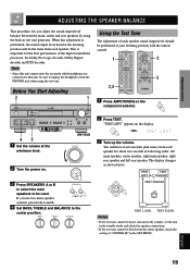
... left rear speaker. APPENDIX English 19 "TEST LEFT" appears on the component selector. 2 Press TEST. You will be performed at the minimum level. (RX-V520) VOLUME 2 Turn the power on. INTRODUCTION PREPARATION BASIC OPERATION ADVANCED OPERATION ADJUSTING THE SPEAKER BALANCE This procedure lets you use two main speaker systems, press both A and...
... left rear speaker. APPENDIX English 19 "TEST LEFT" appears on the component selector. 2 Press TEST. You will be performed at the minimum level. (RX-V520) VOLUME 2 Turn the power on. INTRODUCTION PREPARATION BASIC OPERATION ADVANCED OPERATION ADJUSTING THE SPEAKER BALANCE This procedure lets you use two main speaker systems, press both A and...
Owner's Manual
Page 25
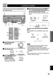
...VIDEO L AUDIO R OPTICAL A/B/C/D/E PRESET /TUNING FM/AM EDIT MEMORY TUNING MODE MAN'L/AUTO FM AUTO/MAN'L MONO INPUT MODE INPUT 6CH INPUT SILENT VIDEO AUX 7 (RX-V520) 4 6 2 4 7 4 Select the desired input source with INPUT l / h (or the input selector buttons). (Turn on the video monitor for details...INPUT" appears on the display. 6CH INPUT or Front panel Remote control 1 Set the volume at the VOLUME minimum level. 2 Turn the power on the display. INPUT or Front panel Remote control Input source To select a source connected to "Input Modes and Indications" on page 23 ...
...VIDEO L AUDIO R OPTICAL A/B/C/D/E PRESET /TUNING FM/AM EDIT MEMORY TUNING MODE MAN'L/AUTO FM AUTO/MAN'L MONO INPUT MODE INPUT 6CH INPUT SILENT VIDEO AUX 7 (RX-V520) 4 6 2 4 7 4 Select the desired input source with INPUT l / h (or the input selector buttons). (Turn on the video monitor for details...INPUT" appears on the display. 6CH INPUT or Front panel Remote control 1 Set the volume at the VOLUME minimum level. 2 Turn the power on the display. INPUT or Front panel Remote control Input source To select a source connected to "Input Modes and Indications" on page 23 ...
Owner's Manual
Page 26
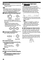
...for the source component (and "TUNING" for the player.) Note the following indication will be controlled with the input selector buttons on the digital signal RX-V520 only The digital input jacks of the output volume from a video source with INPUT l / h on the remote control. DSP programs cannot ...• If "MAIN SP" in the standby mode. Adjustment of the subwoofer) I When you have finished using this unit Press STANDBY/ON (or POWER) to set this , use a source that supports 96-kHz sampling digital signals and set to BOTH, the sound is input to this when you ...
...for the source component (and "TUNING" for the player.) Note the following indication will be controlled with the input selector buttons on the digital signal RX-V520 only The digital input jacks of the output volume from a video source with INPUT l / h on the remote control. DSP programs cannot ...• If "MAIN SP" in the standby mode. Adjustment of the subwoofer) I When you have finished using this unit Press STANDBY/ON (or POWER) to set this , use a source that supports 96-kHz sampling digital signals and set to BOTH, the sound is input to this when you ...
Owner's Manual
Page 28
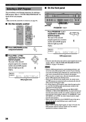
... S VIDEO VIDEO L AUDIO R OPTICAL A/B/C/D/E PRESET /TUNING FM/AM EDIT MEMORY TUNING MODE MAN'L/AUTO FM AUTO/MAN'L MONO INPUT MODE INPUT 6CH INPUT (RX-V520) SILENT VIDEO AUX PROGRAM / Press PROGRAM l or h repeatedly to select the desired program. DIGITAL DSP MOVIE THEATER 1 BASS EXT. The name of.... (Refer to "DELAY TIME AND SPEAKER OUTPUT LEVELS" on page 37 for a moment and the selected DSP program indicator lights up on the power again. • If a Dolby Digital or DTS signal is input when the input mode is reproduced as normal 2-channel stereo. 24 DIGITAL DSP...
... S VIDEO VIDEO L AUDIO R OPTICAL A/B/C/D/E PRESET /TUNING FM/AM EDIT MEMORY TUNING MODE MAN'L/AUTO FM AUTO/MAN'L MONO INPUT MODE INPUT 6CH INPUT (RX-V520) SILENT VIDEO AUX PROGRAM / Press PROGRAM l or h repeatedly to select the desired program. DIGITAL DSP MOVIE THEATER 1 BASS EXT. The name of.... (Refer to "DELAY TIME AND SPEAKER OUTPUT LEVELS" on page 37 for a moment and the selected DSP program indicator lights up on the power again. • If a Dolby Digital or DTS signal is input when the input mode is reproduced as normal 2-channel stereo. 24 DIGITAL DSP...
Owner's Manual
Page 29
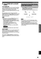
...it may happen that case, turn the sound effect back on the sound effect. This feature delivers powerful surround reproduction just as the input source; - Note • This unit is not set to ... on the SET MENU to cancel the sound effect and monitor only the main sound. RX-V520 only when 96-kHz sampling digital signals are on the source. when the sound ... selected as if listening through the generation of the DSP program without rear speakers. Using YAMAHA original technology, natural surround reproduction is performed by connecting your headphones to the PHONES jack ...
...it may happen that case, turn the sound effect back on the sound effect. This feature delivers powerful surround reproduction just as the input source; - Note • This unit is not set to ... on the SET MENU to cancel the sound effect and monitor only the main sound. RX-V520 only when 96-kHz sampling digital signals are on the source. when the sound ... selected as if listening through the generation of the DSP program without rear speakers. Using YAMAHA original technology, natural surround reproduction is performed by connecting your headphones to the PHONES jack ...
Owner's Manual
Page 30
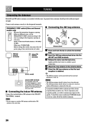
... from the AC outlet. North, Central and South America: 100 kHz/ 10 kHz Other area: 50 kHz/9 kHz Before setting this switch, disconnect the AC power plug of this unit. y • The AM loop antenna can be removed from this unit. I Connecting the AM loop antenna 31 4 25 Antenna stand 1 Press.... Connect each antenna correctly to lock the lead wires. A good earth ground is connected to the FM ANT 75Ω UNBAL. Consult the nearest authorized YAMAHA dealer or service center about the outdoor antennas. 26
... from the AC outlet. North, Central and South America: 100 kHz/ 10 kHz Other area: 50 kHz/9 kHz Before setting this switch, disconnect the AC power plug of this unit. y • The AM loop antenna can be removed from this unit. I Connecting the AM loop antenna 31 4 25 Antenna stand 1 Press.... Connect each antenna correctly to lock the lead wires. A good earth ground is connected to the FM ANT 75Ω UNBAL. Consult the nearest authorized YAMAHA dealer or service center about the outdoor antennas. 26
Owner's Manual
Page 32
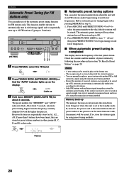
...of preset stations by following the procedure in with strong signals and to sequentially store up to E8. 2. If, however, the power cord is disconnected from the frequency currently displayed toward the higher frequencies. If more than 8 stations have all stations. •...stations again by using preset tuning methods. 28 STANDBY /ON D I G I TA L SURROUND BASS TREBLE BALANCE -+ -+ L R SPEAKERS A B ON OFF (RX-V520) D I G I When automatic preset tuning is completed The display shows the frequency of the last preset station. Received stations are stored as A1, A2 ...
...of preset stations by following the procedure in with strong signals and to sequentially store up to E8. 2. If, however, the power cord is disconnected from the frequency currently displayed toward the higher frequencies. If more than 8 stations have all stations. •...stations again by using preset tuning methods. 28 STANDBY /ON D I G I TA L SURROUND BASS TREBLE BALANCE -+ -+ L R SPEAKERS A B ON OFF (RX-V520) D I G I When automatic preset tuning is completed The display shows the frequency of the last preset station. Received stations are stored as A1, A2 ...


