User Guide
Page 2
... be properties of others. Operation is subject to Part 15 of the FCC rules. These limits are used in any products, or software described herein. BPS-120 User's Guide 1. ZyXEL further reserves the right to comply with the limits for identification purposes only and may not cause harmful interference. (2) This switch must accept any license under its patent rights...
... be properties of others. Operation is subject to Part 15 of the FCC rules. These limits are used in any products, or software described herein. BPS-120 User's Guide 1. ZyXEL further reserves the right to comply with the limits for identification purposes only and may not cause harmful interference. (2) This switch must accept any license under its patent rights...

User Guide
Page 3
... equipment will be extended by the user to the product page at his own expense. BPS-120 User's Guide radio communications. Taiwanese BSMI (Bureau of this equipment, users should be aware that the compliance with a single line individual service may not prevent degradation of connection. Operation of Standards, Metrology and Inspection) A Warning: Certifications Refer to this product may cause radio...
... equipment will be extended by the user to the product page at his own expense. BPS-120 User's Guide radio communications. Taiwanese BSMI (Bureau of this equipment, users should be aware that the compliance with a single line individual service may not prevent degradation of connection. Operation of Standards, Metrology and Inspection) A Warning: Certifications Refer to this product may cause radio...

User Guide
Page 4
... necessary to restore the product or components to proper operating condition. NOTE Repair or replacement, as appropriate. ZyXEL shall in lieu of all other rights that this warranty, contact ZyXEL's Service Center for parts and labor. This warranty is in no event be shipped by an act of this product is the exclusive remedy of ZyXEL. BPS-120 User's Guide Users should not...
... necessary to restore the product or components to proper operating condition. NOTE Repair or replacement, as appropriate. ZyXEL shall in lieu of all other rights that this warranty, contact ZyXEL's Service Center for parts and labor. This warranty is in no event be shipped by an act of this product is the exclusive remedy of ZyXEL. BPS-120 User's Guide Users should not...
User Guide
Page 5
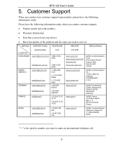
....us.zyxel.com ftp.us.zyxel.com ZyXEL Communications Inc. 1130 N. BPS-120 User's Guide 5. Miller St. Anaheim CA 92806-2001 U.S.A. Adenauerstr. 20/A2 D-52146 Wuerselen Germany ZyXEL France 1 rue des Vergers Bat. 1 / C 69760 Limonest France SPAIN support@zyxel.es sales@zyxel.es +34 902 195 420 +34 913 005 345 www.zyxel.es ZyXEL Communications Alejandro Villegas 33 1º, 28043 Madrid Spain 1 "+" is the (prefix) number...
....us.zyxel.com ftp.us.zyxel.com ZyXEL Communications Inc. 1130 N. BPS-120 User's Guide 5. Miller St. Anaheim CA 92806-2001 U.S.A. Adenauerstr. 20/A2 D-52146 Wuerselen Germany ZyXEL France 1 rue des Vergers Bat. 1 / C 69760 Limonest France SPAIN support@zyxel.es sales@zyxel.es +34 902 195 420 +34 913 005 345 www.zyxel.es ZyXEL Communications Alejandro Villegas 33 1º, 28043 Madrid Spain 1 "+" is the (prefix) number...
User Guide
Page 7
BPS-120 User's Guide Table of Contents 1 Introducing the BPS-120 9 2 Hardware Installation and Connections 9 2.1 Desktop Installation 10 2.2 Rack-mounted Installation 10 2.3 Attaching Power Cables and Connector Definition 12 2.4 Front Panel and LED Displays 14 3 Troubleshooting 18 7
BPS-120 User's Guide Table of Contents 1 Introducing the BPS-120 9 2 Hardware Installation and Connections 9 2.1 Desktop Installation 10 2.2 Rack-mounted Installation 10 2.3 Attaching Power Cables and Connector Definition 12 2.4 Front Panel and LED Displays 14 3 Troubleshooting 18 7

User Guide
Page 9
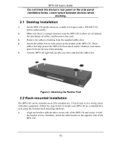
... facilitates rack mounting and high-density deployment. 2 Hardware Installation and Connections 9 BPS-120 User's Guide 1 Introducing the BPS-120 The BPS-120 is a backup power system to which you can supply power to a device that have a 12VDC external backup power supply connector. Figure 1 BPS-120 Backup Power System The BPS-120 has the following features: • Six (6) output power ports for connecting devices. • Individual front-panel LEDs to show status for each output power port, internal power hardware, internal fans, and internal temperature. • Fast power switchover...
... facilitates rack mounting and high-density deployment. 2 Hardware Installation and Connections 9 BPS-120 User's Guide 1 Introducing the BPS-120 The BPS-120 is a backup power system to which you can supply power to a device that have a 12VDC external backup power supply connector. Figure 1 BPS-120 Backup Power System The BPS-120 has the following features: • Six (6) output power ports for connecting devices. • Individual front-panel LEDs to show status for each output power port, internal power hardware, internal fans, and internal temperature. • Fast power switchover...
User Guide
Page 10
... power outlet nearby. 2. Turn the BPS-120 right-side up after you have attached the rubber feet. BPS-120 User's Guide Do not block the device's rear panel or the side panel ventilation holes. Similarly, attach the other equipment. Figure 2: Attaching the Rubber Feet 2.2 Rack-mounted Installation The BPS-120 can be mounted on a standard EIA rack using the included rack-mounting hardware. 1. Leave space between devices when stacking. 2.1 Desktop Installation...
... power outlet nearby. 2. Turn the BPS-120 right-side up after you have attached the rubber feet. BPS-120 User's Guide Do not block the device's rear panel or the side panel ventilation holes. Similarly, attach the other equipment. Figure 2: Attaching the Rubber Feet 2.2 Rack-mounted Installation The BPS-120 can be mounted on a standard EIA rack using the included rack-mounting hardware. 1. Leave space between devices when stacking. 2.1 Desktop Installation...
User Guide
Page 11
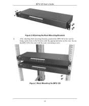
Secure the BPS-120 to the rack with the appropriate holes on the rack. BPS-120 User's Guide Figure 2 Attaching the Rack Mounting Brackets 2. After attaching both mounting brackets, position the BPS-120 in the rack by lining up the holes in the brackets with the rack's mounting screws. Figure 3 Rack Mounting the BPS-120 11
Secure the BPS-120 to the rack with the appropriate holes on the rack. BPS-120 User's Guide Figure 2 Attaching the Rack Mounting Brackets 2. After attaching both mounting brackets, position the BPS-120 in the rack by lining up the holes in the brackets with the rack's mounting screws. Figure 3 Rack Mounting the BPS-120 11

User Guide
Page 12
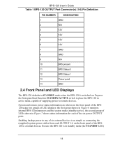
... 3-6, etc. There is supplied based upon output port priority, with OUTPUT 1 having the highest priority. The rear connector pin-out diagram and power signal descriptions are keyed for up see Table 5 for troubleshooting information. Backup power for OUTPUTs (1-6). BPS-120 User's Guide 2.3 Attaching Power Cables and Connector Definition The BPS-120 includes power connections for one way. The STANDBY, PWR, TEMP, and FAN LEDs will then light on the rear panel...
... 3-6, etc. There is supplied based upon output port priority, with OUTPUT 1 having the highest priority. The rear connector pin-out diagram and power signal descriptions are keyed for up see Table 5 for troubleshooting information. Backup power for OUTPUTs (1-6). BPS-120 User's Guide 2.3 Attaching Power Cables and Connector Definition The BPS-120 includes power connections for one way. The STANDBY, PWR, TEMP, and FAN LEDs will then light on the rear panel...
User Guide
Page 13
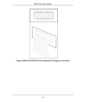
BPS-120 User's Guide Figure 5 BPS-120 OUTPUT Port Connector Pin Diagram, and Cable 13
BPS-120 User's Guide Figure 5 BPS-120 OUTPUT Port Connector Pin Diagram, and Cable 13
User Guide
Page 14
... (supplied) system power cables from each OUTPUT 1-6 on the front panel of the BPS120 using two groups of LED displays: the first group shown in Figure 6 monitors internal BPS-120 parameters and the system mode (standby/active), the second group of LEDs shown in Figure 7 shows status information for each of six external devices is switched on. BPS-120 User's Guide Table 1 BPS-120 OUTPUT Port Connector(s) (1-6) Pin Definition PIN NUMBER...
... (supplied) system power cables from each OUTPUT 1-6 on the front panel of the BPS120 using two groups of LED displays: the first group shown in Figure 6 monitors internal BPS-120 parameters and the system mode (standby/active), the second group of LEDs shown in Figure 7 shows status information for each of six external devices is switched on. BPS-120 User's Guide Table 1 BPS-120 OUTPUT Port Connector(s) (1-6) Pin Definition PIN NUMBER...

User Guide
Page 15
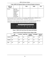
... STANDBY mode. GREEN: The BPS-120 internal temperature is functioning normally. Table 2 BPS-120 System States and Internal System Indicators BPS-120 STATE ACTIVE On: The BPS-120 is described in Figure 6. STANDBY On: The BPS-120 is functioning normally; RED: The BPS-120 has an internal overtemperature problem. PWR TEMP FAN GREEN: The BPS-120 internal power module is within normal limits. GREEN: The BPS120 internal fans are not operating properly. 15 BPS-120 User's Guide should light...
... STANDBY mode. GREEN: The BPS-120 internal temperature is functioning normally. Table 2 BPS-120 System States and Internal System Indicators BPS-120 STATE ACTIVE On: The BPS-120 is described in Figure 6. STANDBY On: The BPS-120 is functioning normally; RED: The BPS-120 has an internal overtemperature problem. PWR TEMP FAN GREEN: The BPS-120 internal power module is within normal limits. GREEN: The BPS120 internal fans are not operating properly. 15 BPS-120 User's Guide should light...
User Guide
Page 16
... 7 and Table 3 and Table 4. Each rear panel OUTPUT port has a corresponding (GREEN, RED, AMBER) LED to ensure externally connected systems are operating normally. BPS-120 User's Guide Table 2 BPS-120 System States and Internal System Indicators BPS-120 STATE PWR TEMP FAN FAULT On: The BPS-120 has detected an internal system problem or external power fault. Figure 7 BPS-120 Front Panel DC Output LED Detail Table 3 Front Panel DC Output Power Output LEDs GREEN NO CONNECTION Off ACTIVE...
... 7 and Table 3 and Table 4. Each rear panel OUTPUT port has a corresponding (GREEN, RED, AMBER) LED to ensure externally connected systems are operating normally. BPS-120 User's Guide Table 2 BPS-120 System States and Internal System Indicators BPS-120 STATE PWR TEMP FAN FAULT On: The BPS-120 has detected an internal system problem or external power fault. Figure 7 BPS-120 Front Panel DC Output LED Detail Table 3 Front Panel DC Output Power Output LEDs GREEN NO CONNECTION Off ACTIVE...
User Guide
Page 17
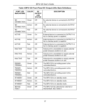
BPS-120 User's Guide Table 4 BPS-120 Front Panel DC Output LEDs State Definitions PORT LED INDICATIONS COLOR DC OUTPUT LED STATUS DESCRIPTION NO Green Off CONNECTION No external device is connected to the connected device. ACTIVE Amber Off External device is connected to supply external power because another is supplied. INACTIVE Red Off Output port is unavailable to OUTPUT1-6 but no backup power is in use . STANDBY Red Off The BPS-120 is supplied. INACTIVE Green On Output port is...
BPS-120 User's Guide Table 4 BPS-120 Front Panel DC Output LEDs State Definitions PORT LED INDICATIONS COLOR DC OUTPUT LED STATUS DESCRIPTION NO Green Off CONNECTION No external device is connected to the connected device. ACTIVE Amber Off External device is connected to supply external power because another is supplied. INACTIVE Red Off Output port is unavailable to OUTPUT1-6 but no backup power is in use . STANDBY Red Off The BPS-120 is supplied. INACTIVE Green On Output port is...
User Guide
Page 18
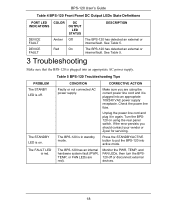
... . The BPS-120 has an internal hardware system fault (PWR, TEMP, or FAN LEDs are using the rear panel switch. BPS-120 User's Guide Table 4 BPS-120 Front Panel DC Output LEDs State Definitions PORT LED INDICATIONS COLOR DC OUTPUT LED STATUS DESCRIPTION DEVICE FAULT Amber Off The BPS-120 has detected an external or internal fault. Table 5 BPS-120 Troubleshooting Tips PROBLEM The STANBY LED is in again. CONDITION CORRECTIVE ACTION Faulty or not connected AC power supply. The BPS-120 is...
... . The BPS-120 has an internal hardware system fault (PWR, TEMP, or FAN LEDs are using the rear panel switch. BPS-120 User's Guide Table 4 BPS-120 Front Panel DC Output LEDs State Definitions PORT LED INDICATIONS COLOR DC OUTPUT LED STATUS DESCRIPTION DEVICE FAULT Amber Off The BPS-120 has detected an external or internal fault. Table 5 BPS-120 Troubleshooting Tips PROBLEM The STANBY LED is in again. CONDITION CORRECTIVE ACTION Faulty or not connected AC power supply. The BPS-120 is...

User Guide
Page 19
... power is defective. If the problem persists replace the BPS-120. The TEMP LED is defective or the BPS-120 has detected an overcurrent. CORRECTIVE ACTION The internal power supply is red. BPS-120 User's Guide Table 5 BPS-120 Troubleshooting Tips PROBLEM The PWR LED is red. BPS-120 internal temperature has exceeded limit. If the FAULT LED does not turn off and the PWR LED does not turn green, cycle the power on the BPS-120 using the rear panel switch...
... power is defective. If the problem persists replace the BPS-120. The TEMP LED is defective or the BPS-120 has detected an overcurrent. CORRECTIVE ACTION The internal power supply is red. BPS-120 User's Guide Table 5 BPS-120 Troubleshooting Tips PROBLEM The PWR LED is red. BPS-120 internal temperature has exceeded limit. If the FAULT LED does not turn off and the PWR LED does not turn green, cycle the power on the BPS-120 using the rear panel switch...
User Guide
Page 20
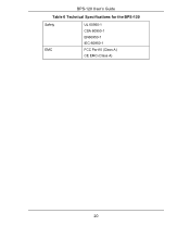
BPS-120 User's Guide Table 6 Technical Specifications for the BPS-120 Safety EMC UL 60950-1 CSA 60950-1 EN60950-1 IEC-60950-1 FCC Part15 (Class A) CE EMC (Class A) 20
BPS-120 User's Guide Table 6 Technical Specifications for the BPS-120 Safety EMC UL 60950-1 CSA 60950-1 EN60950-1 IEC-60950-1 FCC Part15 (Class A) CE EMC (Class A) 20


