User Guide
Page 7
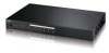
BPS-120 User's Guide Table of Contents 1 Introducing the BPS-120 9 2 Hardware Installation and Connections 9 2.1 Desktop Installation 10 2.2 Rack-mounted Installation 10 2.3 Attaching Power Cables and Connector Definition 12 2.4 Front Panel and LED Displays 14 3 Troubleshooting 18 7
BPS-120 User's Guide Table of Contents 1 Introducing the BPS-120 9 2 Hardware Installation and Connections 9 2.1 Desktop Installation 10 2.2 Rack-mounted Installation 10 2.3 Attaching Power Cables and Connector Definition 12 2.4 Front Panel and LED Displays 14 3 Troubleshooting 18 7

User Guide
Page 12
...12 There is supplied based upon output port priority, with OUTPUT 1 having the highest priority. Backup power for externally connected devices is no need to OUTPUTs 2-6. OUTPUT 2 has backup power priority over devices connected to worry about inserting the power cables incorrectly as switches or routers. BPS-120... User's Guide 2.3 Attaching Power Cables and Connector Definition The BPS-120 includes power connections for up see Table 5 for troubleshooting information. The power ...
...12 There is supplied based upon output port priority, with OUTPUT 1 having the highest priority. Backup power for externally connected devices is no need to OUTPUTs 2-6. OUTPUT 2 has backup power priority over devices connected to worry about inserting the power cables incorrectly as switches or routers. BPS-120... User's Guide 2.3 Attaching Power Cables and Connector Definition The BPS-120 includes power connections for up see Table 5 for troubleshooting information. The power ...
User Guide
Page 14
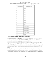
... Connector(s) (1-6) Pin Definition PIN NUMBER DESIGNATION 1 GND 2 N/A 3 12V 4 12V 5 12V 6 12V 7 GND 8 GND 9 N/A 10 BPS present 11 BPS Status0 12 BPS Status1 13 Power good 14 GND 2.4 Front Panel and LED Displays The BPS-120 defaults to STANDBY mode when the BPS-120 is switched on the front panel of the BPS120 using two groups of LED displays...
... Connector(s) (1-6) Pin Definition PIN NUMBER DESIGNATION 1 GND 2 N/A 3 12V 4 12V 5 12V 6 12V 7 GND 8 GND 9 N/A 10 BPS present 11 BPS Status0 12 BPS Status1 13 Power good 14 GND 2.4 Front Panel and LED Displays The BPS-120 defaults to STANDBY mode when the BPS-120 is switched on the front panel of the BPS120 using two groups of LED displays...

User Guide
Page 19
... unavailable or not operating properly. Reduce the ambient temperature. Table 6 Technical Specifications for the BPS-120 AC Input Voltage 100 - 240 VAC, 50/60 Hz Power Overload protection (power module fuse) 1.8A Max internal universal power supply 120 W per port 12 VDC output Operating Temperature Storage Temperature Power consumption 180W maximum (AC) 0o C ~ 45o...
... unavailable or not operating properly. Reduce the ambient temperature. Table 6 Technical Specifications for the BPS-120 AC Input Voltage 100 - 240 VAC, 50/60 Hz Power Overload protection (power module fuse) 1.8A Max internal universal power supply 120 W per port 12 VDC output Operating Temperature Storage Temperature Power consumption 180W maximum (AC) 0o C ~ 45o...