
User Guide
Page 9
The BPS-120 monitors the power status of ZyXEL's devices that have a 12VDC external backup power supply connector. Figure 1 BPS-120 Backup Power System The BPS-120 has the following features: • Six (6) output power ports for connecting devices. • Individual front-panel LEDs to show status for each output power port, internal power hardware, internal fans, and internal temperature. • Fast power switchover ensures that a power failure...
The BPS-120 monitors the power status of ZyXEL's devices that have a 12VDC external backup power supply connector. Figure 1 BPS-120 Backup Power System The BPS-120 has the following features: • Six (6) output power ports for connecting devices. • Individual front-panel LEDs to show status for each output power port, internal power hardware, internal fans, and internal temperature. • Fast power switchover ensures that a power failure...

User Guide
Page 12
... switch on the rear panel from the "0" to six (6) external devices. BPS-120 User's Guide 2.3 Attaching Power Cables and Connector Definition The BPS-120 includes power connections for one way. There is , an external device connected to OUTPUT 1 has backup power priority over devices connected to OUTPUTs 2-6. Backup power is supplied based upon output port priority, with OUTPUT 1 having the...
... switch on the rear panel from the "0" to six (6) external devices. BPS-120 User's Guide 2.3 Attaching Power Cables and Connector Definition The BPS-120 includes power connections for one way. There is , an external device connected to OUTPUT 1 has backup power priority over devices connected to OUTPUTs 2-6. Backup power is supplied based upon output port priority, with OUTPUT 1 having the...
User Guide
Page 14
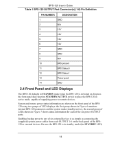
... LED) 14 BPS-120 User's Guide Table 1 BPS-120 OUTPUT Port Connector(s) (1-6) Pin Definition PIN NUMBER DESIGNATION 1 GND 2 N/A 3 12V 4 12V 5 12V 6 12V 7 GND 8 GND 9 N/A 10 BPS present 11 BPS Status0 12 BPS Status1 13 Power good 14 GND 2.4 Front Panel and LED Displays The BPS-120 defaults to external devices. Enabling backup power to remote devices. Be sure the BPS-120 is in active...
... LED) 14 BPS-120 User's Guide Table 1 BPS-120 OUTPUT Port Connector(s) (1-6) Pin Definition PIN NUMBER DESIGNATION 1 GND 2 N/A 3 12V 4 12V 5 12V 6 12V 7 GND 8 GND 9 N/A 10 BPS present 11 BPS Status0 12 BPS Status1 13 Power good 14 GND 2.4 Front Panel and LED Displays The BPS-120 defaults to external devices. Enabling backup power to remote devices. Be sure the BPS-120 is in active...
User Guide
Page 17
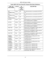
... no backup power is supplied. POWER FEEDING Green On The BPS-120 is providing power to the connected device. POWER FEEDING Amber Off The BPS-120 is providing power to the connected device. POWER FEEDING Red On The BPS-120 is in standby mode. STANDBY Green Off The BPS-120 is providing power to ... On Output port is unavailable to OUTPUT1-6 but no backup power is in standby mode. STANDBY Amber On The BPS-120 is supplied. ACTIVE Amber Off External device is connected to supply external power because another is in use . INACTIVE Green On Output...
... no backup power is supplied. POWER FEEDING Green On The BPS-120 is providing power to the connected device. POWER FEEDING Amber Off The BPS-120 is providing power to the connected device. POWER FEEDING Red On The BPS-120 is in standby mode. STANDBY Green Off The BPS-120 is providing power to ... On Output port is unavailable to OUTPUT1-6 but no backup power is in standby mode. STANDBY Amber On The BPS-120 is supplied. ACTIVE Amber Off External device is connected to supply external power because another is in use . INACTIVE Green On Output...
