User Guide
Page 3
... Over Ethernet (PoE) ...7 Chapter 2 Hardware Description and Connection 9 2.1 Rear Panel ...9 2.1.1 Rear Panel Power Connection 9 2.2 Front Panel ...9 2.2.1 RJ-45 Auto-negotiating Ports 10 2.2.2 IEEE 802.3az EEE ...10 2.2.3 SFP Slots (GS1100-24 Only 10 2.2.4 Front Panel Connections ...12 2.2.5 Front Panel LEDs ...12 2.3 Hardware Installation ...14 2.3.1 Wall Mounting ...14 2.3.2 Rack Mounting ...15 2.3.3 Mounting the Switch on a Rack 16 Chapter 3 Troubleshooting...19 3.1 Improper Network Cabling and Topology 20 Appendix A Legal Information...21 Index ...23 GS1100 Series User's Guide 3
... Over Ethernet (PoE) ...7 Chapter 2 Hardware Description and Connection 9 2.1 Rear Panel ...9 2.1.1 Rear Panel Power Connection 9 2.2 Front Panel ...9 2.2.1 RJ-45 Auto-negotiating Ports 10 2.2.2 IEEE 802.3az EEE ...10 2.2.3 SFP Slots (GS1100-24 Only 10 2.2.4 Front Panel Connections ...12 2.2.5 Front Panel LEDs ...12 2.3 Hardware Installation ...14 2.3.1 Wall Mounting ...14 2.3.2 Rack Mounting ...15 2.3.3 Mounting the Switch on a Rack 16 Chapter 3 Troubleshooting...19 3.1 Improper Network Cabling and Topology 20 Appendix A Legal Information...21 Index ...23 GS1100 Series User's Guide 3
User Guide
Page 5
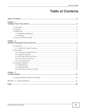
... connections to the connected PoE powered devices. It can be used to received packets. Use SFP transceivers in compliance with IEEE 802.3az Energy Efficient Ethernet (EEE). The Switch has a built-in algorithm that can operate in low power idle mode in these slots for high-speed networking. This User's Guide covers the following models: GS1100-8HP, GS1100-16, GS1100-24, and GS110024E. The Switch is a 10/100/1000 Mbps multi-port switch...
... connections to the connected PoE powered devices. It can be used to received packets. Use SFP transceivers in compliance with IEEE 802.3az Energy Efficient Ethernet (EEE). The Switch has a built-in algorithm that can operate in low power idle mode in these slots for high-speed networking. This User's Guide covers the following models: GS1100-8HP, GS1100-16, GS1100-24, and GS110024E. The Switch is a 10/100/1000 Mbps multi-port switch...
User Guide
Page 6
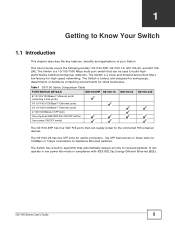
...-forward switching. • Supports automatic address learning. • Supports IEEE 802.3az EEE • Supports IEEE 802.3af and IEEE 802.3at PoE standards (only GS1100-8HP) • Full wire speed forwarding rate. • Supports 802.1p CoS. • Embedded 8K MAC address table providing 8000 MAC addresses entries. 1.3 Applications This section provides two network topology examples in which the Switch is used. 6 GS1100 Series User's Guide Chapter 1 Getting to Know Your Switch Figure 1 Front Panel GS1100...
...-forward switching. • Supports automatic address learning. • Supports IEEE 802.3az EEE • Supports IEEE 802.3af and IEEE 802.3at PoE standards (only GS1100-8HP) • Full wire speed forwarding rate. • Supports 802.1p CoS. • Embedded 8K MAC address table providing 8000 MAC addresses entries. 1.3 Applications This section provides two network topology examples in which the Switch is used. 6 GS1100 Series User's Guide Chapter 1 Getting to Know Your Switch Figure 1 Front Panel GS1100...

User Guide
Page 7
... traffic users. Figure 3 Bridging Example 1.4 Power Over Ethernet (PoE) The PoE function is an ideal solution for a group of the Switch in the near future. The two networks (RD and Sales), the standalone server and the computers can be expected in an enterprise environment. Figure 2 Standalone Workgroup Example 1.3.2 Bridging With its large address table and high performance, the Switch is available for connecting network segments. The Switch...
... traffic users. Figure 3 Bridging Example 1.4 Power Over Ethernet (PoE) The PoE function is an ideal solution for a group of the Switch in the near future. The two networks (RD and Sales), the standalone server and the computers can be expected in an enterprise environment. Figure 2 Standalone Workgroup Example 1.3.2 Bridging With its large address table and high performance, the Switch is available for connecting network segments. The Switch...

User Guide
Page 8
... get their power directly from another device through a 10/100/1000 Mbps Ethernet port. Figure 4 Powered Device Examples 8 GS1100 Series User's Guide Aside from minimizing the need for cables and wires, PoE removes the hassle of up devices. Chapter 1 Getting to Know Your Switch Ports 1 to 4 on the GS1100-8HP are IEEE 802.3at High Power over Ethernet) so that supports PoE (Power over Ethernet (PoE) compliant and can receive power from the...
... get their power directly from another device through a 10/100/1000 Mbps Ethernet port. Figure 4 Powered Device Examples 8 GS1100 Series User's Guide Aside from minimizing the need for cables and wires, PoE removes the hassle of up devices. Chapter 1 Getting to Know Your Switch Ports 1 to 4 on the GS1100-8HP are IEEE 802.3at High Power over Ethernet) so that supports PoE (Power over Ethernet (PoE) compliant and can receive power from the...
User Guide
Page 9
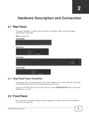
... the Switch includes the auto-negotiating 10 Base-T/100 Base-TX/1000 Base-T RJ-45 ports and the LEDs. CHAPTER 2 Hardware Description and Connection 2.1 Rear Panel The power receptacle is located on the back of the Switch and the other end to the appropriate power source. GS1100 Series User's Guide 9 Figure 5 Rear Panel GS1100-8HP GS1100-16 GS1100-24 GS1100-24E 2.1.1 Rear Panel Power Connection Connect one end of the supplied power...
... the Switch includes the auto-negotiating 10 Base-T/100 Base-TX/1000 Base-T RJ-45 ports and the LEDs. CHAPTER 2 Hardware Description and Connection 2.1 Rear Panel The power receptacle is located on the back of the Switch and the other end to the appropriate power source. GS1100 Series User's Guide 9 Figure 5 Rear Panel GS1100-8HP GS1100-16 GS1100-24 GS1100-24E 2.1.1 Rear Panel Power Connection Connect one end of the supplied power...
User Guide
Page 10
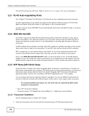
... into an operating fiber-optic module's connectors. • Type: SFP connection interface • Connection speed: 100 Megabit per second (Mbps) or 1 Gigabit per -system basis in the Switch to install a SFP module. 1 Insert the transceiver into power saving mode and switch off part of receive and transmit circuitry when it . 2.2.3 SFP Slots (GS1100-24 Only) These are auto-negotiating and auto-crossover. An auto-negotiating port can change transceivers while the Switch is configured on the EEE...
... into an operating fiber-optic module's connectors. • Type: SFP connection interface • Connection speed: 100 Megabit per second (Mbps) or 1 Gigabit per -system basis in the Switch to install a SFP module. 1 Insert the transceiver into power saving mode and switch off part of receive and transmit circuitry when it . 2.2.3 SFP Slots (GS1100-24 Only) These are auto-negotiating and auto-crossover. An auto-negotiating port can change transceivers while the Switch is configured on the EEE...
User Guide
Page 11
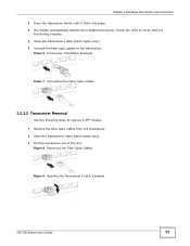
...). 5 Connect the fiber optic cables to remove a SFP module. 1 Remove the fiber optic cables from the transceiver. 2 Open the transceiver's latch (latch styles vary). 3 Pull the transceiver out of the slot. Figure 8 Removing the Fiber Optic Cables Figure 9 Opening the Transceiver's Latch Example GS1100 Series User's Guide 11 Check the LEDs to verify that it clicks into place. 3 The Switch automatically detects the installed transceiver. Figure 6 Transceiver Installation Example Figure 7 Connecting the Fiber Optic Cables 2.2.3.2 Transceiver Removal Use...
...). 5 Connect the fiber optic cables to remove a SFP module. 1 Remove the fiber optic cables from the transceiver. 2 Open the transceiver's latch (latch styles vary). 3 Pull the transceiver out of the slot. Figure 8 Removing the Fiber Optic Cables Figure 9 Opening the Transceiver's Latch Example GS1100 Series User's Guide 11 Check the LEDs to verify that it clicks into place. 3 The Switch automatically detects the installed transceiver. Figure 6 Transceiver Installation Example Figure 7 Connecting the Fiber Optic Cables 2.2.3.2 Transceiver Removal Use...
User Guide
Page 12
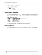
... ports. 2.2.5 Front Panel LEDs The LED Indicators give real-time information about the status of the LEDs. 12 GS1100 Series User's Guide Table 2 Network Cable Types SPEED NETWORK CABLE TYPE 10 Mbps Category 3, 4 or 5 UTP/STP 100 Mbps Category 5 UTP/STP 1000 Mbps Category 5e, 6 UTP/STP You can use either crossover or straight-through cables for the different connection speeds. . The following table provides descriptions of the Switch. Chapter 2 Hardware Description and Connection Figure 10 Transceiver Removal Example 2.2.4 Front Panel Connections...
... ports. 2.2.5 Front Panel LEDs The LED Indicators give real-time information about the status of the LEDs. 12 GS1100 Series User's Guide Table 2 Network Cable Types SPEED NETWORK CABLE TYPE 10 Mbps Category 3, 4 or 5 UTP/STP 100 Mbps Category 5 UTP/STP 1000 Mbps Category 5e, 6 UTP/STP You can use either crossover or straight-through cables for the different connection speeds. . The following table provides descriptions of the Switch. Chapter 2 Hardware Description and Connection Figure 10 Transceiver Removal Example 2.2.4 Front Panel Connections...
User Guide
Page 13
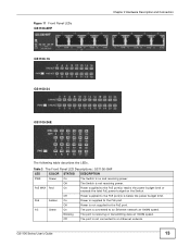
... On Power supplied to an Ethernet network at 1000M speed. Off The Switch is below the power budget limit. Figure 11 Front Panel LEDs GS1100-8HP GS1100-16 GS1100-24 GS1100-24E Chapter 2 Hardware Description and Connection The following table describes the LEDs. PoE Amber On Power is not connected to the PoE port. Blinking The port is on the Switch. Off The port is supplied to an Ethernet network. GS1100 Series User's Guide 13 Table 3 The Front Panel LED Descriptions: GS1100-8HP LED COLOR STATUS DESCRIPTION PWR Green...
... On Power supplied to an Ethernet network at 1000M speed. Off The Switch is below the power budget limit. Figure 11 Front Panel LEDs GS1100-8HP GS1100-16 GS1100-24 GS1100-24E Chapter 2 Hardware Description and Connection The following table describes the LEDs. PoE Amber On Power is not connected to the PoE port. Blinking The port is on the Switch. Off The port is supplied to an Ethernet network. GS1100 Series User's Guide 13 Table 3 The Front Panel LED Descriptions: GS1100-8HP LED COLOR STATUS DESCRIPTION PWR Green...

User Guide
Page 14
... power cables and turn on top of your Switch to a wall. 14 GS1100 Series User's Guide For GS1100-16, GS1100-24 and GS110-24E, the size is on page 15 for ventilation. • The Switch should have it for instruction. Chapter 2 Hardware Description and Connection Table 3 The Front Panel LED Descriptions: GS1100-8HP LED COLOR STATUS DESCRIPTION 10/100 Amber On The port is able to support the weight of the Switch. LINK/ ACT Green On Blinking...
... power cables and turn on top of your Switch to a wall. 14 GS1100 Series User's Guide For GS1100-16, GS1100-24 and GS110-24E, the size is on page 15 for ventilation. • The Switch should have it for instruction. Chapter 2 Hardware Description and Connection Table 3 The Front Panel LED Descriptions: GS1100-8HP LED COLOR STATUS DESCRIPTION 10/100 Amber On The port is able to support the weight of the Switch. LINK/ ACT Green On Blinking...

User Guide
Page 15
Rack-mounted Installation Requirements • Two mounting brackets. GS1100 Series User's Guide 15 Do not screw the screws all the way in to mount your Switch into the screw slots and the connection cables to place the screws. leave a small gap between the centers of the Switch with 6 mm ~ 8 mm (0.24" ~ 0.31") wide heads. Note: Make sure the screws are securely fixed to the...
Rack-mounted Installation Requirements • Two mounting brackets. GS1100 Series User's Guide 15 Do not screw the screws all the way in to mount your Switch into the screw slots and the connection cables to place the screws. leave a small gap between the centers of the Switch with 6 mm ~ 8 mm (0.24" ~ 0.31") wide heads. Note: Make sure the screws are securely fixed to the...

User Guide
Page 16
... the rack, lining up the four screw holes on the bracket with the screw holes on the side of all necessary precautions to install the second mounting bracket on the side of the Switch. 4 You may damage the unit. Precautions • Make sure the rack will safely support the combined weight of the rack. 16 GS1100 Series User's Guide Chapter 2 Hardware Description and Connection...
... the rack, lining up the four screw holes on the bracket with the screw holes on the side of all necessary precautions to install the second mounting bracket on the side of the Switch. 4 You may damage the unit. Precautions • Make sure the rack will safely support the combined weight of the rack. 16 GS1100 Series User's Guide Chapter 2 Hardware Description and Connection...
User Guide
Page 17
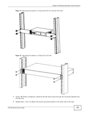
GS1100 Series User's Guide 17 Chapter 2 Hardware Description and Connection Figure 14 Mounting the Switch on a Rack (GS1100-16 and GS1100-24E) Figure 15 Mounting the Switch on a Rack (GS1100-24) 2 Using a #2 Philips screwdriver, install the M5 flat head screws through the mounting bracket holes into the rack. 3 Repeat steps 1 and 2 to attach the second mounting bracket on the other side of the rack.
GS1100 Series User's Guide 17 Chapter 2 Hardware Description and Connection Figure 14 Mounting the Switch on a Rack (GS1100-16 and GS1100-24E) Figure 15 Mounting the Switch on a Rack (GS1100-24) 2 Using a #2 Philips screwdriver, install the M5 flat head screws through the mounting bracket holes into the rack. 3 Repeat steps 1 and 2 to attach the second mounting bracket on the other side of the rack.

User Guide
Page 19
... power source. GS1100 Series User's Guide 19 The PoE LED is off and/or power is not being supplied to my PoE-enabled device. (For GS1100-8HP) • Check to see Section 3.1 on and that the attached device(s) is used and its length does not exceed 100 meters. Troubleshoot the Switch using the LEDs to detect problems. The PWR LED on the front panel does not light up when a device is connected...
... power source. GS1100 Series User's Guide 19 The PoE LED is off and/or power is not being supplied to my PoE-enabled device. (For GS1100-8HP) • Check to see Section 3.1 on and that the attached device(s) is used and its length does not exceed 100 meters. Troubleshoot the Switch using the LEDs to detect problems. The PWR LED on the front panel does not light up when a device is connected...

User Guide
Page 20
... network topology. 20 GS1100 Series User's Guide Chapter 3 Troubleshooting 3.1 Improper Network Cabling and Topology Improper network cabling or topology setup is more information on your network performance. Too many hubs between the connected computers in the data path The network cables should not be affected. Make sure there are needed, transmission quality may affect data rates and have an impact on network cable types. Figure 16 Troubleshooting Improper Network Cabling and Topology PROBLEM Faulty cables Non-standard network cables Cabling...
... network topology. 20 GS1100 Series User's Guide Chapter 3 Troubleshooting 3.1 Improper Network Cabling and Topology Improper network cabling or topology setup is more information on your network performance. Too many hubs between the connected computers in the data path The network cables should not be affected. Make sure there are needed, transmission quality may affect data rates and have an impact on network cable types. Figure 16 Troubleshooting Improper Network Cabling and Topology PROBLEM Faulty cables Non-standard network cables Cabling...
User Guide
Page 21
... may cause harmful interference to view this product. PRODUIT CONFORME SELON 21 CFR 1040.10 ET 1040.11. This warranty shall not apply if the product has been modified, misused, tampered with Part 15 of God, or subjected to proper operating condition. GS1100 Series User's Guide 21 ZyXEL further reserves the right to change without notice. Certifications Federal...
... may cause harmful interference to view this product. PRODUIT CONFORME SELON 21 CFR 1040.10 ET 1040.11. This warranty shall not apply if the product has been modified, misused, tampered with Part 15 of God, or subjected to proper operating condition. GS1100 Series User's Guide 21 ZyXEL further reserves the right to change without notice. Certifications Federal...
User Guide
Page 22
... you to receive e-mail notices of firmware upgrades and information at www.zyxel.com for global products, or at http://www.zyxel.com/web/support_warranty_info.php. Replace a fuse only with this product near water, for example, in Europe). • Use ONLY power wires of the correct voltage. • Do NOT allow anything to the right supply voltage (for your local vendor to...
... you to receive e-mail notices of firmware upgrades and information at www.zyxel.com for global products, or at http://www.zyxel.com/web/support_warranty_info.php. Replace a fuse only with this product near water, for example, in Europe). • Use ONLY power wires of the correct voltage. • Do NOT allow anything to the right supply voltage (for your local vendor to...

User Guide
Page 23
Numbers 10/100/1000 Mbps 5 A Applications 6 Segment Bridge 7 auto-negotiating ports 10 C Cabling Length 20 certifications notices 21 viewing 21 copyright 21 D Data path loop 20 disclaimer 21 E EEE 5, 10 Energy Efficient Ethernet 10 F Faulty cables 20 FCC interference statement 21 Front Panel 9 GS1100 Series User's Guide Index Index Front Panel Connections 12 H High Power over Ethernet 8 I IEEE 802.3at 8 IEEE 802.3az 10 installation precautions 16...
Numbers 10/100/1000 Mbps 5 A Applications 6 Segment Bridge 7 auto-negotiating ports 10 C Cabling Length 20 certifications notices 21 viewing 21 copyright 21 D Data path loop 20 disclaimer 21 E EEE 5, 10 Energy Efficient Ethernet 10 F Faulty cables 20 FCC interference statement 21 Front Panel 9 GS1100 Series User's Guide Index Index Front Panel Connections 12 H High Power over Ethernet 8 I IEEE 802.3at 8 IEEE 802.3az 10 installation precautions 16...
User Guide
Page 24
Index P PD 8 PoE 8 power supplying 8 Power over Ethernet 8 power saving 10 powered device 8 product registration 22 R rack mounting 15 Rear Panel 9 Rear Panel Power Connection 9 registration product 22 S safety warnings 22 Small Form-factor Pluggable (SFP) 10 Standalone Workgroup 7 T transceiver MultiSource Agreement (MSA) 10 transceivers 10 installation 10 removal 11 Troubleshooting Improper Network Cabling and Topology 20 W wall mounting 14 warranty 21 note 22 24 GS1100 Series User's Guide
Index P PD 8 PoE 8 power supplying 8 Power over Ethernet 8 power saving 10 powered device 8 product registration 22 R rack mounting 15 Rear Panel 9 Rear Panel Power Connection 9 registration product 22 S safety warnings 22 Small Form-factor Pluggable (SFP) 10 Standalone Workgroup 7 T transceiver MultiSource Agreement (MSA) 10 transceivers 10 installation 10 removal 11 Troubleshooting Improper Network Cabling and Topology 20 W wall mounting 14 warranty 21 note 22 24 GS1100 Series User's Guide


