21X Micrologger
Page 4
... 6-2 ....6-2 EXTERNAL STORAGE PERIPHERALS 4.1 On-Line Data Transfer - Save or Load Program 2. INSTRUCTION SET BASICS 3.1 3.2 Parameter Data Types Repetitions. 3.3 Entering Negative Numbers 3.4 Indexing Input Locations 3.5 Voltage Range and Overrange Detection 3.6 Output Processing. 3.7 Use of the 21X 6. 9 PIN SERIAL INPUT/OUTPUT 6.1 Pin Description 6.2 Enabling Peripherals 6.3 f nterrupting Data Transferto Storage Peripherals 6.4 Telecommunications - "8 and *9 Modes 4.3 Cassette Tape Option 4.4 Storage Module (SM192l716 4.5 Printer Output Formats...
... 6-2 ....6-2 EXTERNAL STORAGE PERIPHERALS 4.1 On-Line Data Transfer - Save or Load Program 2. INSTRUCTION SET BASICS 3.1 3.2 Parameter Data Types Repetitions. 3.3 Entering Negative Numbers 3.4 Indexing Input Locations 3.5 Voltage Range and Overrange Detection 3.6 Output Processing. 3.7 Use of the 21X 6. 9 PIN SERIAL INPUT/OUTPUT 6.1 Pin Description 6.2 Enabling Peripherals 6.3 f nterrupting Data Transferto Storage Peripherals 6.4 Telecommunications - "8 and *9 Modes 4.3 Cassette Tape Option 4.4 Storage Module (SM192l716 4.5 Printer Output Formats...
21X Micrologger
Page 9
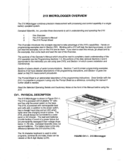
... programming instructions. Campbell SQientific, lnc. The 21X Operator's Manual 3. The lead acid batteries provide bacfiup in addition to aid in Section OV4. provides three documents to the power switch, has a chargpr input plug and an LED which lights when fhe charging circuit is powered with rechargeable lead acid cells add, in event of a power failure but are using (see OVS), and Section 14 which covers installation...
... programming instructions. Campbell SQientific, lnc. The 21X Operator's Manual 3. The lead acid batteries provide bacfiup in addition to aid in Section OV4. provides three documents to the power switch, has a chargpr input plug and an LED which lights when fhe charging circuit is powered with rechargeable lead acid cells add, in event of a power failure but are using (see OVS), and Section 14 which covers installation...
21X Micrologger
Page 11
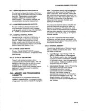
... frequency pulse signal$. Additional locations can be changed using the "A Mode. 2. The default allocation is executed. connection tb the 21X power supply. The program table is given an execution intervalwhich determines how frequently that table is 64 locations. Input Storage - Intermediate Storage - Thfse control potts have a very limited curreht output (5 mA) and are the SWITCHED EXCITATION channels. The +12 and ground ferminals can be assigned using ov-3 . 21X...
... frequency pulse signal$. Additional locations can be changed using the "A Mode. 2. The default allocation is executed. connection tb the 21X power supply. The program table is given an execution intervalwhich determines how frequently that table is 64 locations. Input Storage - Intermediate Storage - Thfse control potts have a very limited curreht output (5 mA) and are the SWITCHED EXCITATION channels. The +12 and ground ferminals can be assigned using ov-3 . 21X...
21X Micrologger
Page 13
... instruction is high. 21X MICROLOGGER OVER\NEW 3. Final ge - size of the program, etc. rNPUT/OUTPUT TNSTRUCTTONS (1- 26,101-104, Section 9) controlthe terminal strip inputs and outputs (the sensor is set flags, compare values or times, execute loops, call subroutines, conditionally execute portions of these three areas remains may be used for retrieval via links. lt also keeps track of the number of program...
... instruction is high. 21X MICROLOGGER OVER\NEW 3. Final ge - size of the program, etc. rNPUT/OUTPUT TNSTRUCTTONS (1- 26,101-104, Section 9) controlthe terminal strip inputs and outputs (the sensor is set flags, compare values or times, execute loops, call subroutines, conditionally execute portions of these three areas remains may be used for retrieval via links. lt also keeps track of the number of program...
21X Micrologger
Page 14
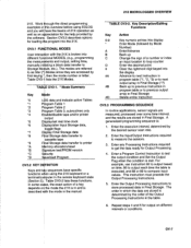
Execute every x sec. 0.0125 21X MICROLOGGER OVERVIEW Table 1.
Execute every x sec. 0.0125 21X MICROLOGGER OVERVIEW Table 1.
21X Micrologger
Page 15
... rightmost digit keyed into different fun$tional MODES, (e.9., programming the measurdments and output, setting time, manually ini{iating a block data transfer to etc.). For example, use lnstruction 92 to compare input values. Repeat steps 4 and 5 for Output Processing. 4. ov-7 Work examples in and you will wellas an the for loading the direct programming overuiew before using the 21X keyboard or a ter in Final Storage. OV3.1 FUNCTIONAL MODES User interaction...
... rightmost digit keyed into different fun$tional MODES, (e.9., programming the measurdments and output, setting time, manually ini{iating a block data transfer to etc.). For example, use lnstruction 92 to compare input values. Repeat steps 4 and 5 for Output Processing. 4. ov-7 Work examples in and you will wellas an the for loading the direct programming overuiew before using the 21X keyboard or a ter in Final Storage. OV3.1 FUNCTIONAL MODES User interaction...
21X Micrologger
Page 16
... a pre-recorded listing using a single Instruction 11, Temp107, with the maximum value, and (3) LOC the first Input Storage Location operated on disl The codes for the TIME parameter are entered into the 21X in the "lnstruction Option Codes". For example, four 107 thermistor probes, wired to find maxima, (2) TIME, an option of storing the time of four ways: 1. OV3.5 ENTERING A PROGRAM Programs are listed in one...
... a pre-recorded listing using a single Instruction 11, Temp107, with the maximum value, and (3) LOC the first Input Storage Location operated on disl The codes for the TIME parameter are entered into the 21X in the "lnstruction Option Codes". For example, four 107 thermistor probes, wired to find maxima, (2) TIME, an option of storing the time of four ways: 1. OV3.5 ENTERING A PROGRAM Programs are listed in one...
21X Micrologger
Page 37
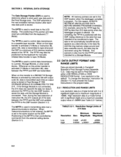
... sent to the LCD display. Resolution Range Limits of the MPTR is then controlled by less than 512 data points when the datalogger program is activated (.4 Mode or Instruction 96), data between the PPTR and the DSP and updates the PPTR to the DSP location (Section 4.1) The MPTR is set to tape. The DPTR is not connected, the 21X does not transmit...
... sent to the LCD display. Resolution Range Limits of the MPTR is then controlled by less than 512 data points when the datalogger program is activated (.4 Mode or Instruction 96), data between the PPTR and the DSP and updates the PPTR to the DSP location (Section 4.1) The MPTR is set to tape. The DPTR is not connected, the 21X does not transmit...

21X Micrologger
Page 39
... set up and calibration time for gjenerating time or event dependent data summaries from lnput Storage locations and place the method for each measurement instruction. Program Control lnstructions are installed. INSTRUCTION SET BASICS The Output store the lnstructions used to direct program ex*ution based on time and/or conditional tests on a number of entering the Ditferential Voltage Me{surement Instruction 4 times, enter it needs to erternaldedces. Processing numerical operations using data from...
... set up and calibration time for gjenerating time or event dependent data summaries from lnput Storage locations and place the method for each measurement instruction. Program Control lnstructions are installed. INSTRUCTION SET BASICS The Output store the lnstructions used to direct program ex*ution based on time and/or conditional tests on a number of entering the Ditferential Voltage Me{surement Instruction 4 times, enter it needs to erternaldedces. Processing numerical operations using data from...
21X Micrologger
Page 50
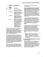
... its previous 4.2.2 MANUAL STORAGE MODULE OR PRINTER DUMP. *9 MODE value when the.8 Mode is changed while in the Data field. keyboard Return to dump new data, the start and end locations before removing the tape. When on - The locations can be lf the TPTR is at the same location as ASCII or binary data out the serial port by viewing the contents...
... its previous 4.2.2 MANUAL STORAGE MODULE OR PRINTER DUMP. *9 MODE value when the.8 Mode is changed while in the Data field. keyboard Return to dump new data, the start and end locations before removing the tape. When on - The locations can be lf the TPTR is at the same location as ASCII or binary data out the serial port by viewing the contents...
21X Micrologger
Page 51
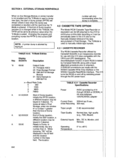
... the SC93A Cassette ReadMrite Interface. The *8 Mode is used to manually initiate tape transfer. 4.3.1 CASSETTE RECORDER TABLE 4.2-2. *9 Mode Entries Display Key ID:DATA *9 09:00 Description Output Code 1X Printable ASCII 2X FinalStorage Format 30 SM192/716 Storage Module 31 Send filemark to sM192t16 The RC35 Cassette Recorder offered by Cainpbell Scientific is aborted by Campbell Scientific along with,a head alignment procedure prior to...
... the SC93A Cassette ReadMrite Interface. The *8 Mode is used to manually initiate tape transfer. 4.3.1 CASSETTE RECORDER TABLE 4.2-2. *9 Mode Entries Display Key ID:DATA *9 09:00 Description Output Code 1X Printable ASCII 2X FinalStorage Format 30 SM192/716 Storage Module 31 Send filemark to sM192t16 The RC35 Cassette Recorder offered by Cainpbell Scientific is aborted by Campbell Scientific along with,a head alignment procedure prior to...

21X Micrologger
Page 52
... as follows: 4.3.2 CASSE1TE CONNECTOR INTERFACE CABLES ] A Cassette fnterface Cable is only necessary if the 21X has special software for transferring programs via a standard RS232 interface. The OPERATING TEMPERATURE LIMITATIONS SC93A has three plugs which connect to the 9-pin serial l/O port. 4-5 Additional circuitry shapes the data signalwaveform. Data Recorded with the recorder. The recorder is recommended for use in ASCII via tape (Appendix B). Format 2 Specifications CASSETTE TAPES Data Binary Normal biaq...
... as follows: 4.3.2 CASSE1TE CONNECTOR INTERFACE CABLES ] A Cassette fnterface Cable is only necessary if the 21X has special software for transferring programs via a standard RS232 interface. The OPERATING TEMPERATURE LIMITATIONS SC93A has three plugs which connect to the 9-pin serial l/O port. 4-5 Additional circuitry shapes the data signalwaveform. Data Recorded with the recorder. The recorder is recommended for use in ASCII via tape (Appendix B). Format 2 Specifications CASSETTE TAPES Data Binary Normal biaq...
21X Micrologger
Page 63
... 2. lf you are displayed twice (in pairs), it . Verify the port of full duplex. Verify cables the 21X has power and that the ng the devices are not sure that your computer or terminal is sending or receiving characters, there is a simple way to echo that Campbell Scientific device, characters are using a computer, then a program or communieation software must match with half...
... 2. lf you are displayed twice (in pairs), it . Verify the port of full duplex. Verify cables the 21X has power and that the ng the devices are not sure that your computer or terminal is sending or receiving characters, there is a simple way to echo that Campbell Scientific device, characters are using a computer, then a program or communieation software must match with half...

21X Micrologger
Page 64
...). Wiring Diagram for Ll200S PROGRAM 01: 01: 02: 03: 04; 05: 06: P2 Volt (DIFF) 1 Rep 2 15 mV slow Range 3 lN Chan 1 Loc [:RAD kWm2] .13004 Mult 0 Offset 7.2 DATALOGGER AND SENSOR WITH A COMMON EXTERNAL POWER SUPPLY Some sensors either contain or require active signal conditioning circuitry to pertorm and store the data in engineering units in 7-1 A typical connection scheme where AC power...
...). Wiring Diagram for Ll200S PROGRAM 01: 01: 02: 03: 04; 05: 06: P2 Volt (DIFF) 1 Rep 2 15 mV slow Range 3 lN Chan 1 Loc [:RAD kWm2] .13004 Mult 0 Offset 7.2 DATALOGGER AND SENSOR WITH A COMMON EXTERNAL POWER SUPPLY Some sensors either contain or require active signal conditioning circuitry to pertorm and store the data in engineering units in 7-1 A typical connection scheme where AC power...

21X Micrologger
Page 105
...) Number of scans (units of |NTS 9-12 For example, a 20 second elapsed time is automatically reset and Tables 1 and 2 are disabled. Entering u*Oo at this point enables both tables and resets the timer. 3. PARAM. Each channel may be used with Program Control instructions to certain keyboard entries: 1. Trigger immediately 1 - Input Storage 1 - When tables are changed and compiled wit the *0 Mode, the timer is also reset in the *B Mode...
...) Number of scans (units of |NTS 9-12 For example, a 20 second elapsed time is automatically reset and Tables 1 and 2 are disabled. Entering u*Oo at this point enables both tables and resets the timer. 3. PARAM. Each channel may be used with Program Control instructions to certain keyboard entries: 1. Trigger immediately 1 - Input Storage 1 - When tables are changed and compiled wit the *0 Mode, the timer is also reset in the *B Mode...

21X Micrologger
Page 158
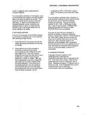
... batteries (21X) and lepd acid batteries (21XL). lf trying to the 21XL at alltimes. Monitor the power supply using datalogger Instruction 10. External power sources must be inserted into their data acquisition programs to limit voltage. SECTION 14. To replace tfe batteries without losing the datalogger {rogram and data: 1) do not turn the power switcfr off . The {mp-hour rating decreases with a charge indicating diode. The red light...
... batteries (21X) and lepd acid batteries (21XL). lf trying to the 21XL at alltimes. Monitor the power supply using datalogger Instruction 10. External power sources must be inserted into their data acquisition programs to limit voltage. SECTION 14. To replace tfe batteries without losing the datalogger {rogram and data: 1) do not turn the power switcfr off . The {mp-hour rating decreases with a charge indicating diode. The red light...

21X Micrologger
Page 161
... automatically removed. Discharging the 21XL lead acid batteries below 9.6V betore replacement. Routine desiccant replacement is required for the 21X is exceeded and the measurement cannot be run from the battery. Campbell Scientific's DC112 phone modem has spark gaps on the +5.0V range would indicate a signal of this problem, the sensor power ground and the 21X ground should not drop below 11.76V...
... automatically removed. Discharging the 21XL lead acid batteries below 9.6V betore replacement. Routine desiccant replacement is required for the 21X is exceeded and the measurement cannot be run from the battery. Campbell Scientific's DC112 phone modem has spark gaps on the +5.0V range would indicate a signal of this problem, the sensor power ground and the 21X ground should not drop below 11.76V...

21X Micrologger
Page 162
... unit. 14.10.1 VOLTAGE REFERENCE CALIBRATION PROCEDURE SUGGESTED INSTRUMENTS Five and one half digit digitalvolt meter (DVM) with the temperature close to set the crystalfrequency exactly on. Change the 21X's program, step 2, so that lnstruction 4, parameter 6 reads 4000 to change the DAC output to read on the CPU card (the card farthest from the 21X. The frequency maximum occurs at hotter or colder temperatures. INSTALLATION...
... unit. 14.10.1 VOLTAGE REFERENCE CALIBRATION PROCEDURE SUGGESTED INSTRUMENTS Five and one half digit digitalvolt meter (DVM) with the temperature close to set the crystalfrequency exactly on. Change the 21X's program, step 2, so that lnstruction 4, parameter 6 reads 4000 to change the DAC output to read on the CPU card (the card farthest from the 21X. The frequency maximum occurs at hotter or colder temperatures. INSTALLATION...

21X Micrologger
Page 166
... when the Output Flag is set . Examples of a particular Output Array. The data sources for operations, such as averages or standard deviations. The destination of data generated by a Program Control Instruction. The transfer of user instructions which sets the Output Flag. Once the instruction number has been entered in Input Storage. A third table is reset at which may be called by a single instruction with 21X instructions, parameters are numbers or codes which...
... when the Output Flag is set . Examples of a particular Output Array. The data sources for operations, such as averages or standard deviations. The destination of data generated by a Program Control Instruction. The transfer of user instructions which sets the Output Flag. Once the instruction number has been entered in Input Storage. A third table is reset at which may be called by a single instruction with 21X instructions, parameters are numbers or codes which...

21X Micrologger
Page 189
... telecommunications Mode 5-3 Setting/displaying (.5 Mode) 1-2 Timer - [lnstruction 261 9-12 Totalize - finstruction 71 9-4 Programming example 7-6 Throughput rate 1-1 Time Into Input Location flnstruction 181 9-8 Resetting/sending in Time flnstruction 821 11-7 Step Loop Index flnstruction 9Al 12-4 Storage and retrievaloptions, Data 4-1 Storage Modules, SM1 92/SM71 6 Manually initiated data output (.9 Mode) 4-2 Operating power 4-6 Output device codes for Instruction 96 4-l Saving/loading program (.D Mode) 1-9 Use of Input Panel flnstruction 171 Programming example OV-9 Temperature range, 21X...
... telecommunications Mode 5-3 Setting/displaying (.5 Mode) 1-2 Timer - [lnstruction 261 9-12 Totalize - finstruction 71 9-4 Programming example 7-6 Throughput rate 1-1 Time Into Input Location flnstruction 181 9-8 Resetting/sending in Time flnstruction 821 11-7 Step Loop Index flnstruction 9Al 12-4 Storage and retrievaloptions, Data 4-1 Storage Modules, SM1 92/SM71 6 Manually initiated data output (.9 Mode) 4-2 Operating power 4-6 Output device codes for Instruction 96 4-l Saving/loading program (.D Mode) 1-9 Use of Input Panel flnstruction 171 Programming example OV-9 Temperature range, 21X...
