
CR5000 Measurement and Control Module
Page 16
CR5000 Overview OV4.1 Data Display Data Run/Stop Program File Status Configure, Settings Cursor to Data and Press Enter Real Time Tables Real Time Custom Final Storage Data Reset Data Table Graph Setup OV-12 List of Data Tables created by active program List of Data Tables created by active program List of Data Tables created by active program All Tables List of Data Tables created by active program Graph Type: Scope Scaler: Manual Upper: 0.000000 Lower: 0.000000 Display Val Off Display Max Off Display Min Off
CR5000 Overview OV4.1 Data Display Data Run/Stop Program File Status Configure, Settings Cursor to Data and Press Enter Real Time Tables Real Time Custom Final Storage Data Reset Data Table Graph Setup OV-12 List of Data Tables created by active program List of Data Tables created by active program List of Data Tables created by active program All Tables List of Data Tables created by active program Graph Type: Scope Scaler: Manual Upper: 0.000000 Lower: 0.000000 Display Val Off Display Max Off Display Min Off

CR5000 Measurement and Control Module
Page 17
...Enter to desired Table and press Enter Tref TCTemp(1) TCTemp(2) TCTemp(3) Flag(1) Flag(2) Flag(3) Flag(4) Press Graph/ Char for Graph Setup Scaler Manual Upper: 30.000000 Lower: 20.000000 Display Val On Display Max On Display Min On Graph Type Roll New values are displayed as they are... : -1.0000 : 0.00000 : 0.00000 : 0.00000 22.35 Press Ins for Graph of Data Tables created by active program. OV-13 For Example, Table1 Temps Public CR5000 Overview Cursor to edit value. OV4.1.1 Real Time Tables List of selected field 30.0 20.00 : 23.0234 : 19.6243 : 19.3429 : 21.2003 : -1.0000...
...Enter to desired Table and press Enter Tref TCTemp(1) TCTemp(2) TCTemp(3) Flag(1) Flag(2) Flag(3) Flag(4) Press Graph/ Char for Graph Setup Scaler Manual Upper: 30.000000 Lower: 20.000000 Display Val On Display Max On Display Min On Graph Type Roll New values are displayed as they are... : -1.0000 : 0.00000 : 0.00000 : 0.00000 22.35 Press Ins for Graph of Data Tables created by active program. OV-13 For Example, Table1 Temps Public CR5000 Overview Cursor to edit value. OV4.1.1 Real Time Tables List of selected field 30.0 20.00 : 23.0234 : 19.6243 : 19.3429 : 21.2003 : -1.0000...

CR5000 Measurement and Control Module
Page 19
For Example: Table1 Temps CR5000 Overview Cursor to desired Table and Press Enter Use Hm (oldest), End (newest), PgUp (older), PgDn (newer and ↓ to move cursor and window of ....8364 22.8419 22.8253 22.8364 22.8087 22.8142 22.8253 22.8308 22.8364 22.8364 Press Ins for Graph Setup Scaler Manual Upper: 30.000000 Lower: 20.000000 Display Val On Display Max On Display Min On Graph Type Roll OV-15 Go to Record: 5 press Ins...
For Example: Table1 Temps CR5000 Overview Cursor to desired Table and Press Enter Use Hm (oldest), End (newest), PgUp (older), PgDn (newer and ↓ to move cursor and window of ....8364 22.8419 22.8253 22.8364 22.8087 22.8142 22.8253 22.8308 22.8364 22.8364 Press Ins for Graph Setup Scaler Manual Upper: 30.000000 Lower: 20.000000 Display Val On Display Max On Display Min On Graph Type Roll OV-15 Go to Record: 5 press Ins...

CR5000 Measurement and Control Module
Page 157
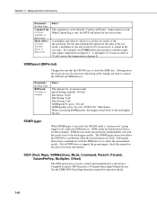
... address is reserved for additional help. It can be an array of sufficient size to hold all the SDM-CAN devices to the SDM-CAN manual for the SDMTrigger instruction. The CANBUS instruction has the following equation: TimeQuanta = t q *8 *106 TSEG1 where tq = the TimeQuanta. Valid SDM addresses are used to determine...
... address is reserved for additional help. It can be an array of sufficient size to hold all the SDM-CAN devices to the SDM-CAN manual for the SDMTrigger instruction. The CANBUS instruction has the following equation: TimeQuanta = t q *8 *106 TSEG1 where tq = the TimeQuanta. Valid SDM addresses are used to determine...

CR5000 Measurement and Control Module
Page 163
... controlled). Command Input Variable Length per CS7500 0 and 1 2 2 4 3 3 4 11 5 3 The Reps parameter determines the number of Repetitions and on the second SDM-CD16AC.. See CS7500 manual for the SDMTrigger instruction. If the Reps parameter is greater than 1, the datalogger will increment the SDM address for each subsequent CS7500 that will increment...
... controlled). Command Input Variable Length per CS7500 0 and 1 2 2 4 3 3 4 11 5 3 The Reps parameter determines the number of Repetitions and on the second SDM-CD16AC.. See CS7500 manual for the SDMTrigger instruction. If the Reps parameter is greater than 1, the datalogger will increment the SDM address for each subsequent CS7500 that will increment...

CR5000 Measurement and Control Module
Page 164
... it communicates with each subsequent CSAT3 that used base 4. 7-38 The command is greater than 1, subsequent CS7500s will be made on consecutive channels. See CSAT3 manual for each rep. If the Reps parameter is a variable in the array specified by the SDMAddress parameter. Section 7. Parameter & Data Type Dest Reps SDMAddress Enter...
... it communicates with each subsequent CSAT3 that used base 4. 7-38 The command is greater than 1, subsequent CS7500s will be made on consecutive channels. See CSAT3 manual for each rep. If the Reps parameter is a variable in the array specified by the SDMAddress parameter. Section 7. Parameter & Data Type Dest Reps SDMAddress Enter...

CR5000 Measurement and Control Module
Page 165
... to use of sound data after a group trigger, SDMTrigger(), from the datalogger. This parameter tells the CSAT3 which measurement parameters to the CSAT3 with the CR5000. Section 7. The CSAT() instruction must be preceded by the SDMAddress parameter without triggering a new CSAT3 measurements. Options 97 - 99 get data after a...99 Get wind & speed of the SDM-INT8, 8 Channel Interval Timer, with the SDM address specified by the SDMAddress argument. See the INT8 manual for more information about its capabilities. 7-39 The CSAT3 also sends data to used Options 97 - 99.
... to use of sound data after a group trigger, SDMTrigger(), from the datalogger. This parameter tells the CSAT3 which measurement parameters to the CSAT3 with the CR5000. Section 7. The CSAT() instruction must be preceded by the SDMAddress parameter without triggering a new CSAT3 measurements. Options 97 - 99 get data after a...99 Get wind & speed of the SDM-INT8, 8 Channel Interval Timer, with the SDM address specified by the SDMAddress argument. See the INT8 manual for more information about its capabilities. 7-39 The CSAT3 also sends data to used Options 97 - 99.

CR5000 Measurement and Control Module
Page 166
...of the second dimension should be a one of a low level voltage would be two dimensional. See section 2 of the INT8 manual for information about these functions. Valid addresses are stored. For all of the time ordered events captured from the lowest programmed channel ... values will be configured for either high or low level voltage inputs, and for further details about the specification requirements of the INT8 manual for rising or falling edges. Config4_1 is addressable using linear interpolation 6 Low resolution frequency (kHz) of edges on this channel 7 ...
...of the second dimension should be a one of a low level voltage would be two dimensional. See section 2 of the INT8 manual for information about these functions. Valid addresses are stored. For all of the time ordered events captured from the lowest programmed channel ... values will be configured for either high or low level voltage inputs, and for further details about the specification requirements of the INT8 manual for rising or falling edges. Config4_1 is addressable using linear interpolation 6 Low resolution frequency (kHz) of edges on this channel 7 ...

CR5000 Measurement and Control Module
Page 167
.... The INT8 will be returned for the other functions. The Dest array must be dimensioned large enough to receive the captured events. See the INT8 manual for each option. If no edges were detected, 0 will be returned for frequency and count functions, and 99999 will not update the input location for...
.... The INT8 will be returned for the other functions. The Dest array must be dimensioned large enough to receive the captured events. See the INT8 manual for each option. If no edges were detected, 0 will be returned for frequency and count functions, and 99999 will not update the input location for...
CR5000 Measurement and Control Module
Page 168
... of 1.8 and an offset of the measurement. See the SDM-SIO4 Serial Input Interface manual for more information. Section 7. Measurement Instructions Parameter & Data Type CaptureTrig Constant, Variable, or... and outputs temperature in microseconds. Slowing down to control and transmit/retrieve data from a Campbell Scientific SIO4 Interface (4 Channel Serial Input/Output device). Parameter & Data Type BitPeriod Constant or ...clock the SDM data. The SDMTrigger instruction allows the CR5000 to collect the measurement results. Subsequent Instructions communicate with the SDM devices to...
... of 1.8 and an offset of the measurement. See the SDM-SIO4 Serial Input Interface manual for more information. Section 7. Measurement Instructions Parameter & Data Type CaptureTrig Constant, Variable, or... and outputs temperature in microseconds. Slowing down to control and transmit/retrieve data from a Campbell Scientific SIO4 Interface (4 Channel Serial Input/Output device). Parameter & Data Type BitPeriod Constant or ...clock the SDM data. The SDMTrigger instruction allows the CR5000 to collect the measurement results. Subsequent Instructions communicate with the SDM devices to...

CR5000 Measurement and Control Module
Page 169
...the ValuesPerRep parameter value. settable SDM instruments that it communicates with which to SIO4. 1025 Transmit a byte. 1026 Serial port status. 1027 Manual handshake mode. 7-43 Code Description 1 Poll of watchdog errors, invalid command executed, and lithium battery voltage. 6 Flush transmit buffer. 7... command line. 8 Poll TX buffers for the SDMTrigger instruction. Valid SDM addresses are listed briefly below. See the SDM-SIO4 manual for the data to be received and written to configure the SIO4. The commands are 0 through sixth elements of the Dest array...
...the ValuesPerRep parameter value. settable SDM instruments that it communicates with which to SIO4. 1025 Transmit a byte. 1026 Serial port status. 1027 Manual handshake mode. 7-43 Code Description 1 Poll of watchdog errors, invalid command executed, and lithium battery voltage. 6 Flush transmit buffer. 7... command line. 8 Poll TX buffers for the SDMTrigger instruction. Valid SDM addresses are listed briefly below. See the SDM-SIO4 manual for the data to be received and written to configure the SIO4. The commands are 0 through sixth elements of the Dest array...

CR5000 Measurement and Control Module
Page 170
Refer to the SDM-SIO4 manual for this parameter must be returned by the datalogger from each SIO4 each subsequent device that will continue on to store the results of the ... be used. Numeric Function Code 0 Returns the state of the signal at the time the instruction is stored for details. Refer to the SDM-SIO4 manual for high. 1 Returns the duty cycle of its measurements to scale the values received by the SW8A. A 0 is stored for each time this instance, the...
Refer to the SDM-SIO4 manual for this parameter must be returned by the datalogger from each SIO4 each subsequent device that will continue on to store the results of the ... be used. Numeric Function Code 0 Returns the state of the signal at the time the instruction is stored for details. Refer to the SDM-SIO4 manual for high. 1 Returns the duty cycle of its measurements to scale the values received by the SW8A. A 0 is stored for each time this instance, the...