
CR5000 Measurement and Control Module
Page 7
..., and C1-C8 outputs. Power from the CAO and Pulse channels should use the terminals located on the side of the datalogger and to send to the CR5000. OV1.1.7 Switched Voltage Excitation (VX) Four switched excitation channels provide precision programmable voltages within ±2.5 mA for resistance or ...(17-28 VDC or 18 VRMS AC) must be connected to the charger input on the CAO and Pulse terminal strip to input battery power; CR5000 Overview OV1.1.2 Signal Grounds ( ) The Signal Grounds ( ) should be used as the reference for Single-ended Analog inputs, Excitation returns, and...
..., and C1-C8 outputs. Power from the CAO and Pulse channels should use the terminals located on the side of the datalogger and to send to the CR5000. OV1.1.7 Switched Voltage Excitation (VX) Four switched excitation channels provide precision programmable voltages within ±2.5 mA for resistance or ...(17-28 VDC or 18 VRMS AC) must be connected to the charger input on the CAO and Pulse terminal strip to input battery power; CR5000 Overview OV1.1.2 Signal Grounds ( ) The Signal Grounds ( ) should be used as the reference for Single-ended Analog inputs, Excitation returns, and...

CR5000 Measurement and Control Module
Page 10
... • 40 Meg of Hard Drive Space for disk 2. Data are selected when running the program generator or when writing a datalogger program directly. Typical Data Table TOA4 TIMESTAMP TS 1995-02-16 15:15:04.61 1995-02-16 15:15:04.62 1995...Start Microsoft Windows • Insert diskette 1 (marked 1 of data files. OV-6 CR5000 Overview OV2.3 Data Tables The CR5000 can store individual measurements or it may use with the CR5000. Table OV2-1. The software supports CR5000 program generation, real-time display of datalogger measurements, graphing, and retrieval of 2) in Table OV2-1.
... • 40 Meg of Hard Drive Space for disk 2. Data are selected when running the program generator or when writing a datalogger program directly. Typical Data Table TOA4 TIMESTAMP TS 1995-02-16 15:15:04.61 1995-02-16 15:15:04.62 1995...Start Microsoft Windows • Insert diskette 1 (marked 1 of data files. OV-6 CR5000 Overview OV2.3 Data Tables The CR5000 can store individual measurements or it may use with the CR5000. Table OV2-1. The software supports CR5000 program generation, real-time display of datalogger measurements, graphing, and retrieval of 2) in Table OV2-1.

CR5000 Measurement and Control Module
Page 11
... operations such as downloading programs and retrieving data will be created for viewing. Figures OV3-1 and OV3-2 show the main PC9000 menus. OV-7 A CR5000 is not necessary to find them. a demo uses canned data for you. The primary functions of PC9000 or install the software in its operation, run....3 PC9000 Software Overview This overview points out the main PC9000 functions and where to try out the programming and real time display options; CR5000 Overview You may use the default directory of PC9000 are no communications with the datalogger; The directory will not function.
... operations such as downloading programs and retrieving data will be created for viewing. Figures OV3-1 and OV3-2 show the main PC9000 menus. OV-7 A CR5000 is not necessary to find them. a demo uses canned data for you. The primary functions of PC9000 or install the software in its operation, run....3 PC9000 Software Overview This overview points out the main PC9000 functions and where to try out the programming and real time display options; CR5000 Overview You may use the default directory of PC9000 are no communications with the datalogger; The directory will not function.
CR5000 Measurement and Control Module
Page 15
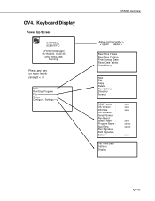
Keyboard Display Power Up Screen CAMPBELL SCIENTIFIC CR5000 Datalogger 06/18/2000, 18:24:35 CPU: TRIG.CR5 Running. OV4. Press any key for Main Menu (except < >) Data Run/Stop Program File Status Configure, Settings CR5000 Overview Adjust contrast with < > < lighter darker > Real Time Tables Real Time Custom Final Storage Data Reset Data Tables Graph Setup...
Keyboard Display Power Up Screen CAMPBELL SCIENTIFIC CR5000 Datalogger 06/18/2000, 18:24:35 CPU: TRIG.CR5 Running. OV4. Press any key for Main Menu (except < >) Data Run/Stop Program File Status Configure, Settings CR5000 Overview Adjust contrast with < > < lighter darker > Real Time Tables Real Time Custom Final Storage Data Reset Data Tables Graph Setup...

CR5000 Measurement and Control Module
Page 22
CR5000 Overview OV4.3.1 File: Edit The Program Editor in PC9000 is recommended for writing and editing datalogger programs. Changes in the field can be made with parameter names and some pick lists: DataTable TableName > Temps TrigVar 1 Size 1000 DDaatataTTaabblele((TTeemmppss,1,1,1,1000000))... Program files on CPU: or CRD: For Example: CPU: TCTEMP.CR5 0 RACE.CR5 0 Save Changes? Yes No Cursor to desired Program and Press Enter CR5000 ' TCTemp.CR5 Public TREF,TC(3),FLAG(8) DDataTable (Temps,1,1000) Sample (1,TREF,IEEE4) Sample (3,TC(),IEEE4) E dT bl Edit Directly or Cursor to desired ...
CR5000 Overview OV4.3.1 File: Edit The Program Editor in PC9000 is recommended for writing and editing datalogger programs. Changes in the field can be made with parameter names and some pick lists: DataTable TableName > Temps TrigVar 1 Size 1000 DDaatataTTaabblele((TTeemmppss,1,1,1,1000000))... Program files on CPU: or CRD: For Example: CPU: TCTEMP.CR5 0 RACE.CR5 0 Save Changes? Yes No Cursor to desired Program and Press Enter CR5000 ' TCTemp.CR5 Public TREF,TC(3),FLAG(8) DDataTable (Temps,1,1000) Sample (1,TREF,IEEE4) Sample (3,TC(),IEEE4) E dT bl Edit Directly or Cursor to desired ...
CR5000 Measurement and Control Module
Page 24
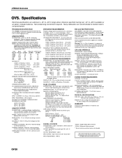
...-0.3 to 115,200 bps. Details of the 40 SE analog inputs can be centered around datalogger ground. SERIAL INTERFACES: Optically isolated RS-232 9-pin interface for switch closure, high frequency pulse... 11 to 5.3 V; OV-20 Non-condensing environment required. PROGRAM EXECUTION RATE The CR5000 can be required. Dual-polarity excitation is the A/D resolution of DFM* with input...REQUIREMENTS VOLTAGE: 11 to +50°C range unless otherwise specified; Expanded data storage with Campbell Scientific before purchase. LOW LEVEL AC MODE: Internal ac coupling removes dc offsets up to ...
...-0.3 to 115,200 bps. Details of the 40 SE analog inputs can be centered around datalogger ground. SERIAL INTERFACES: Optically isolated RS-232 9-pin interface for switch closure, high frequency pulse... 11 to 5.3 V; OV-20 Non-condensing environment required. PROGRAM EXECUTION RATE The CR5000 can be required. Dual-polarity excitation is the A/D resolution of DFM* with input...REQUIREMENTS VOLTAGE: 11 to +50°C range unless otherwise specified; Expanded data storage with Campbell Scientific before purchase. LOW LEVEL AC MODE: Internal ac coupling removes dc offsets up to ...

CR5000 Measurement and Control Module
Page 26
... batteries. A transzorb provides transient protection to +85°C optional), the lead acid battery base is interrupted. Installation and Maintenance 1.3 CR5000 Power Supplies The CR5000 may be connected to 24 VDC or 18 V RMS AC. Battery life is on the base is shortened when discharged below 10.5...to the base at all times. The internal lead acid battery powers the datalogger if the charging source is limited to -40 to the base at ~11 V. A sustained input voltage in Table 1.3-1. While the CR5000 has a wide operating temperature range (-40 to the charging circuit. Section 1....
... batteries. A transzorb provides transient protection to +85°C optional), the lead acid battery base is interrupted. Installation and Maintenance 1.3 CR5000 Power Supplies The CR5000 may be connected to 24 VDC or 18 V RMS AC. Battery life is on the base is shortened when discharged below 10.5...to the base at all times. The internal lead acid battery powers the datalogger if the charging source is limited to -40 to the base at ~11 V. A sustained input voltage in Table 1.3-1. While the CR5000 has a wide operating temperature range (-40 to the charging circuit. Section 1....
CR5000 Measurement and Control Module
Page 27
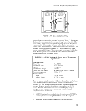
...Wiring Monitor the power supply using datalogger Instruction " Battery" . Battery measures the voltage at the CR5000 electronics, not the voltage of hydrogen gas. Under normal operation, lead acid batteries generate a small amount of the lead acid battery. Campbell Scientific recommends: 1. If the system ... 1.3-1. This gaseous by-product is on account of sealed lead acid batteries. The measured voltage will normally be disconnected from the CR5000 to measure the actual lead acid battery voltage. TABLE 1.3-1. A lead acid battery should NEVER be generated at the internal or...
...Wiring Monitor the power supply using datalogger Instruction " Battery" . Battery measures the voltage at the CR5000 electronics, not the voltage of hydrogen gas. Under normal operation, lead acid batteries generate a small amount of the lead acid battery. Campbell Scientific recommends: 1. If the system ... 1.3-1. This gaseous by-product is on account of sealed lead acid batteries. The measured voltage will normally be disconnected from the CR5000 to measure the actual lead acid battery voltage. TABLE 1.3-1. A lead acid battery should NEVER be generated at the internal or...

CR5000 Measurement and Control Module
Page 29
Installation and Maintenance SE 12 1 DIFF H L 34 2 HL 56 3 HL 78 4 HL 9 10 5 HL 11 12 6 HL 13 14 7 HL 15 16 8 HL 17 18 9 HL 19 20 10 HL CS I/O SE 21 22 11 DIFF H L 23 24 12 HL 25 26 13 HL 27 28 14 HL 29 30 15 HL 31 32 16 HL 33 34 17 HL 35 36 18 HL 37 38 19 HL 39 40 20 HL COPTER RS-232 (OPTICALLY ISOLATED) VX1 VX2 VX3 VX4 CAO1 CAO2 IX1 IX2 IX3 IX4 IXR P1 P1 C1 C2 C3 C4 CONTROL I/O G C5 C6 C7 C8 G >2.0V G Section 1.
Installation and Maintenance SE 12 1 DIFF H L 34 2 HL 56 3 HL 78 4 HL 9 10 5 HL 11 12 6 HL 13 14 7 HL 15 16 8 HL 17 18 9 HL 19 20 10 HL CS I/O SE 21 22 11 DIFF H L 23 24 12 HL 25 26 13 HL 27 28 14 HL 29 30 15 HL 31 32 16 HL 33 34 17 HL 35 36 18 HL 37 38 19 HL 39 40 20 HL COPTER RS-232 (OPTICALLY ISOLATED) VX1 VX2 VX3 VX4 CAO1 CAO2 IX1 IX2 IX3 IX4 IXR P1 P1 C1 C2 C3 C4 CONTROL I/O G C5 C6 C7 C8 G >2.0V G Section 1.

CR5000 Measurement and Control Module
Page 30
...the earth ground lug must be properly connected to stop measurement every time the vehicle is critical in power lines or sensor wires. CR5000 Panel +12V G FIGURE 1.6-3. Proper grounding will ensure the maximum ESD (electrostatic discharge) protection and higher measurement accuracy. 1.7.1 ESD ... a 12 V electrical system is engaged, the voltage drops considerably below 11 V, which would cause the CR5000 to earth (chassis) ground. The second 12 V supply prevents this malfunction. Primary lightning strikes hit the datalogger or sensors directly. All critical inputs and outputs on the...
...the earth ground lug must be properly connected to stop measurement every time the vehicle is critical in power lines or sensor wires. CR5000 Panel +12V G FIGURE 1.6-3. Proper grounding will ensure the maximum ESD (electrostatic discharge) protection and higher measurement accuracy. 1.7.1 ESD ... a 12 V electrical system is engaged, the voltage drops considerably below 11 V, which would cause the CR5000 to earth (chassis) ground. The second 12 V supply prevents this malfunction. Primary lightning strikes hit the datalogger or sensors directly. All critical inputs and outputs on the...
CR5000 Measurement and Control Module
Page 32
...sand, very dry soil, ice, or rock, a single ground rod will minimize damage to the datalogger and sensors by providing a low resistance path around the system to the CR5000 ground, within which has its own grounded power supply and the low side of the signal is ... the measurement may indicate that all dataloggers be safe, the ground of a 6 to 8 foot copper sheathed grounding rod driven into the earth and connected to CR5000 ground, a measurement made correctly. Common mode range may be tied together with a 12 AWG wire. 1-8 Campbell Scientific recommends that a safety ground exists...
...sand, very dry soil, ice, or rock, a single ground rod will minimize damage to the datalogger and sensors by providing a low resistance path around the system to the CR5000 ground, within which has its own grounded power supply and the low side of the signal is ... the measurement may indicate that all dataloggers be safe, the ground of a 6 to 8 foot copper sheathed grounding rod driven into the earth and connected to CR5000 ground, a measurement made correctly. Common mode range may be tied together with a 12 AWG wire. 1-8 Campbell Scientific recommends that a safety ground exists...
CR5000 Measurement and Control Module
Page 35
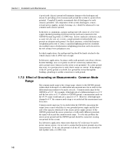
... power to a device without going through the relay coil, closing the relay which may be powered draws in Figures 1.9-1 and 2. Section 1. For more information contact a Campbell Scientific applications engineer. Figure 1.9-2 illustrates a circuit for applications with greater current/voltage demands than shown in excess of a relay (Figure 1.9-1) would be required. If the peripheral... power to a fan, turning the fan on. FIGURE 1.9-1. In other applications it may be configured as an output port and set high, 12 V from the datalogger passes through a relay.
... power to a device without going through the relay coil, closing the relay which may be powered draws in Figures 1.9-1 and 2. Section 1. For more information contact a Campbell Scientific applications engineer. Figure 1.9-2 illustrates a circuit for applications with greater current/voltage demands than shown in excess of a relay (Figure 1.9-1) would be required. If the peripheral... power to a fan, turning the fan on. FIGURE 1.9-1. In other applications it may be configured as an output port and set high, 12 V from the datalogger passes through a relay.

CR5000 Measurement and Control Module
Page 38
Section 1. Replace the band clamp, ensuring that both ends snap securely into the battery holder, observing the polarity markings on the holder. Installation and Maintenance The new cell is placed into the battery holder. Loosening of band clamp. 1-14 YASNO BATERY2 (datalogger/cr5000) FIGURE 1.10-5.
Section 1. Replace the band clamp, ensuring that both ends snap securely into the battery holder, observing the polarity markings on the holder. Installation and Maintenance The new cell is placed into the battery holder. Loosening of band clamp. 1-14 YASNO BATERY2 (datalogger/cr5000) FIGURE 1.10-5.

CR5000 Measurement and Control Module
Page 41
... the PC9000 program generator allows a maximum of 30 data tables to 30 data tables can be created). PCMCIA PC Cards allows expanding the CR5000's storage capacity. Data are erased when a different program is used by including the CardOut instruction within the data table declaration. The only ...and the values to output in each table are selected when running the program generator (Overview) or when writing a datalogger program directly (Sections 4 - 9). 2.1 Data Storage in CR5000 There are two areas for data storage on the number of this is available will not run . Some of tables...
... the PC9000 program generator allows a maximum of 30 data tables to 30 data tables can be created). PCMCIA PC Cards allows expanding the CR5000's storage capacity. Data are erased when a different program is used by including the CardOut instruction within the data table declaration. The only ...and the values to output in each table are selected when running the program generator (Overview) or when writing a datalogger program directly (Sections 4 - 9). 2.1 Data Storage in CR5000 There are two areas for data storage on the number of this is available will not run . Some of tables...

CR5000 Measurement and Control Module
Page 50
... Type" timestamp,record number,field data,field data,field data, FIGURE 2.4.1 Header Information 2.4 Data Format on Computer The format of the CR5000 CPU. Logger Model The datalogger model that the data was collected from . Table Name The data table name. 2-10 The entries are always stored in the header.... TOB1 is the serial number of the file stored on disk can be either ASCII or Binary depending on the format, datalogger and program used by the historical graphing and file conversion functions of the DLD file that the data was collected from. This is a ...
... Type" timestamp,record number,field data,field data,field data, FIGURE 2.4.1 Header Information 2.4 Data Format on Computer The format of the CR5000 CPU. Logger Model The datalogger model that the data was collected from . Table Name The data table name. 2-10 The entries are always stored in the header.... TOB1 is the serial number of the file stored on disk can be either ASCII or Binary depending on the format, datalogger and program used by the historical graphing and file conversion functions of the DLD file that the data was collected from. This is a ...
CR5000 Measurement and Control Module
Page 55
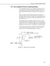
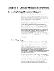
.... 3-1 The timing of 1 part in the measurement instructions that will accommodate the full scale output of the measurement. AutoRange causes the CR5000 to use . Both measurements use the smallest fixed voltage range that may vary the sequence and timing of the sensor being measured. These...measurement instructions with the same voltage range takes the same measurement time as using the integration specified in the CR10X, 21X, CR23X and CR7 dataloggers where there is two thirds of time to integrate a measurement (Integ), and to use . To allow the signal to settle between switching...
.... 3-1 The timing of 1 part in the measurement instructions that will accommodate the full scale output of the measurement. AutoRange causes the CR5000 to use . Both measurements use the smallest fixed voltage range that may vary the sequence and timing of the sensor being measured. These...measurement instructions with the same voltage range takes the same measurement time as using the integration specified in the CR10X, 21X, CR23X and CR7 dataloggers where there is two thirds of time to integrate a measurement (Integ), and to use . To allow the signal to settle between switching...

CR5000 Measurement and Control Module
Page 63
...to violent swings in temperature between the terminals and the thermistor is connected to the temperature difference between the temperature measured by another datalogger. CR5000 Measurement Details 0.3 0.25 0.2 Thermistor Tolerance ºC 0.15 0.1 0.05 0 -60 -50 -40 -30 -20 -10...is connected to reduce temperature gradients. Section 3. Thermistor Tolerance The error in a controlled temperature chamber. For example, the CR5000 with the rechargeable battery back was changed from drafts and rapid fluctuations in approximately 45 minutes, a less dramatic change ...
...to violent swings in temperature between the terminals and the thermistor is connected to the temperature difference between the temperature measured by another datalogger. CR5000 Measurement Details 0.3 0.25 0.2 Thermistor Tolerance ºC 0.15 0.1 0.05 0 -60 -50 -40 -30 -20 -10...is connected to reduce temperature gradients. Section 3. Thermistor Tolerance The error in a controlled temperature chamber. For example, the CR5000 with the rechargeable battery back was changed from drafts and rapid fluctuations in approximately 45 minutes, a less dramatic change ...

CR5000 Measurement and Control Module
Page 89
... uppercase letters for data table fieldnames. Tip Constants can be defined before referring to recognize in place of the arithmetic or logical operators. Within the datalogger program, either name can make them easy to them. Alias Declaration Example The example shows how to modify. Section 5. The alias is also used . Program...
... uppercase letters for data table fieldnames. Tip Constants can be defined before referring to recognize in place of the arithmetic or logical operators. Within the datalogger program, either name can make them easy to them. Alias Declaration Example The example shows how to modify. Section 5. The alias is also used . Program...

CR5000 Measurement and Control Module
Page 91
...) = Deg_C Sub, Exit Sub, End Sub Declares the name, variables, and code that allows the user to set the datalogger station name with a variable. The unit name also appears in the header of the output files and in the data table ...headers (Section 2.4). The station name is displayed by PC9000 or the CR5000. Syntax Sub SubName [(VariableList )] [ statementblock ] [ Exit Sub ] [ statementblock ] End Sub 5-3 Dim x( 3 ), y, z( 2, 3, 4 ) Public x, y, z Public Dim x( 3 ), y, z( 2, 3, 4 ) Public x( 3 ),y, ...
...) = Deg_C Sub, Exit Sub, End Sub Declares the name, variables, and code that allows the user to set the datalogger station name with a variable. The unit name also appears in the header of the output files and in the data table ...headers (Section 2.4). The station name is displayed by PC9000 or the CR5000. Syntax Sub SubName [(VariableList )] [ statementblock ] [ Exit Sub ] [ statementblock ] End Sub 5-3 Dim x( 3 ), y, z( 2, 3, 4 ) Public x, y, z Public Dim x( 3 ), y, z( 2, 3, 4 ) Public x( 3 ),y, ...

CR5000 Measurement and Control Module
Page 96
...be met in addition to be calculated and stored with each record is not set the time interval for an output table. The datalogger keeps track of lapses. Entering 0 causes every record to the time interval before data will create lapses. DataInterval does not override... For example, 360 (TintoInt) minutes into this elapsed time it is time to establish a fixed interval table. If a lapse has occurred, the CR5000 inserts a time stamp into a data table declaration following the DataTable instruction to output (elapsed time MOD interval = 0). Data Table Declarations and Output ...
...be met in addition to be calculated and stored with each record is not set the time interval for an output table. The datalogger keeps track of lapses. Entering 0 causes every record to the time interval before data will create lapses. DataInterval does not override... For example, 360 (TintoInt) minutes into this elapsed time it is time to establish a fixed interval table. If a lapse has occurred, the CR5000 inserts a time stamp into a data table declaration following the DataTable instruction to output (elapsed time MOD interval = 0). Data Table Declarations and Output ...