
CR9000X Measurement and Control System
Page 3
...Port of Entry) INCOTERM® 2010, prepaid. This warranty is in lieu of all other locations, Campbell will return such products by surface carrier prepaid within the continental United States of America. Campbell's obligation under this warranty is limited to repairing or replacing (at Campbell.... Warranty The CR9000X Measurement and Control System is warranted for installation services performed by Campbell such as programming to customer specifications, electrical connections to products manufactured by Campbell, and product specific training, is part of Campbell's product warranty....
...Port of Entry) INCOTERM® 2010, prepaid. This warranty is in lieu of all other locations, Campbell will return such products by surface carrier prepaid within the continental United States of America. Campbell's obligation under this warranty is limited to repairing or replacing (at Campbell.... Warranty The CR9000X Measurement and Control System is warranted for installation services performed by Campbell such as programming to customer specifications, electrical connections to products manufactured by Campbell, and product specific training, is part of Campbell's product warranty....

CR9000X Measurement and Control System
Page 5
....3 Connecting the RS232 Port/ Card Installation QS-2 QS1.4 Powering the Logger QS-3 QS1.5 Setting Up Serial Communications QS-3 QS1.6 Setting Up IP Communications QS-9 QS2. Use the PDF reader bookmarks tab for links to Vehicle Power Supply 1-5 1.2.3 Solar Panels 1-6 1.2.4 External Battery Connection 1-6 1.2.5 Safety Precautions 1-7 i Program Generator Basics QS-12 QS2.1 Program Generator Summary Window QS-12 QS2.2 Program Generator Configuration Window QS-13 QS2.3 Program Generator Scan Window QS-14 QS2.4 Program Generator Output Table Window QS...
....3 Connecting the RS232 Port/ Card Installation QS-2 QS1.4 Powering the Logger QS-3 QS1.5 Setting Up Serial Communications QS-3 QS1.6 Setting Up IP Communications QS-9 QS2. Use the PDF reader bookmarks tab for links to Vehicle Power Supply 1-5 1.2.3 Solar Panels 1-6 1.2.4 External Battery Connection 1-6 1.2.5 Safety Precautions 1-7 i Program Generator Basics QS-12 QS2.1 Program Generator Summary Window QS-12 QS2.2 Program Generator Configuration Window QS-13 QS2.3 Program Generator Scan Window QS-14 QS2.4 Program Generator Output Table Window QS...
CR9000X Measurement and Control System
Page 41
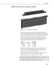
... the most sensitive range is 100,000 samples per second. The maximum aggregate throughput for thermocouple measurements. Resolution on all modules is 1.6 μV. See Section 3.1 Measurements using the CR9041 A/D for Instruction details. The CR9051E supports the same instruction set as to data logger ground is powered off. OV-9 Another difference from the CR9000X chassis. All inputs on the CR9050(E), CR9051E...
... the most sensitive range is 100,000 samples per second. The maximum aggregate throughput for thermocouple measurements. Resolution on all modules is 1.6 μV. See Section 3.1 Measurements using the CR9041 A/D for Instruction details. The CR9051E supports the same instruction set as to data logger ground is powered off. OV-9 Another difference from the CR9000X chassis. All inputs on the CR9050(E), CR9051E...
CR9000X Measurement and Control System
Page 49
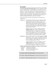
... volts. See Section 9.2 Data Logger Status/ Control for measurement details. The resolution of the frequency measurement is pulled to output Counts or Signal Frequency. These twelve channels are signals that have transitions from below 1.5 volts to 5 MHz can be connected between the Pulse port and ground. When the switch is open, the port is 1/scan interval (e.g., a PulseCount instruction in a 1 second scan has a frequency resolution of 1 Hz...
... volts. See Section 9.2 Data Logger Status/ Control for measurement details. The resolution of the frequency measurement is pulled to output Counts or Signal Frequency. These twelve channels are signals that have transitions from below 1.5 volts to 5 MHz can be connected between the Pulse port and ground. When the switch is open, the port is 1/scan interval (e.g., a PulseCount instruction in a 1 second scan has a frequency resolution of 1 Hz...
CR9000X Measurement and Control System
Page 51
.... CR9071 SUPPORTED MEASUREMENT/CONTORL INSTRUCTIONS: PulseCount Count Pulses or Frequency ReadI/O Read State of I/O Channels TimerIO Interval and Timing Measurements WaitDigTrig Trigger Measurement Scan WriteI/O Set State of low level AC signals from below 1.5 volts to output in Counts or Signal Frequency. The dry contact switch should be configured to above 3.5 volts. Channels 1 through 12 can be connected between the Pulse port and ground. Channels 9 through...
.... CR9071 SUPPORTED MEASUREMENT/CONTORL INSTRUCTIONS: PulseCount Count Pulses or Frequency ReadI/O Read State of I/O Channels TimerIO Interval and Timing Measurements WaitDigTrig Trigger Measurement Scan WriteI/O Set State of low level AC signals from below 1.5 volts to output in Counts or Signal Frequency. The dry contact switch should be configured to above 3.5 volts. Channels 1 through 12 can be connected between the Pulse port and ground. Channels 9 through...
CR9000X Measurement and Control System
Page 54
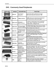
...-Amp resolution). Receives signals from GPS satellites for bridge measurements. Overview OV3. Four configurable serial RS232 ports that supply completion resistors for currents). The INT8 calculates period, pulse width, frequency, counts, or time interval with a PRT, for Thermocouples Solid state multiplexer, with a 1 microsec resolution. Maximum input frequency: 100 Hz AM25T 25 Channel Multiplexer for measuring thermocouple outputs. AM16/32 16 Bank (4 Wires) or...
...-Amp resolution). Receives signals from GPS satellites for bridge measurements. Overview OV3. Four configurable serial RS232 ports that supply completion resistors for currents). The INT8 calculates period, pulse width, frequency, counts, or time interval with a PRT, for Thermocouples Solid state multiplexer, with a 1 microsec resolution. Maximum input frequency: 100 Hz AM25T 25 Channel Multiplexer for measuring thermocouple outputs. AM16/32 16 Bank (4 Wires) or...

CR9000X Measurement and Control System
Page 71
.... 1.5 Use of Digital Control Ports for altering an external circuit as a means of the differential input connected to ground to ensure the signal remains within the operational voltage range. Figure 1.5-1 is used (Part No. 2N2222). Typical connection for switching the relays. Section 1. FIGURE 1.5-1. The example shows a DC fan motor and 12 V battery in conjunction with a 0-5 V logic signal are not used directly to actually power the relay. If a CR9000X is a schematic representation...
.... 1.5 Use of Digital Control Ports for altering an external circuit as a means of the differential input connected to ground to ensure the signal remains within the operational voltage range. Figure 1.5-1 is used (Part No. 2N2222). Typical connection for switching the relays. Section 1. FIGURE 1.5-1. The example shows a DC fan motor and 12 V battery in conjunction with a 0-5 V logic signal are not used directly to actually power the relay. If a CR9000X is a schematic representation...

CR9000X Measurement and Control System
Page 73
... using a PCMCIA card, the DataTable instruction's Size parameter sets the size of Internal SDRAM. SRAM, ATA Flash, and ATA hard disk cards, up to 30 Tables can be stored to the PC card. The Cards normally should normally only be used as a buffer area for the Program Files and the sensor calibration files. Section 2. Data Storage and Retrieval The CR9000X can be used via a Compact Flash Adapter (contact Campbell Scientific). Data...
... using a PCMCIA card, the DataTable instruction's Size parameter sets the size of Internal SDRAM. SRAM, ATA Flash, and ATA hard disk cards, up to 30 Tables can be stored to the PC card. The Cards normally should normally only be used as a buffer area for the Program Files and the sensor calibration files. Section 2. Data Storage and Retrieval The CR9000X can be used via a Compact Flash Adapter (contact Campbell Scientific). Data...
CR9000X Measurement and Control System
Page 83
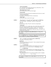
... the data was stored. "Program File" The name of the CR9000X's CPU. Each field that is the serial number of the program file that was used when the field was collected from. See Table 4.3-1 Output Processing Abbreviations for a listing of the 3 letter mnemonics. 2-11 See the FieldNames topic in Section 6.4 Output Processing Instructions and the Alias topic in the program with the Units...
... the data was stored. "Program File" The name of the CR9000X's CPU. Each field that is the serial number of the program file that was used when the field was collected from. See Table 4.3-1 Output Processing Abbreviations for a listing of the 3 letter mnemonics. 2-11 See the FieldNames topic in Section 6.4 Output Processing Instructions and the Alias topic in the program with the Units...

CR9000X Measurement and Control System
Page 90
... 5 mV signal will be measured as it delays the same time after the reversal as 5.005 mV. Reversing the inputs of time required for the signal to a new channel or switches on the excitation for the 200 and 50 mV ranges, are four parameters in the sensor, wiring, and measurement... is always a setup time for the CR9000X to settle to the channel: 3-2 Section 3. Using a delay increases the time required for each instruction.) There are the minimum required for each measurement. One measurement is made with the excitation voltage with the polarity programmed and a second ...
... 5 mV signal will be measured as it delays the same time after the reversal as 5.005 mV. Reversing the inputs of time required for the signal to a new channel or switches on the excitation for the 200 and 50 mV ranges, are four parameters in the sensor, wiring, and measurement... is always a setup time for the CR9000X to settle to the channel: 3-2 Section 3. Using a delay increases the time required for each instruction.) There are the minimum required for each measurement. One measurement is made with the excitation voltage with the polarity programmed and a second ...
CR9000X Measurement and Control System
Page 129
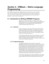
... the user with either will create a program template from which to start . The Quickstart Tutorial, works through a measurement example using the CRBASIC Program Editor. 4.1.2 Program Generator The CR9000X Program Generator is entered, either Short Cut, Program Generator, or the CRBASIC Editor. When as much information as a wiring diagram that has some similarities to choose. There are created with lists of predefined measurement, processing, and control algorithms...
... the user with either will create a program template from which to start . The Quickstart Tutorial, works through a measurement example using the CRBASIC Program Editor. 4.1.2 Program Generator The CR9000X Program Generator is entered, either Short Cut, Program Generator, or the CRBASIC Editor. When as much information as a wiring diagram that has some similarities to choose. There are created with lists of predefined measurement, processing, and control algorithms...
CR9000X Measurement and Control System
Page 243
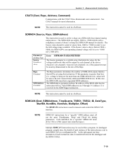
... (millivolts) that will be set the voltage on a SDM-AO4 four channel analog output device. At datalogger program compile time, the details of each instance of SDM-AO4 output channles that will be output by each instruction, data is used within a program. Reps Constant SDMAddress Constant The Reps parameter determines the number of the instruction are 0 through 14. Measurement Instructions CSAT3 (Dest, Reps, Address...
... (millivolts) that will be set the voltage on a SDM-AO4 four channel analog output device. At datalogger program compile time, the details of each instance of SDM-AO4 output channles that will be output by each instruction, data is used within a program. Reps Constant SDMAddress Constant The Reps parameter determines the number of the instruction are 0 through 14. Measurement Instructions CSAT3 (Dest, Reps, Address...

CR9000X Measurement and Control System
Page 252
... between the last edge on channel 1 and the edge on changing the INT8 address. See the SDM-INT8 manual for the Measurement of high and low level voltage signals. Funct8_5 is a Synchronous Device for more information about its capabilities. The SDM-INT8 is a four digit code to program the timing functions of the 8 input channels can be configured for either high...
... between the last edge on channel 1 and the edge on changing the INT8 address. See the SDM-INT8 manual for the Measurement of high and low level voltage signals. Funct8_5 is a Synchronous Device for more information about its capabilities. The SDM-INT8 is a four digit code to program the timing functions of the 8 input channels can be configured for either high...
CR9000X Measurement and Control System
Page 360
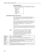
... be used . Program Control Instructions Data Statement Examples This example uses Data to hold the data values and Read to transfer the values to be set . Channels 1 through 16 are Switched Excitation channels Excitation voltage to delay the measurement task sequencer after the Excite instruction is not exceeded, there will remain at any signal degradation over time. Compliance current for the time specified by the Scan instruction. The...
... be used . Program Control Instructions Data Statement Examples This example uses Data to hold the data values and Read to transfer the values to be set . Channels 1 through 16 are Switched Excitation channels Excitation voltage to delay the measurement task sequencer after the Excite instruction is not exceeded, there will remain at any signal degradation over time. Compliance current for the time specified by the Scan instruction. The...

CR9000X Measurement and Control System
Page 366
... errors in CSI's software packages. When writing a program using a Shunt Calibration, the Reps parameter for Shunt Calibration StrainCalc (uSDest(), Reps, mVpV(), Zero_mVV(), BrConfig, GF_adj(), v) FieldCalStrain(13, uSDest(), Reps, GF_Adj(), 0, Mode, KnownR, Index, NumAvg, GF_Raw(), 0) Remarks This instruction is represented by changing the value of the Source_mVpV variable array, 2. The Reps parameter value should be initialized to the size of the Mode...
... errors in CSI's software packages. When writing a program using a Shunt Calibration, the Reps parameter for Shunt Calibration StrainCalc (uSDest(), Reps, mVpV(), Zero_mVV(), BrConfig, GF_adj(), v) FieldCalStrain(13, uSDest(), Reps, GF_Adj(), 0, Mode, KnownR, Index, NumAvg, GF_Raw(), 0) Remarks This instruction is represented by changing the value of the Source_mVpV variable array, 2. The Reps parameter value should be initialized to the size of the Mode...
CR9000X Measurement and Control System
Page 376
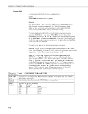
... units for the time parameters. If the "2" input has a voltage greater than 2 volts applied, the CR9000X will set up the CR9000X to power up in the past when PowerOff is extremely useful if the program executes the PowerOff instruction immediately or after a short measurement period. If StartTime is in response to power up . The interval allows the CR9000X to turn the CR9000X off CR9000X power. Program Control Instructions Power Off Used...
... units for the time parameters. If the "2" input has a voltage greater than 2 volts applied, the CR9000X will set up the CR9000X to power up in the past when PowerOff is extremely useful if the program executes the PowerOff instruction immediately or after a short measurement period. If StartTime is in response to power up . The interval allows the CR9000X to turn the CR9000X off CR9000X power. Program Control Instructions Power Off Used...

CR9000X Measurement and Control System
Page 417
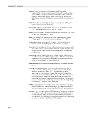
... viewed by PC software. Replace the lithium battery if Type of the 3.3 volt lithium battery. However, be accessed from the Status Table. Table D-1 lists the parameters in the designated slot #. Value is desired. Click the refresh button each . Operating System Signature Shows the serial number of comments added or non-functional changes to LoggerNetTM / PC400 / RTDAQ / PC200W: (| Datalogger | Station Status). Appendix D. Time this set...
... viewed by PC software. Replace the lithium battery if Type of the 3.3 volt lithium battery. However, be accessed from the Status Table. Table D-1 lists the parameters in the designated slot #. Value is desired. Click the refresh button each . Operating System Signature Shows the serial number of comments added or non-functional changes to LoggerNetTM / PC400 / RTDAQ / PC200W: (| Datalogger | Station Status). Appendix D. Time this set...
CR9000X Measurement and Control System
Page 426
... be Input Storage for the parameters by the program entered in the ID Field of processed summaries to internet protocol (IP). E-6 Transfer is the Greek letter Omega (Ω). 1 Ω equals the ratio of a particular data table record. Symbol is controlled by displaying the parameter number in the datalogger. The transfer of the display. output interval the time interval between Campbell Scientific instrumentation...
... be Input Storage for the parameters by the program entered in the ID Field of processed summaries to internet protocol (IP). E-6 Transfer is the Greek letter Omega (Ω). 1 Ω equals the ratio of a particular data table record. Symbol is controlled by displaying the parameter number in the datalogger. The transfer of the display. output interval the time interval between Campbell Scientific instrumentation...

CR9000X Measurement and Control System
Page 430
... concern, but normally indicates the user should cause increasing alarm since it indicates a hardware or software problem may be constructed for most datalogger applications using AC line power, an AC/AC or AC/DC wall adapter, a charge controller, and a rechargeable battery. Do not connect high-level VAC directly to reset the processor and program execution. The CR1000 operates with a Campbell Scientific applications engineer. It can cause...
... concern, but normally indicates the user should cause increasing alarm since it indicates a hardware or software problem may be constructed for most datalogger applications using AC line power, an AC/AC or AC/DC wall adapter, a charge controller, and a rechargeable battery. Do not connect high-level VAC directly to reset the processor and program execution. The CR1000 operates with a Campbell Scientific applications engineer. It can cause...

CR9000X Measurement and Control System
Page 439
... SDM-CVO4, 7-26 SDMINT8 Interval Timer Instruction, 7-27 SDMIO16 Instruction, 7-30 SDMSIO4 Instruction, 7-31 SDMSpeed Instruction, 7-32 SDMSW8A, 7-31 SDMTrigger Instruction, 7-33 SDMX50, 7-33 SecsSince1990, 9-50 Seebeck Effect, E-8 Select Case, 9-17 Send, E-8 Sensor Calibration File, 9-28 Serial, E-8 Serial Communications Set-up, QS-3 Serial Input/Output, 7-31 Serial Sensor Measurement, 7-42 SerialInput Instruction, 7-42 Server, OV-24 Settling Time, 3-2, 3-8, 3-9 Sgn Function, Sign of Number, 8-33 Short Cut, OV...
... SDM-CVO4, 7-26 SDMINT8 Interval Timer Instruction, 7-27 SDMIO16 Instruction, 7-30 SDMSIO4 Instruction, 7-31 SDMSpeed Instruction, 7-32 SDMSW8A, 7-31 SDMTrigger Instruction, 7-33 SDMX50, 7-33 SecsSince1990, 9-50 Seebeck Effect, E-8 Select Case, 9-17 Send, E-8 Sensor Calibration File, 9-28 Serial, E-8 Serial Communications Set-up, QS-3 Serial Input/Output, 7-31 Serial Sensor Measurement, 7-42 SerialInput Instruction, 7-42 Server, OV-24 Settling Time, 3-2, 3-8, 3-9 Sgn Function, Sign of Number, 8-33 Short Cut, OV...
