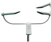

PWS100 Present Weather Sensor
Page 3
... installation services performed by surface carrier prepaid within the continental United States of all other warranties, expressed or implied. The warranty for any products which shall be free from date of shipment unless otherwise specified in lieu of America. Batteries, fine-wire thermocouples, desiccant, and other locations, Campbell will return such products by Campbell such as programming to customer specifications...
... installation services performed by surface carrier prepaid within the continental United States of all other warranties, expressed or implied. The warranty for any products which shall be free from date of shipment unless otherwise specified in lieu of America. Batteries, fine-wire thermocouples, desiccant, and other locations, Campbell will return such products by Campbell such as programming to customer specifications...

PWS100 Present Weather Sensor
Page 6
Operation 7-1 7.1 Introduction 7-1 7.2 PWS100 Configuration 7-1 7.2.1 Using the Present Weather Viewer Program 7-1 7.3 Terminal Mode 7-2 7.3.1 Using the Help Command 7-3 7.3.2 Entering / Exiting the Menu System 7-3 7.3.3 Message Polling 7-4 7.4 PWS100 Menu System 7-4 7.4.1 Top Menu Options 0, 1 and 2 (Message n 7-5 7.4.1.1 Message 0 (the Default Output 7-9 7.4.1.2 Message Field 1 and 2 User Defined Message 7-9 7.4.1.3 Message Field 10 To 19 Fixed Messages 7-10 7.4.1.4 Message Field 20 Visibility Range (m 7-10 7.4.1.5 Message Field 21 Present Weather Code (WMO 7-10 7.4.1.6 ...
Operation 7-1 7.1 Introduction 7-1 7.2 PWS100 Configuration 7-1 7.2.1 Using the Present Weather Viewer Program 7-1 7.3 Terminal Mode 7-2 7.3.1 Using the Help Command 7-3 7.3.2 Entering / Exiting the Menu System 7-3 7.3.3 Message Polling 7-4 7.4 PWS100 Menu System 7-4 7.4.1 Top Menu Options 0, 1 and 2 (Message n 7-5 7.4.1.1 Message 0 (the Default Output 7-9 7.4.1.2 Message Field 1 and 2 User Defined Message 7-9 7.4.1.3 Message Field 10 To 19 Fixed Messages 7-10 7.4.1.4 Message Field 20 Visibility Range (m 7-10 7.4.1.5 Message Field 21 Present Weather Code (WMO 7-10 7.4.1.6 ...

PWS100 Present Weather Sensor
Page 7
... 7.6.1 Setting and Viewing Weather Parameters 7-40 7.6.2 Receiving Data from Remote Sensors 7-41 7.7 System Configuration Commands 7-41 7.7.1 Setting System Parameters 7-41 7.8 Maintenance Commands 7-43 7.8.1 Loading a New OS 7-43 7.8.2 Running a Diagnostic Test 7-44 7.8.3 Running the Calibration 7-45 7.8.4 Rotating the Calibration Disc 7-45 7.9 Other Commands 7-45 7.9.1 Setting the Time and Date 7-45 7.9.2 Resetting the System 7-46 7.10 Connecting the PWS100 to a Datalogger 7-46 7.10.1 Connections 7-46 7.10.2 Example Logger Programs...
... 7.6.1 Setting and Viewing Weather Parameters 7-40 7.6.2 Receiving Data from Remote Sensors 7-41 7.7 System Configuration Commands 7-41 7.7.1 Setting System Parameters 7-41 7.8 Maintenance Commands 7-43 7.8.1 Loading a New OS 7-43 7.8.2 Running a Diagnostic Test 7-44 7.8.3 Running the Calibration 7-45 7.8.4 Rotating the Calibration Disc 7-45 7.9 Other Commands 7-45 7.9.1 Setting the Time and Date 7-45 7.9.2 Resetting the System 7-46 7.10 Connecting the PWS100 to a Datalogger 7-46 7.10.1 Connections 7-46 7.10.2 Example Logger Programs...

PWS100 Present Weather Sensor
Page 9
... menu 7-36 8-1. Signal to pedestal ratio values for power cable C-2 v Baffle removal and fitting 9-1 B-1. Calibration top menu 7-27 7-19. Terminal active screen 7-34 7-29. DSP board dip switch location (circled 6-12 6-10. Dew heater mode menu 7-25 7-16. Hardware for mounting the top of Figures 4-1. Output mode menu 7-26 7-17. Visibility range alarm menu 7-31 7-26. PWS100 power cable C-2 C-2. TRH probe menu 7-23 7-12. DSP PCB to scale 8-2 8-3. Laser unit showing light sheet...
... menu 7-36 8-1. Signal to pedestal ratio values for power cable C-2 v Baffle removal and fitting 9-1 B-1. Calibration top menu 7-27 7-19. Terminal active screen 7-34 7-29. DSP board dip switch location (circled 6-12 6-10. Dew heater mode menu 7-25 7-16. Hardware for mounting the top of Figures 4-1. Output mode menu 7-26 7-17. Visibility range alarm menu 7-31 7-26. PWS100 power cable C-2 C-2. TRH probe menu 7-23 7-12. DSP PCB to scale 8-2 8-3. Laser unit showing light sheet...

PWS100 Present Weather Sensor
Page 29
As a factory default, a power cable and a communications cable are pre-wired in the diagram. The third cable gland will have to be routed through two of the three cable glands on the internal layout diagram in the DSP housing. If the unit remains sealed during operation, the packs should only need to be used for most installations unless electronic noise interference is prevalent or cable runs are...
As a factory default, a power cable and a communications cable are pre-wired in the diagram. The third cable gland will have to be routed through two of the three cable glands on the internal layout diagram in the DSP housing. If the unit remains sealed during operation, the packs should only need to be used for most installations unless electronic noise interference is prevalent or cable runs are...

PWS100 Present Weather Sensor
Page 35
... are mounted inside the power supply enclosure that allows connection to position 0. Installation 6.3.7 Installing Power Supply Power supply connections can be lubricated with the PWS100. These can be reapplied when resealing the enclosure at regular intervals, normally after 6-13 This should be altered by entering the command mode of the sensor. 6.3.10 Load Factory Defaults To load the factory default settings (retaining only the time, date and calibration values) power down...
... are mounted inside the power supply enclosure that allows connection to position 0. Installation 6.3.7 Installing Power Supply Power supply connections can be lubricated with the PWS100. These can be reapplied when resealing the enclosure at regular intervals, normally after 6-13 This should be altered by entering the command mode of the sensor. 6.3.10 Load Factory Defaults To load the factory default settings (retaining only the time, date and calibration values) power down...
PWS100 Present Weather Sensor
Page 37
... some factory defined output messages but is running Windows and the Campbell Scientific Present Weather Viewer program. Brief details of displaying data transmitted at regular intervals (one minute by default). The sensor is capable of outputting a range of data, from single particle parameters, to a mode of use this program install it is working OK. To change these to match the serial port on a permanent basis but the user often will switch to codes representing...
... some factory defined output messages but is running Windows and the Campbell Scientific Present Weather Viewer program. Brief details of displaying data transmitted at regular intervals (one minute by default). The sensor is capable of outputting a range of data, from single particle parameters, to a mode of use this program install it is working OK. To change these to match the serial port on a permanent basis but the user often will switch to codes representing...

PWS100 Present Weather Sensor
Page 38
... Sets user password Gives a list of available commands Activate user menu Enter command mode Exit command mode Poll messages Set message parameters Retrieve historical particle data from sensor Set weather parameters Extra particular information (see Section 7.5.2) View system configuration Set system configuration Load a new operating system Set diagnostic test parameters Run diagnostic test Display or set time and date Receive remote sensor values (T °C and H %) Reset hardware Historic `MSET' data download using a terminal emulator. 7.3 Terminal Mode In normal operating mode...
... Sets user password Gives a list of available commands Activate user menu Enter command mode Exit command mode Poll messages Set message parameters Retrieve historical particle data from sensor Set weather parameters Extra particular information (see Section 7.5.2) View system configuration Set system configuration Load a new operating system Set diagnostic test parameters Run diagnostic test Display or set time and date Receive remote sensor values (T °C and H %) Reset hardware Historic `MSET' data download using a terminal emulator. 7.3 Terminal Mode In normal operating mode...

PWS100 Present Weather Sensor
Page 39
... unit calibration and time and date settings while in the menu system are not echoed back to lose changes made to 0 (zero). Operation NOTE In the descriptions which follow ↵ symbolizes the pressing of the menu system To close the menu system and return the PWS100 to the SETUP menu. Start Hyperterminal, select the pulldown 'File' menu and select 'Properties'. Section 7. Option 0 will then display...
... unit calibration and time and date settings while in the menu system are not echoed back to lose changes made to 0 (zero). Operation NOTE In the descriptions which follow ↵ symbolizes the pressing of the menu system To close the menu system and return the PWS100 to the SETUP menu. Start Hyperterminal, select the pulldown 'File' menu and select 'Properties'. Section 7. Option 0 will then display...

PWS100 Present Weather Sensor
Page 45
... Factory Defaults) or a software reset (see "Output options" described in Section 7.4.3. 7.4.1.2 Message Field 1 and 2 User Defined Message These user messages are set in the same way as message 0 but can make field references to other user defined messages but are included in the format as defaults so they give a full display of the PWS100's capabilities when used as seen in the interactive menu). Operation Note...
... Factory Defaults) or a software reset (see "Output options" described in Section 7.4.3. 7.4.1.2 Message Field 1 and 2 User Defined Message These user messages are set in the same way as message 0 but can make field references to other user defined messages but are included in the format as defaults so they give a full display of the PWS100's capabilities when used as seen in the interactive menu). Operation Note...

PWS100 Present Weather Sensor
Page 73
... seconds will be set . Setting the Message_Mode to 1 prevents the output to the 10 second measurement cycle in repeated data due to the serial port but stores the 'MSET' data. Table 7-2 defines the possible message field parameters. To view only the Message_ID of the manual data polling command). e.g if additional to 7.4.1.40. If no output will set above method. Operation The Message_Interval parameter...
... seconds will be set . Setting the Message_Mode to 1 prevents the output to the 10 second measurement cycle in repeated data due to the serial port but stores the 'MSET' data. Table 7-2 defines the possible message field parameters. To view only the Message_ID of the manual data polling command). e.g if additional to 7.4.1.40. If no output will set above method. Operation The Message_Interval parameter...

PWS100 Present Weather Sensor
Page 74
... of 10 seconds can be output by particle data (size, velocity, volume). Operation NOTE To set less than the number of seconds stored, then only the messages stored will be set for long term use as it is particle data with the coding: 0 Drizzle 1 Freezing drizzle 2 Rain 3 Freezing rain 4 Snow grain 5 Snowflake 6 Ice pellets 7 Hail 8 Graupel 90 Error 99 Unknown particle type...
... of 10 seconds can be output by particle data (size, velocity, volume). Operation NOTE To set less than the number of seconds stored, then only the messages stored will be set for long term use as it is particle data with the coding: 0 Drizzle 1 Freezing drizzle 2 Rain 3 Freezing rain 4 Snow grain 5 Snowflake 6 Ice pellets 7 Hail 8 Graupel 90 Error 99 Unknown particle type...
PWS100 Present Weather Sensor
Page 75
... structured nature of the PWS100 signal output that passes through the volume (0-99, 1013, 1014 and 1015). however, if the particular coded output has less than for not polycrystalline) To disable the storage of the above extra information (which if not required frees up to help determine particle type. FUZZYDIAG will be given from what is part of the logical...
... structured nature of the PWS100 signal output that passes through the volume (0-99, 1013, 1014 and 1015). however, if the particular coded output has less than for not polycrystalline) To disable the storage of the above extra information (which if not required frees up to help determine particle type. FUZZYDIAG will be given from what is part of the logical...

PWS100 Present Weather Sensor
Page 82
... necessary to use handshaking with the sensor first try power cycling the sensor. If the supplied 9 pin D-connector is found with a Campbell Scientific datalogger. 7.10.2 Example Logger Programs Prior to a device without the date being altered the following should be connected together in the logger (e.g., the sensor may be the only way to work where several systems need to be set to...
... necessary to use handshaking with the sensor first try power cycling the sensor. If the supplied 9 pin D-connector is found with a Campbell Scientific datalogger. 7.10.2 Example Logger Programs Prior to a device without the date being altered the following should be connected together in the logger (e.g., the sensor may be the only way to work where several systems need to be set to...
PWS100 Present Weather Sensor
Page 83
... program for a given time up until the instant the poll command is issued. define the array large enough to match the 'number of fields in the message Public PWS100data(11) 'Define aliases so the results are set for a CR1000 Campbell Scientific datalogger. PWS100 Present Weather Sensor 'Example of data capture in the program, these should be downloaded from needing both transmit and receive connections...
... program for a given time up until the instant the poll command is issued. define the array large enough to match the 'number of fields in the message Public PWS100data(11) 'Define aliases so the results are set for a CR1000 Campbell Scientific datalogger. PWS100 Present Weather Sensor 'Example of data capture in the program, these should be downloaded from needing both transmit and receive connections...

PWS100 Present Weather Sensor
Page 96
...used if other weather parameters from auxiliary instruments connected to snow depth will be different for every location it is not possible to be flawed when incorporating a number of different parameters from the signal and auxiliary instruments as rain, drizzle or unknown and below that the output... in terms of size and velocity measurements for these types gives an array of outputs that have been assigned codes by summing the volume of other similar optical detectors, the PWS100 will be subjected to increased error and bias in millimeters over a specified time period by the ...
...used if other weather parameters from auxiliary instruments connected to snow depth will be different for every location it is not possible to be flawed when incorporating a number of different parameters from the signal and auxiliary instruments as rain, drizzle or unknown and below that the output... in terms of size and velocity measurements for these types gives an array of outputs that have been assigned codes by summing the volume of other similar optical detectors, the PWS100 will be subjected to increased error and bias in millimeters over a specified time period by the ...

PWS100 Present Weather Sensor
Page 97
.... 8.6.4.3 Weather Classes Continuous and showers or intermittent classes can give codes relating to determine the most appropriate classification is currently taking place. Since the PWS100 stores historical data it can be called from the signal (e.g., a size out of the range specified for each particle falling through the detection volume and classified by the PWS100 over a user specified period of time (or...
.... 8.6.4.3 Weather Classes Continuous and showers or intermittent classes can give codes relating to determine the most appropriate classification is currently taking place. Since the PWS100 stores historical data it can be called from the signal (e.g., a size out of the range specified for each particle falling through the detection volume and classified by the PWS100 over a user specified period of time (or...

PWS100 Present Weather Sensor
Page 104
... be working. Contact Campbell Scientific in a location free from obstructions which may have failed. Section 10. Troubleshooting 10.2.3 Ice has formed in this . If this is set to Section 9.2 for this manual is possible that the lenses have failed. Following the installation instructions in the end of the hoods The heaters may need servicing. If the sensor still gives erroneous output then...
... be working. Contact Campbell Scientific in a location free from obstructions which may have failed. Section 10. Troubleshooting 10.2.3 Ice has formed in this . If this is set to Section 9.2 for this manual is possible that the lenses have failed. Following the installation instructions in the end of the hoods The heaters may need servicing. If the sensor still gives erroneous output then...

PWS100 Present Weather Sensor
Page 121
... fixed in Figure C-4. Insert the new (stripped) cable and insert the wires into the front slot. Color Blue Green Black White Yellow Red Screen RS-232 TX RX G RTS CTS Not Connected G RS-485 Z A G B Y RS485G G NOTE In RS-232 mode the PWS100 supports hardware handshaking to replace the pre-wired cable then ensure that the correct cable is used and the wiring color scheme shown in Figures...
... fixed in Figure C-4. Insert the new (stripped) cable and insert the wires into the front slot. Color Blue Green Black White Yellow Red Screen RS-232 TX RX G RTS CTS Not Connected G RS-485 Z A G B Y RS485G G NOTE In RS-232 mode the PWS100 supports hardware handshaking to replace the pre-wired cable then ensure that the correct cable is used and the wiring color scheme shown in Figures...

PWS100 Present Weather Sensor
Page 131
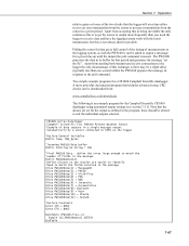
... THE PWS100 SETUP MENU ID {id} SN {sn} (0) message 0 (1) message 1 (2) message 2 (3) set time & date (4) configuration (5) password (6) weather & alarm parameters (7) terminal (any changes will clear current entry and go back to edit or view instrument calibration, type 'confirm' : {input} 0 PWS100 View / Enter calibration disc constants s/n 1234 velocity (m/sec) 5.000 size (mm) 2.386 visibility (mV) 0.318 enter s/n 1234 : {input} enter size constant (mm) 2.386 : {input} enter visibility constant (mV) 0.318 : {input} 1 PWS100 View / Adjust calibration Latest...
... THE PWS100 SETUP MENU ID {id} SN {sn} (0) message 0 (1) message 1 (2) message 2 (3) set time & date (4) configuration (5) password (6) weather & alarm parameters (7) terminal (any changes will clear current entry and go back to edit or view instrument calibration, type 'confirm' : {input} 0 PWS100 View / Enter calibration disc constants s/n 1234 velocity (m/sec) 5.000 size (mm) 2.386 visibility (mV) 0.318 enter s/n 1234 : {input} enter size constant (mm) 2.386 : {input} enter visibility constant (mV) 0.318 : {input} 1 PWS100 View / Adjust calibration Latest...
