
WINDSONIC 2-D Sonic Wind Sensors
Page 6
...angle west of True North (negative) is subtracted from 360 (0) degrees to find True North A-2 A-3. WindSonic1 to 1 23 7-2. Wiring for the conterminous United States (2004) ... WindSonic Orientation A-1 A.1 Determining True North and Sensor Orientation A-1 A.2 Online Magnetic Declination Calculator A-3 B. Magnetic ... of True North (positive) is subtracted from 0 (360) degrees to find True North A-2 A-4. WindSonic1 Output Frequencies 10 7-2. WindSonic mounted on an Edlog table-based datalogger using pn 17837 3 6-1. White dot indicating that Support RS-232 Communications and...
...angle west of True North (negative) is subtracted from 360 (0) degrees to find True North A-2 A-3. WindSonic1 to 1 23 7-2. Wiring for the conterminous United States (2004) ... WindSonic Orientation A-1 A.1 Determining True North and Sensor Orientation A-1 A.2 Online Magnetic Declination Calculator A-3 B. Magnetic ... of True North (positive) is subtracted from 0 (360) degrees to find True North A-2 A-4. WindSonic1 Output Frequencies 10 7-2. WindSonic mounted on an Edlog table-based datalogger using pn 17837 3 6-1. White dot indicating that Support RS-232 Communications and...

WINDSONIC 2-D Sonic Wind Sensors
Page 7
Wiring for CR800 Program Example 21 9-1. Wiring for CR10(X) Program Example 17 7-11. Table of Contents 7-8. WindSonic Data Format Option 15 7-9. Gill WindSonic Diagnostic Codes 27 9-2. Command 16 7-10. Datalogger Operating Systems that Support the SDI-12 "aRo!" Wiring for CR200(X) Program Example 20 7-12. Example Datalogger Program Diagnostic Codes 27 iii
Wiring for CR800 Program Example 21 9-1. Wiring for CR10(X) Program Example 17 7-11. Table of Contents 7-8. WindSonic Data Format Option 15 7-9. Gill WindSonic Diagnostic Codes 27 9-2. Command 16 7-10. Datalogger Operating Systems that Support the SDI-12 "aRo!" Wiring for CR200(X) Program Example 20 7-12. Example Datalogger Program Diagnostic Codes 27 iii

WINDSONIC 2-D Sonic Wind Sensors
Page 9
...read by the CR200(X)-series, CR510, CR10X, CR800, CR850, CR1000, CR3000, or CR5000 dataloggers. WindSonic Two-Dimensional Sonic Anemometer 1. The WindSonic1 outputs an RS-232 signal that an SDI-12 sensor must be able to be periodically replaced- ... Statements • The WindSonic is to traditional mechanical cup and vane or propeller and vane anemometers. See Section 6.4, Campbell Scientific Factory Default Settings for the WindSonic1, and Appendix B for overhead wires before mounting the WindSonic or before raising a tower. • WindSonic1's default settings were changed...
...read by the CR200(X)-series, CR510, CR10X, CR800, CR850, CR1000, CR3000, or CR5000 dataloggers. WindSonic Two-Dimensional Sonic Anemometer 1. The WindSonic1 outputs an RS-232 signal that an SDI-12 sensor must be able to be periodically replaced- ... Statements • The WindSonic is to traditional mechanical cup and vane or propeller and vane anemometers. See Section 6.4, Campbell Scientific Factory Default Settings for the WindSonic1, and Appendix B for overhead wires before mounting the WindSonic or before raising a tower. • WindSonic1's default settings were changed...
WINDSONIC 2-D Sonic Wind Sensors
Page 10
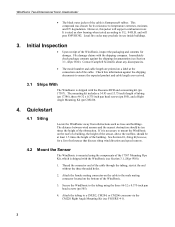
... to the male mating connector located on a label at the connection end of the WindSonic, inspect the packaging and contents for damage. Contact Campbell Scientific about any discrepancies. • The model number and cable length are received. 3.1 Ships With The WindSonic is Santoprene® rubber. See Section 10, Siting References, for its use inside...
... to the male mating connector located on a label at the connection end of the WindSonic, inspect the packaging and contents for damage. Contact Campbell Scientific about any discrepancies. • The model number and cable length are received. 3.1 Ships With The WindSonic is Santoprene® rubber. See Section 10, Siting References, for its use inside...
WINDSONIC 2-D Sonic Wind Sensors
Page 11
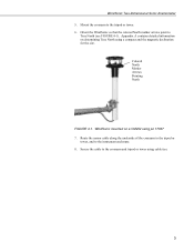
Colored North Marker Arrows Pointing North FIGURE 4-1. WindSonic mounted on determining True North using a compass and the magnetic declination for the site. Mount the crossarm to the crossarm and tripod or tower using ... the tripod or tower. 6. Route the sensor cable along the underside of the crossarm to the tripod or tower, and to True North (see FIGURE 4-1). WindSonic Two-Dimensional Sonic Anemometer 5. Orient the WindSonic so that the colored North marker arrows point to the instrument enclosure. 8.
Colored North Marker Arrows Pointing North FIGURE 4-1. WindSonic mounted on determining True North using a compass and the magnetic declination for the site. Mount the crossarm to the crossarm and tripod or tower using ... the tripod or tower. 6. Route the sensor cable along the underside of the crossarm to the tripod or tower, and to True North (see FIGURE 4-1). WindSonic Two-Dimensional Sonic Anemometer 5. Orient the WindSonic so that the colored North marker arrows point to the instrument enclosure. 8.

WINDSONIC 2-D Sonic Wind Sensors
Page 12
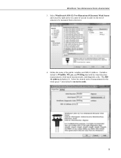
WindSonic Two-Dimensional Sonic Anemometer 4.3 Use Short Cut Program Generator for Windows (SCWin) to Program Datalogger and Generate Wiring Diagram The simplest method for WindSonic1 programming information and additional WindSonic4 programming information. 1. See Section 7, Operation, for programming the datalogger to measure the WindSonic is to use Campbell Scientific's SCWin. Select the datalogger and enter the scan interval. 4 This section provides information about using Short Cut with the WindSonic4. Open Short Cut and click on New Program. 2.
WindSonic Two-Dimensional Sonic Anemometer 4.3 Use Short Cut Program Generator for Windows (SCWin) to Program Datalogger and Generate Wiring Diagram The simplest method for WindSonic1 programming information and additional WindSonic4 programming information. 1. See Section 7, Operation, for programming the datalogger to measure the WindSonic is to use Campbell Scientific's SCWin. Select the datalogger and enter the scan interval. 4 This section provides information about using Short Cut with the WindSonic4. Open Short Cut and click on New Program. 2.
WINDSONIC 2-D Sonic Wind Sensors
Page 13
Define the name of measurement for the wind speed. Variables default to 0. Select the desired units of the public variables and SDI-12 Address. The SDI12 Address defaults to WindDir, WS_ms, and WSDiag that hold the wind direction measurements, wind speed measurements, and diagnostic code. Units default to be measured then select next. 4. WindSonic Two-Dimensional Sonic Anemometer 3. Select WindSonic4 (SDI-12) Two Dimensional Ultrasonic Wind Sensor and select the right arrow (in center of screen) to add it to the list of sensors to meters/seconds. 5
Define the name of measurement for the wind speed. Variables default to 0. Select the desired units of the public variables and SDI-12 Address. The SDI12 Address defaults to WindDir, WS_ms, and WSDiag that hold the wind direction measurements, wind speed measurements, and diagnostic code. Units default to be measured then select next. 4. WindSonic Two-Dimensional Sonic Anemometer 3. Select WindSonic4 (SDI-12) Two Dimensional Ultrasonic Wind Sensor and select the right arrow (in center of screen) to add it to the list of sensors to meters/seconds. 5

WINDSONIC 2-D Sonic Wind Sensors
Page 14
WindSonic Two-Dimensional Sonic Anemometer 5. Select the outputs and then select finish. 6. Wire according to the wiring diagram generated by SCWin Short Cut. 6
WindSonic Two-Dimensional Sonic Anemometer 5. Select the outputs and then select finish. 6. Wire according to the wiring diagram generated by SCWin Short Cut. 6

WINDSONIC 2-D Sonic Wind Sensors
Page 15
... interface standard used during troubleshooting or to a Campbell Scientific datalogger. The CR800-series, CR1000, and CR3000 dataloggers also support the SDI-12 interface. The WindSonic's cable can be interfaced using the control ports. WindSonic Two-Dimensional Sonic Anemometer 5. A serial cable (WINDSONICRCBL-L) is available in two versions. Option 1 WindSonic (WindSonic1) outputs data using the SDI-12 interface...
... interface standard used during troubleshooting or to a Campbell Scientific datalogger. The CR800-series, CR1000, and CR3000 dataloggers also support the SDI-12 interface. The WindSonic's cable can be interfaced using the control ports. WindSonic Two-Dimensional Sonic Anemometer 5. A serial cable (WINDSONICRCBL-L) is available in two versions. Option 1 WindSonic (WindSonic1) outputs data using the SDI-12 interface...

WINDSONIC 2-D Sonic Wind Sensors
Page 16
...: Output Resolution: 0 to 359° (no dead band) ±3° 1° 6.2 Wind Speed Operating Range: Accuracy: Output Resolution: 0 to 1 Hz Current Drain: ~15 mA continuous (WindSonic1) address factory set to 0 Output Variables: wind direction, wind speed, and diagnostic or ux, uy, and diagnostic (WindSonic4 only) Measurement Frequency: 40 Hz block averaged...
...: Output Resolution: 0 to 359° (no dead band) ±3° 1° 6.2 Wind Speed Operating Range: Accuracy: Output Resolution: 0 to 1 Hz Current Drain: ~15 mA continuous (WindSonic1) address factory set to 0 Output Variables: wind direction, wind speed, and diagnostic or ux, uy, and diagnostic (WindSonic4 only) Measurement Frequency: 40 Hz block averaged...

WINDSONIC 2-D Sonic Wind Sensors
Page 17
WindSonic Two-Dimensional Sonic Anemometer 6.4 Campbell Scientific Factory Default Settings for the WindSonic1 The default settings for a WindSonic1 with the newer settings have a white dot next to the connector on the cable; does not apply • Minimum direction velocity (K50) CAUTION WindSonic1s with the newer default settings will not work with a carriage return ...the newer settings. 9 does not apply • Analog wrap around 0 to 30 m s-1 (S4) - Appendix B provides information about updating an older program for the WindSonic1 were changed in February 2013 to 5 Vdc (T1) -
WindSonic Two-Dimensional Sonic Anemometer 6.4 Campbell Scientific Factory Default Settings for the WindSonic1 The default settings for a WindSonic1 with the newer settings have a white dot next to the connector on the cable; does not apply • Minimum direction velocity (K50) CAUTION WindSonic1s with the newer default settings will not work with a carriage return ...the newer settings. 9 does not apply • Analog wrap around 0 to 30 m s-1 (S4) - Appendix B provides information about updating an older program for the WindSonic1 were changed in February 2013 to 5 Vdc (T1) -

WINDSONIC 2-D Sonic Wind Sensors
Page 18
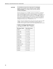
... (see TABLE 7-1) using Gill's PC support software and the RS-232 WindSonic to best mimic a mechanical anemometer, the WindSonic's output frequency must match the datalogger's scan frequency. The factory setting for example, 1 output per second. for the WindSonic1 and WindSonic4 is 1 Hz; TABLE 7-1. WindSonic1 Output Frequencies Output Seconds Frequency (Hz) Per Output (s) 4 0.25 2 0.5 1 1 0.5 2 0.25...
... (see TABLE 7-1) using Gill's PC support software and the RS-232 WindSonic to best mimic a mechanical anemometer, the WindSonic's output frequency must match the datalogger's scan frequency. The factory setting for example, 1 output per second. for the WindSonic1 and WindSonic4 is 1 Hz; TABLE 7-1. WindSonic1 Output Frequencies Output Seconds Frequency (Hz) Per Output (s) 4 0.25 2 0.5 1 1 0.5 2 0.25...
WINDSONIC 2-D Sonic Wind Sensors
Page 19
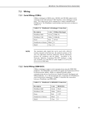
... G NOTE The maximum cable length that can be used between Campbell Scientific dataloggers and SDM peripherals. The WindSonic1 serial interface uses four wires as a single communications (COMn) port. SDM is to limit RS-232 cable lengths to SDM-SIO1 Connections Description WindSonic RxD WindSonic TxD Power Serial/power reference Shield Color Green White Red Black...
... G NOTE The maximum cable length that can be used between Campbell Scientific dataloggers and SDM peripherals. The WindSonic1 serial interface uses four wires as a single communications (COMn) port. SDM is to limit RS-232 cable lengths to SDM-SIO1 Connections Description WindSonic RxD WindSonic TxD Power Serial/power reference Shield Color Green White Red Black...

WINDSONIC 2-D Sonic Wind Sensors
Page 20
... using SDI-12. The datalogger and WindSonic1 each other and will occur if the WindSonic is a three-wire interface used between processor-based sensors and digital recorders (TABLE 7-4). The most current wind data is 0. WindSonic Two-Dimensional Sonic Anemometer 7.2.3 SDI-12 Wiring The WindSonic4 interfaces to a Campbell Scientific datalogger using control ports or the instruction...
... using SDI-12. The datalogger and WindSonic1 each other and will occur if the WindSonic is a three-wire interface used between processor-based sensors and digital recorders (TABLE 7-4). The most current wind data is 0. WindSonic Two-Dimensional Sonic Anemometer 7.2.3 SDI-12 Wiring The WindSonic4 interfaces to a Campbell Scientific datalogger using control ports or the instruction...

WINDSONIC 2-D Sonic Wind Sensors
Page 21
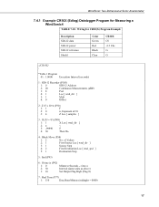
...Datalogger Model CR800-series CR1000 CR3000 Operating System 4.0 or later 13.0 or later 6.0 or later 7.3.1 Example CR1000 Datalogger Program for CR1000 Example Program Description WindSonic RxD WindSonic TxD Power RS-232/Power reference Shield Color Green White Red Black Clear CR1000 COM1 Tx (C1) COM1 Rx (C2) +12 Vdc G G '...diag_2_TOT") Totalize (1,n,IEEE4,diag4) FieldNames ("diag_4_TOT") Totalize (1,n,IEEE4,diag8) FieldNames ("diag_8_TOT") Totalize (1,n,IEEE4,diag9) FieldNames ("diag_9_TOT") Totalize (1,n,IEEE4,diag10) 13 Wiring for Measuring a WindSonic1 using COMn Port TABLE 7-6.
...Datalogger Model CR800-series CR1000 CR3000 Operating System 4.0 or later 13.0 or later 6.0 or later 7.3.1 Example CR1000 Datalogger Program for CR1000 Example Program Description WindSonic RxD WindSonic TxD Power RS-232/Power reference Shield Color Green White Red Black Clear CR1000 COM1 Tx (C1) COM1 Rx (C2) +12 Vdc G G '...diag_2_TOT") Totalize (1,n,IEEE4,diag4) FieldNames ("diag_4_TOT") Totalize (1,n,IEEE4,diag8) FieldNames ("diag_8_TOT") Totalize (1,n,IEEE4,diag9) FieldNames ("diag_9_TOT") Totalize (1,n,IEEE4,diag10) 13 Wiring for Measuring a WindSonic1 using COMn Port TABLE 7-6.

WINDSONIC 2-D Sonic Wind Sensors
Page 22
...WindSonic1 using an SDM-SIO1 TABLE 7-7. wind_direction = windsonic(1) wind_speed = windsonic(2) diag = windsonic(4) checksum_flg = ( (HexToDec (Right (in_bytes_str,2))) EQV (CheckSum (in_bytes_str,9,Len (in_bytes_str)-3)) ) disable_flg = ( NOT (checksum_flg) OR (nmbr_bytes_rtrnd=0) OR (diag0) ) CallTable stats NextScan EndProg 7.3.2 Example CR1000 Datalogger Program for CR1000/SDM-SIO1 Program Example Description WindSonic RxD WindSonic...") Totalize (1,n,IEEE4,diag1) FieldNames ("diag_1_TOT") 14 WindSonic Two-Dimensional Sonic Anemometer FieldNames ("diag_10_TOT") Totalize (1,n,IEEE4...
...WindSonic1 using an SDM-SIO1 TABLE 7-7. wind_direction = windsonic(1) wind_speed = windsonic(2) diag = windsonic(4) checksum_flg = ( (HexToDec (Right (in_bytes_str,2))) EQV (CheckSum (in_bytes_str,9,Len (in_bytes_str)-3)) ) disable_flg = ( NOT (checksum_flg) OR (nmbr_bytes_rtrnd=0) OR (diag0) ) CallTable stats NextScan EndProg 7.3.2 Example CR1000 Datalogger Program for CR1000/SDM-SIO1 Program Example Description WindSonic RxD WindSonic...") Totalize (1,n,IEEE4,diag1) FieldNames ("diag_1_TOT") 14 WindSonic Two-Dimensional Sonic Anemometer FieldNames ("diag_10_TOT") Totalize (1,n,IEEE4...

WINDSONIC 2-D Sonic Wind Sensors
Page 23
... s-1 Compass polar coordinate system unitless m s-1 m s-1 unitless Orthogonal right hand coordinate system 15 wind_direction = windsonic(1) wind_speed = windsonic(2) diag = windsonic(4) checksum_flg = ( (HexToDec (Right (in_bytes_str,2))) EQV (CheckSum (in_bytes_str,9,Len (in_bytes_str)-3)) ) disable_flg = ( ... ) CallTable stats NextScan EndProg 7.4 Datalogger Programming for SDI-12 Output A program for the WindSonic4. TABLE 7-8. WindSonic Two-Dimensional Sonic Anemometer Totalize (1,n,IEEE4,diag2) FieldNames ("diag_2_TOT") Totalize (1,n,IEEE4,diag4) FieldNames ("diag_4_TOT") Totalize ...
... s-1 Compass polar coordinate system unitless m s-1 m s-1 unitless Orthogonal right hand coordinate system 15 wind_direction = windsonic(1) wind_speed = windsonic(2) diag = windsonic(4) checksum_flg = ( (HexToDec (Right (in_bytes_str,2))) EQV (CheckSum (in_bytes_str,9,Len (in_bytes_str)-3)) ) disable_flg = ( ... ) CallTable stats NextScan EndProg 7.4 Datalogger Programming for SDI-12 Output A program for the WindSonic4. TABLE 7-8. WindSonic Two-Dimensional Sonic Anemometer Totalize (1,n,IEEE4,diag2) FieldNames ("diag_2_TOT") Totalize (1,n,IEEE4,diag4) FieldNames ("diag_4_TOT") Totalize ...
WINDSONIC 2-D Sonic Wind Sensors
Page 24
...take slightly longer to transmit the data. The most current wind measurements to 4 WindSonic4s at the Campbell Scientific website in the Support|Downloads section. WindSonic Two-Dimensional Sonic Anemometer CAUTION The WindSonic4 returns three data points; the datalogger program must allocate three...a variable array with the aDo! TABLE 7-9. command, the WindSonic immediately begins transmitting the most current datalogger operating systems are available at 1 Hz. command is used, it takes the WindSonic approximately 190 milliseconds ±10 milliseconds to retrieve the data ...
...take slightly longer to transmit the data. The most current wind measurements to 4 WindSonic4s at the Campbell Scientific website in the Support|Downloads section. WindSonic Two-Dimensional Sonic Anemometer CAUTION The WindSonic4 returns three data points; the datalogger program must allocate three...a variable array with the aDo! TABLE 7-9. command, the WindSonic immediately begins transmitting the most current datalogger operating systems are available at 1 Hz. command is used, it takes the WindSonic approximately 190 milliseconds ±10 milliseconds to retrieve the data ...
WINDSONIC 2-D Sonic Wind Sensors
Page 25
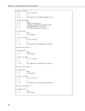
of 10 3: 4 Z Loc [ samples ] 3: If (XF) (P89) 1: 1 X Loc [ wnd_dir ] 2: 4 < 3: -99990 F 4: 30 Then Do 4: Block Move (P54) 1: 2 No. Wiring for Measuring a WindSonic4 TABLE 7-10. WindSonic Two-Dimensional Sonic Anemometer 7.4.1 Example CR10X (Edlog) Datalogger Program for CR10(X) Program Example Description SDI-12 data SDI-12 power SDI-12 reference Shield Color ...
of 10 3: 4 Z Loc [ samples ] 3: If (XF) (P89) 1: 1 X Loc [ wnd_dir ] 2: 4 < 3: -99990 F 4: 30 Then Do 4: Block Move (P54) 1: 2 No. Wiring for Measuring a WindSonic4 TABLE 7-10. WindSonic Two-Dimensional Sonic Anemometer 7.4.1 Example CR10X (Edlog) Datalogger Program for CR10(X) Program Example Description SDI-12 data SDI-12 power SDI-12 reference Shield Color ...
WINDSONIC 2-D Sonic Wind Sensors
Page 26
WindSonic Two-Dimensional Sonic Anemometer 8: If (XF) (P89) 1: 3 X Loc [ ws_diag ] 2: 2 3: 0 F 4: 19 Set Intermed. Proc. Proc. Proc. Disable Flag Low (Flag 9) ;Report the total of diag = 4. ; 16: ...
WindSonic Two-Dimensional Sonic Anemometer 8: If (XF) (P89) 1: 3 X Loc [ ws_diag ] 2: 2 3: 0 F 4: 19 Set Intermed. Proc. Proc. Proc. Disable Flag Low (Flag 9) ;Report the total of diag = 4. ; 16: ...
