

LGJ Manual
Page 1
OWNER'S MANUAL MODELS: LGJ & MGJ INDUSTRIAL DUTY DOOR OPERATOR 2 YEAR WARRANTY Serial # (located on electrical box cover) Installation Date Wiring Type NOT FOR RESIDENTIAL USE 41B6 LISTED DOOR OPERATOR
OWNER'S MANUAL MODELS: LGJ & MGJ INDUSTRIAL DUTY DOOR OPERATOR 2 YEAR WARRANTY Serial # (located on electrical box cover) Installation Date Wiring Type NOT FOR RESIDENTIAL USE 41B6 LISTED DOOR OPERATOR

LGJ Manual
Page 2
SAFETY DISCONNECT Floor level disconnect for optional control settings and operating modes. 380V, 50Hz, 3Ph 460V, 60Hz, 3Ph LGJ: 115V, 60Hz, 1Ph LIMIT ADJUST Linear driven, fully adjustable screw type cams. Adjustable to the bottom edge of door A REVERSING EDGE IS STRONGLY RECOMMENDED FOR ALL COMMERCIAL OPERATOR INSTALLATIONS. OPEN/CLOSE/STOP SPEED MGJ: 1050 RPM LGJ: 1725 RPM VOLTAGE MGJ: 115, 60HZ, 1Ph WIRING TYPE: MGJ: B2-C2 (Factory Shipped) LGJ: G2 (Factory Shipped) 230V...
SAFETY DISCONNECT Floor level disconnect for optional control settings and operating modes. 380V, 50Hz, 3Ph 460V, 60Hz, 3Ph LGJ: 115V, 60Hz, 1Ph LIMIT ADJUST Linear driven, fully adjustable screw type cams. Adjustable to the bottom edge of door A REVERSING EDGE IS STRONGLY RECOMMENDED FOR ALL COMMERCIAL OPERATOR INSTALLATIONS. OPEN/CLOSE/STOP SPEED MGJ: 1050 RPM LGJ: 1725 RPM VOLTAGE MGJ: 115, 60HZ, 1Ph WIRING TYPE: MGJ: B2-C2 (Factory Shipped) LGJ: G2 (Factory Shipped) 230V...

LGJ Manual
Page 3
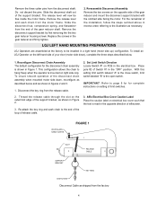
... ADJUST DOOR CAUTION SPRINGS OR HARDWARE. b) Provide a level base. See Figure 1. 22.-715/4fo" r MGJ, butt together for LGJ FIGURE 1 OPERATOR PREPARATION Model LGJ: Shipped from the factory for Left hand mounting. Remove the two E Rings securing the sprocket on page 4 for right hand mounting, refer to the door shaft. Shaft Support Bracket with the drive shaft parallel to preparation instructions on the gear reducer shaft. Model MGJ: Shipped from the limit chain, remove the chain and set...
... ADJUST DOOR CAUTION SPRINGS OR HARDWARE. b) Provide a level base. See Figure 1. 22.-715/4fo" r MGJ, butt together for LGJ FIGURE 1 OPERATOR PREPARATION Model LGJ: Shipped from the factory for Left hand mounting. Remove the two E Rings securing the sprocket on page 4 for right hand mounting, refer to the door shaft. Shaft Support Bracket with the drive shaft parallel to preparation instructions on the gear reducer shaft. Model MGJ: Shipped from the limit chain, remove the chain and set...
LGJ Manual
Page 4
... of Switch #1 in the electrical box. Slide the disconnect hub, compression spring, and flatwasher from the motor frame. Place pole #2 of the gear reducer shaft. With this setting limit switch labeled "A" is the close switch, limit switch labeled "B" is mounted on right side only. Re-attach the key ring and sash chain to page 9 for for the disconnect chain assembly is read in figures 2 and 3. 1. LGJ LEFT HAND MOUNTING PREPARATIONS LGJ Operators are assembled...
... of Switch #1 in the electrical box. Slide the disconnect hub, compression spring, and flatwasher from the motor frame. Place pole #2 of the gear reducer shaft. With this setting limit switch labeled "A" is the close switch, limit switch labeled "B" is mounted on right side only. Re-attach the key ring and sash chain to page 9 for for the disconnect chain assembly is read in figures 2 and 3. 1. LGJ LEFT HAND MOUNTING PREPARATIONS LGJ Operators are assembled...
LGJ Manual
Page 5
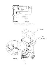
SUPPORT BRACKET RELEASE CABLE SLOT HOUR GLASS CABLE SLEEVE KEY RING FIGURE 2 SASH CHAIN Disconnect Cable Re-routed for Left Hand Mounting LABEL SILK SCREEN FIGURE 3 5
SUPPORT BRACKET RELEASE CABLE SLOT HOUR GLASS CABLE SLEEVE KEY RING FIGURE 2 SASH CHAIN Disconnect Cable Re-routed for Left Hand Mounting LABEL SILK SCREEN FIGURE 3 5

LGJ Manual
Page 6
... key at this time. 2. Raise operator to the illustration and instructions below the door shaft. The operator may be fastened securely and with the drive shaft parallel to the shaft. Refer to approximate mounting position and position chain over operator sprocket. 4. OPTIONAL (LGJ) Mounting Bracket OPTIONAL (MGJ) Mounting Bracket P/N 10-9098 Typical Right Hand Wall Mounted Operator FIGURE 3 IMPORTANT: The shelf or bracket must provide adequate support, prevent play between the door shaft and operator drive shaft is working smoothly. Place door sprocket...
... key at this time. 2. Raise operator to the illustration and instructions below the door shaft. The operator may be fastened securely and with the drive shaft parallel to the shaft. Refer to approximate mounting position and position chain over operator sprocket. 4. OPTIONAL (LGJ) Mounting Bracket OPTIONAL (MGJ) Mounting Bracket P/N 10-9098 Typical Right Hand Wall Mounted Operator FIGURE 3 IMPORTANT: The shelf or bracket must provide adequate support, prevent play between the door shaft and operator drive shaft is working smoothly. Place door sprocket...
LGJ Manual
Page 7
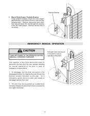
... EMERGENCY MANUAL OPERATION CAUTION TURN OFF POWER TO THE OPERATOR BEFORE MANUALLY OPERATING YOUR DOOR. Release the disconnect chain to disconnect the door from door. 2. Or if emergency egress device is used, pull handle to disengage operator from the door operator allowing for manual operation of the door. The door may now be pushed up or pulled down manually. Remove disconnect sash chain from bag and place the end through the keyhole bracket mounted on the wall. Mount Chain Keeper / Keyhole Bracket Using...
... EMERGENCY MANUAL OPERATION CAUTION TURN OFF POWER TO THE OPERATOR BEFORE MANUALLY OPERATING YOUR DOOR. Release the disconnect chain to disconnect the door from door. 2. Or if emergency egress device is used, pull handle to disengage operator from the door operator allowing for manual operation of the door. The door may now be pushed up or pulled down manually. Remove disconnect sash chain from bag and place the end through the keyhole bracket mounted on the wall. Mount Chain Keeper / Keyhole Bracket Using...

LGJ Manual
Page 8
... not pre-installed by either coiled cord or take-up the door opening . 4. b) Electrician must hardwire the junction box to spin freely. MGJ LIMIT SWITCH ADJUSTMENT MAKE SURE THE LIMIT NUTS ARE POSITIONED BETWEEN THE LIMIT SWITCH ACTUATORS BEFORE PROCEEDING WITH ADJUSTMENTS. 1. If other problems persist, call our toll-free number for close limit nut so that door will stop in accordance with local codes. To increase door travel , spin limit nut...
... not pre-installed by either coiled cord or take-up the door opening . 4. b) Electrician must hardwire the junction box to spin freely. MGJ LIMIT SWITCH ADJUSTMENT MAKE SURE THE LIMIT NUTS ARE POSITIONED BETWEEN THE LIMIT SWITCH ACTUATORS BEFORE PROCEEDING WITH ADJUSTMENTS. 1. If other problems persist, call our toll-free number for close limit nut so that door will stop in accordance with local codes. To increase door travel , spin limit nut...

LGJ Manual
Page 9
... Limit Switch -B(Bottom Switch) If your operator is the CLOSE limit. Limit Switch -B- NOTE: See Mounting Options on circuit board. Test Limit Travel Manually move the door to a half-open position. (see page 17, Manual Operation) WARNING C. See Step A for correct setting. pole 2 position is mounted Motor Side Down: Set dip switch SW1 - If your OPEN and CLOSE limit switches. Limit switch -B- Manually raise the door to a nearly open position to avoid damage due to incorrect (dip switch setting) limit travel is the CLOSE limit. LGJ LIMIT SWITCH ADJUSTMENT IMPORTANT...
... Limit Switch -B(Bottom Switch) If your operator is the CLOSE limit. Limit Switch -B- NOTE: See Mounting Options on circuit board. Test Limit Travel Manually move the door to a half-open position. (see page 17, Manual Operation) WARNING C. See Step A for correct setting. pole 2 position is mounted Motor Side Down: Set dip switch SW1 - If your OPEN and CLOSE limit switches. Limit switch -B- Manually raise the door to a nearly open position to avoid damage due to incorrect (dip switch setting) limit travel is the CLOSE limit. LGJ LIMIT SWITCH ADJUSTMENT IMPORTANT...
LGJ Manual
Page 10
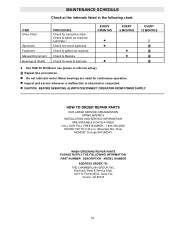
... motor. CAUTION: BEFORE SERVICING, ALWAYS DISCONNECT OPERATOR FROM POWER SUPPLY. Electronic Parts & Service Dept. 2301 N. Check & adjust as required Check & Operate Check for wear & lubricate EVERY 3 MONTHS EVERY 6 MONTHS EVERY 12 MONTHS Use SAE 30 Oil (Never use grease or silicone spray). Time) MONDAY Through SATURDAY WHEN ORDERING REPAIR PARTS PLEASE SUPPLY THE FOLLOWING INFORMATION: PART NUMBER DESCRIPTION MODEL NUMBER ADDRESS ORDER TO: THE CHAMBERLAIN GROUP, INC. Inspect and service...
... motor. CAUTION: BEFORE SERVICING, ALWAYS DISCONNECT OPERATOR FROM POWER SUPPLY. Electronic Parts & Service Dept. 2301 N. Check & adjust as required Check & Operate Check for wear & lubricate EVERY 3 MONTHS EVERY 6 MONTHS EVERY 12 MONTHS Use SAE 30 Oil (Never use grease or silicone spray). Time) MONDAY Through SATURDAY WHEN ORDERING REPAIR PARTS PLEASE SUPPLY THE FOLLOWING INFORMATION: PART NUMBER DESCRIPTION MODEL NUMBER ADDRESS ORDER TO: THE CHAMBERLAIN GROUP, INC. Inspect and service...
LGJ Manual
Page 11
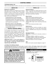
.... Operational Features: REVERSE (if closing Door Lock Sensing Circuit. STOP after maximum run time is provided. Mount the control station near the door. The operator will require constant pressure on button to close (B2 wiring) Move red jumper wire from the factory with jumper set for all control pneumatic safety (N.C.) to STOP while closing Safety Device to close control jumper setting below the push button station. CLOSE control requiring only momentary contact. OPEN/CLOSE single control requiring momentary contact.. Refer only to the replacement wiring diagram for...
.... Operational Features: REVERSE (if closing Door Lock Sensing Circuit. STOP after maximum run time is provided. Mount the control station near the door. The operator will require constant pressure on button to close (B2 wiring) Move red jumper wire from the factory with jumper set for all control pneumatic safety (N.C.) to STOP while closing Safety Device to close control jumper setting below the push button station. CLOSE control requiring only momentary contact. OPEN/CLOSE single control requiring momentary contact.. Refer only to the replacement wiring diagram for...
LGJ Manual
Page 12
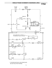
... SWITCH TO OPEN & CLOSE 7 Y R2 Y AUX. C OPEN L/S CLOSE P P CL 2 * TO REVERSE MOTOR ROTATION INTERCHANGE RED AND YELLOW MOTOR WIRES. 12 W CLOSE L/S P W N.C. W RES. SEC. OR W 11 N.C. Y (HOT) L2 BK OPEN-A Y CAPACITOR R MOTOR * BK O/L L1 (N) BR R BK 3 STOP 4 Y MOVE JUMPER WIRE TO TERMINAL #2 FOR MOMENTARY CONTACT ON CLOSE WIRE NUT W PR1. 10VA. R BL 12 CLOSE-A BL R BR R1 BR OPEN-B C N.O. EDGE 10 CLOSE L/S GY GY OR GY OR OP OPEN L.S. 1754 SINGLE PHASE SCHEMATIC DIAGRAM for...
... SWITCH TO OPEN & CLOSE 7 Y R2 Y AUX. C OPEN L/S CLOSE P P CL 2 * TO REVERSE MOTOR ROTATION INTERCHANGE RED AND YELLOW MOTOR WIRES. 12 W CLOSE L/S P W N.C. W RES. SEC. OR W 11 N.C. Y (HOT) L2 BK OPEN-A Y CAPACITOR R MOTOR * BK O/L L1 (N) BR R BK 3 STOP 4 Y MOVE JUMPER WIRE TO TERMINAL #2 FOR MOMENTARY CONTACT ON CLOSE WIRE NUT W PR1. 10VA. R BL 12 CLOSE-A BL R BR R1 BR OPEN-B C N.O. EDGE 10 CLOSE L/S GY GY OR GY OR OP OPEN L.S. 1754 SINGLE PHASE SCHEMATIC DIAGRAM for...
LGJ Manual
Page 13
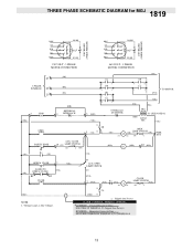
...) 2 (PUR) 14 (PUR) R1 (PUR) A2 CLOSE LIMIT SWITCH CL (PUR) A1 NC (PUR) C CL (RED) 13 * - Shipped from Factory) B2 WIRING - Momentary Contact to Close RED WIRE ON TERMINAL #2 (Shipped from Factory CLOSE CONTROL WIRING OPTIONS *C2 WIRING - CLOSE 10 (GY) LIMIT SWITCH NC C (GY) (RED) R1 (RED) R3 (RED) (OR) OPEN & CLOSE 7 RADIO TO OPEN & CLOSE (OR) (YEL) R1 R2 CLOSE (RED) NOTE: 1. 1819 THREE PHASE SCHEMATIC DIAGRAM for MGJ 230V BRAKE (WHEN PRESENT) 230V...
...) 2 (PUR) 14 (PUR) R1 (PUR) A2 CLOSE LIMIT SWITCH CL (PUR) A1 NC (PUR) C CL (RED) 13 * - Shipped from Factory) B2 WIRING - Momentary Contact to Close RED WIRE ON TERMINAL #2 (Shipped from Factory CLOSE CONTROL WIRING OPTIONS *C2 WIRING - CLOSE 10 (GY) LIMIT SWITCH NC C (GY) (RED) R1 (RED) R3 (RED) (OR) OPEN & CLOSE 7 RADIO TO OPEN & CLOSE (OR) (YEL) R1 R2 CLOSE (RED) NOTE: 1. 1819 THREE PHASE SCHEMATIC DIAGRAM for MGJ 230V BRAKE (WHEN PRESENT) 230V...

LGJ Manual
Page 15
....6 sec SETTING 1 2 3 4 O O O F F O O F O F O F F F O F O O F F F O F F O F F F F F F F TIME = 72 sec = 88 sec = 107 sec = 126sec = 148 sec = 172 sec = 198 sec = 224 sec LGJ CONTROL CONNECTION DIAGRAM 41B6 LISTED DOOR OPERATOR NUMBERED BOXES CORRESPOND WITH TERMINALS ON J1 CONNECTOR STRIP If Neccessary, Remove The Connector Block From The Board To Secure Each Wire Connection Connect field wires to keep door moving . 7 - See control options below for each terminal number. 11 OR 7 9 OR OR 4 8 5 3 OPEN CLOSE STOP STANDARD 3 BUTTON CONTROL 10 5 SENSING...
....6 sec SETTING 1 2 3 4 O O O F F O O F O F O F F F O F O O F F F O F F O F F F F F F F TIME = 72 sec = 88 sec = 107 sec = 126sec = 148 sec = 172 sec = 198 sec = 224 sec LGJ CONTROL CONNECTION DIAGRAM 41B6 LISTED DOOR OPERATOR NUMBERED BOXES CORRESPOND WITH TERMINALS ON J1 CONNECTOR STRIP If Neccessary, Remove The Connector Block From The Board To Secure Each Wire Connection Connect field wires to keep door moving . 7 - See control options below for each terminal number. 11 OR 7 9 OR OR 4 8 5 3 OPEN CLOSE STOP STANDARD 3 BUTTON CONTROL 10 5 SENSING...
LGJ Manual
Page 16
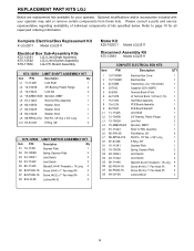
... Roll Pin, 1/8" Dia. Complete Electrical Box Replacement Kit K-LGJ2511 Model LGJ2511 Electrical Box Sub-Assembly Kits K72-12581 LGJ Limit Shaft Assembly K75-12582 LGJ Limit Switch Assembly K79-11384 LGJ PC Board Assembly K72-12581 LIMIT SHAFT ASSEMBLY KIT Item P/N Description Qty L1 11-11425 Limit Shaft 1 L2 12-10458 3/8" Bearing, Plastic Flange 2 L3 13-10024 Limit Nut 2 L4 15-48B07AXX Sprocket, 48B07 1 L5 81-11443 Rotor for all repair part ordering information. x 3/4" Long 1 L10 87-E-038 E Ring, 3/8" 3 K75-12582 LIMIT SWITCH ASSEMBLY KIT Item...
... Roll Pin, 1/8" Dia. Complete Electrical Box Replacement Kit K-LGJ2511 Model LGJ2511 Electrical Box Sub-Assembly Kits K72-12581 LGJ Limit Shaft Assembly K75-12582 LGJ Limit Switch Assembly K79-11384 LGJ PC Board Assembly K72-12581 LIMIT SHAFT ASSEMBLY KIT Item P/N Description Qty L1 11-11425 Limit Shaft 1 L2 12-10458 3/8" Bearing, Plastic Flange 2 L3 13-10024 Limit Nut 2 L4 15-48B07AXX Sprocket, 48B07 1 L5 81-11443 Rotor for all repair part ordering information. x 3/4" Long 1 L10 87-E-038 E Ring, 3/8" 3 K75-12582 LIMIT SWITCH ASSEMBLY KIT Item...
LGJ Manual
Page 17
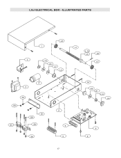
LGJ ELECTRICAL BOX - ILLUSTRATED PARTS L3 1 L1 L10 L5 L9 7 L10 L3 L8 L7 L2 WARNING 4 3 S2 WARNING S8 S1 S6 S3 S4 S5 2 6 5 S7 L2 L6 L10 L4 8 9 17
LGJ ELECTRICAL BOX - ILLUSTRATED PARTS L3 1 L1 L10 L5 L9 7 L10 L3 L8 L7 L2 WARNING 4 3 S2 WARNING S8 S1 S6 S3 S4 S5 2 6 5 S7 L2 L6 L10 L4 8 9 17

LGJ Manual
Page 18
... parts lists below for replacement kits available for all repair part ordering information. x 1" Long 1 D13 87-E-075 E Ring 3/4" 1 18 REPLACEMENT PART LISTS - Please consult a parts and service representative regarding availability of each kit may be available. K75-12583 DISCONNECT ASSEMBLY KIT INDIVIDUAL PARTS ITEM PART # DESCRIPTION QTY ITEM PART # DESCRIPTION QTY D1 10-11023 Bevel Gear Yoke 1 1 10-11397 Support Bracket 1 D2 10-11393 Disconnect 1 2 10-11389-1 Mounting Bracket (LH) 1 D3 10-11394 Release...
... parts lists below for replacement kits available for all repair part ordering information. x 1" Long 1 D13 87-E-075 E Ring 3/4" 1 18 REPLACEMENT PART LISTS - Please consult a parts and service representative regarding availability of each kit may be available. K75-12583 DISCONNECT ASSEMBLY KIT INDIVIDUAL PARTS ITEM PART # DESCRIPTION QTY ITEM PART # DESCRIPTION QTY D1 10-11023 Bevel Gear Yoke 1 1 10-11397 Support Bracket 1 D2 10-11393 Disconnect 1 2 10-11389-1 Mounting Bracket (LH) 1 D3 10-11394 Release...

LGJ Manual
Page 20
... 13-10024 Limit Nut 2 L4 15-48B07AXX Sprocket, 48B07 1 L5 80-10026 Washer, Shim 3/8" I .D. REPLACEMENT PART KITS MGJ Below are replacement kits available for all repair part ordering information. For replacement of electrical box, motor or brake components be sure to ensure proper voltage requirements. Optional modifications and/or accessories included with your unit to kit number below to match model number of kits specified below. Please consult a parts and service representative...
... 13-10024 Limit Nut 2 L4 15-48B07AXX Sprocket, 48B07 1 L5 80-10026 Washer, Shim 3/8" I .D. REPLACEMENT PART KITS MGJ Below are replacement kits available for all repair part ordering information. For replacement of electrical box, motor or brake components be sure to ensure proper voltage requirements. Optional modifications and/or accessories included with your unit to kit number below to match model number of kits specified below. Please consult a parts and service representative...

LGJ Manual
Page 22
... operator. K75-12567 DISCONNECT ASSEMBLY KIT INDIVIDUAL PARTS ITEM PART # DESCRIPTION QTY ITEM PART # DESCRIPTION QTY D1 07-11418 Disconnect Hub 1 1 10-11357 Brake Mounting Plate 1 D2 10-11023 Bevel Gear Yoke 1 2 10-11359 Front Bracket 1 D3 10-11358 Disconnect Support Bracket 1 3 32-11414 Gear Reducer, 45:1 1 D4 10-11394 Release Lever 1 4 See Page 20 Electrical Box 1 D5 11-11361 Disconnect Shaft MGJ 1 5 See Page 20 Motor...
... operator. K75-12567 DISCONNECT ASSEMBLY KIT INDIVIDUAL PARTS ITEM PART # DESCRIPTION QTY ITEM PART # DESCRIPTION QTY D1 07-11418 Disconnect Hub 1 1 10-11357 Brake Mounting Plate 1 D2 10-11023 Bevel Gear Yoke 1 2 10-11359 Front Bracket 1 D3 10-11358 Disconnect Support Bracket 1 3 32-11414 Gear Reducer, 45:1 1 D4 10-11394 Release Lever 1 4 See Page 20 Electrical Box 1 D5 11-11361 Disconnect Shaft MGJ 1 5 See Page 20 Motor...

LGJ Manual
Page 24
... Chamberlain Group, Inc. before door closes. 11 12 13 14 Auxiliary Terminal Block Remove Jumper When Interlock is not used, a jumper must be connected for operation. RADIO TO OPEN ONLY EXTERNAL INTERLOCK Warning Light will activate 15 sec. USE 16 GAUGE OR HEAVIER WIRE 3) Auxiliary control equipment may be placed between termianls 3 and 4. MGJ CONTROL CONNECTION DIAGRAM IMPORTANT NOTES: (Refer to page 15 for model LGJ control connections) 1) The 3-Button Control Station...
... Chamberlain Group, Inc. before door closes. 11 12 13 14 Auxiliary Terminal Block Remove Jumper When Interlock is not used, a jumper must be connected for operation. RADIO TO OPEN ONLY EXTERNAL INTERLOCK Warning Light will activate 15 sec. USE 16 GAUGE OR HEAVIER WIRE 3) Auxiliary control equipment may be placed between termianls 3 and 4. MGJ CONTROL CONNECTION DIAGRAM IMPORTANT NOTES: (Refer to page 15 for model LGJ control connections) 1) The 3-Button Control Station...


