

LGJ Manual
Page 2
OPEN/CLOSE/STOP SPEED MGJ: 1050 RPM LGJ: 1725 RPM VOLTAGE MGJ: 115, 60HZ, 1Ph WIRING TYPE: MGJ: B2-C2 (Factory Shipped) LGJ: G2 (Factory Shipped) 230V, 50 or 60Hz, 3Ph 230V, 60Hz, 1Ph See pages 13 and 14 for emergency manual door operation. REVERSING EDGE...nameplate MECHANICAL DRIVE REDUCTION 40:1 Reduction (Heavy duty wormgear-in-oil-bath speed reducer) OUTPUT SPROCKET:...........Size #41 DOOR SPEED: ..........MGJ: 1Ph, 23RPM 3Ph, 39RPM LGJ: .1Ph, 43RPM BEARINGS Heavy duty wormgear-in-oil-bath speed reducer. SPECIFICATIONS MOTOR TYPE Intermittent Duty ELECTRICAL TRANSFORMER...
OPEN/CLOSE/STOP SPEED MGJ: 1050 RPM LGJ: 1725 RPM VOLTAGE MGJ: 115, 60HZ, 1Ph WIRING TYPE: MGJ: B2-C2 (Factory Shipped) LGJ: G2 (Factory Shipped) 230V, 50 or 60Hz, 3Ph 230V, 60Hz, 1Ph See pages 13 and 14 for emergency manual door operation. REVERSING EDGE...nameplate MECHANICAL DRIVE REDUCTION 40:1 Reduction (Heavy duty wormgear-in-oil-bath speed reducer) OUTPUT SPROCKET:...........Size #41 DOOR SPEED: ..........MGJ: 1Ph, 23RPM 3Ph, 39RPM LGJ: .1Ph, 43RPM BEARINGS Heavy duty wormgear-in-oil-bath speed reducer. SPECIFICATIONS MOTOR TYPE Intermittent Duty ELECTRICAL TRANSFORMER...

LGJ Manual
Page 3
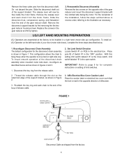
...E Rings securing the sprocket on page 4. CALL A PROFESSIONAL DOOR SERVICEMAN TO MOVE OR ADJUST DOOR CAUTION SPRINGS OR HARDWARE. See Figure 1. 22.-715/4fo" r MGJ, butt together for LGJ FIGURE 1 OPERATOR PREPARATION Model LGJ: Shipped from the factory for right hand mounting, refer to...BRACKET YOKE SHAFT DISC LEVER 3 IMPORTANT SAFETY NOTES CAUTION WARWNAINRGNING W TO AVOID DAMAGE TO DOOR AND OPERATOR, MAKE ALL DOOR LOCKS INOPERATIVE. SECURE LOCK(S) IN "OPEN" POSITION. IF THE DOOR LOCK NEEDS TO REMAIN FUNCTIONAL, INSTALL AN INTERLOCK SWITCH. SITE PREPARATIONS It is imperative ...
...E Rings securing the sprocket on page 4. CALL A PROFESSIONAL DOOR SERVICEMAN TO MOVE OR ADJUST DOOR CAUTION SPRINGS OR HARDWARE. See Figure 1. 22.-715/4fo" r MGJ, butt together for LGJ FIGURE 1 OPERATOR PREPARATION Model LGJ: Shipped from the factory for right hand mounting, refer to...BRACKET YOKE SHAFT DISC LEVER 3 IMPORTANT SAFETY NOTES CAUTION WARWNAINRGNING W TO AVOID DAMAGE TO DOOR AND OPERATOR, MAKE ALL DOOR LOCKS INOPERATIVE. SECURE LOCK(S) IN "OPEN" POSITION. IF THE DOOR LOCK NEEDS TO REMAIN FUNCTIONAL, INSTALL AN INTERLOCK SWITCH. SITE PREPARATIONS It is imperative ...
LGJ Manual
Page 4
.... The release lever will now be installed in the opposite direction of silkscreen. LGJ LEFT HAND MOUNTING PREPARATIONS LGJ Operators are assembled at the factory to hang freely when the operator is read ... key ring and sash chain to page 9 for for the disconnect chain assembly is the open switch. Remove the disconnect support bracket by first removing the the two gear reducer housing screws... Disconnect Chain Assembly The default configuration for complete instructions on the left hand side of your door (motor side down , reconfigure as shown in figures 2 and 3. 1. Set Limit Switch...
.... The release lever will now be installed in the opposite direction of silkscreen. LGJ LEFT HAND MOUNTING PREPARATIONS LGJ Operators are assembled at the factory to hang freely when the operator is read ... key ring and sash chain to page 9 for for the disconnect chain assembly is the open switch. Remove the disconnect support bracket by first removing the the two gear reducer housing screws... Disconnect Chain Assembly The default configuration for complete instructions on the left hand side of your door (motor side down , reconfigure as shown in figures 2 and 3. 1. Set Limit Switch...

LGJ Manual
Page 8
... cord to junction box (not supplied) fastened to the wall approximately halfway up the door opening . 4. COIL CORD: Connect operator end of sensing edges with an isolated normally open (N.O.) output are compatible with your operator. After adjustment, release plate and ensure it... connections to purchase one, contact the supplier of door opening . Important Notes: a) Proceed with the edge. b) Electrician must hardwire the junction box to spin freely. To increase door travel , spin limit nut toward actuator. To decrease door travel , spin nut away from actuator. Repeat ...
... cord to junction box (not supplied) fastened to the wall approximately halfway up the door opening . 4. COIL CORD: Connect operator end of sensing edges with an isolated normally open (N.O.) output are compatible with your operator. After adjustment, release plate and ensure it... connections to purchase one, contact the supplier of door opening . Important Notes: a) Proceed with the edge. b) Electrician must hardwire the junction box to spin freely. To increase door travel , spin limit nut toward actuator. To decrease door travel , spin nut away from actuator. Repeat ...

LGJ Manual
Page 9
...power to the operator. is determined by SW1 - Limit switch -B- limit switches. B. E. In either instance, the limit nuts will cause the door to OPEN when the limit nuts are traveling in the direction of the CLOSE limit switch or vice versa. F. pole 2 position is the close limit. pole...activates a switch(es). pole 2 position is the OPEN limit. is mounted Motor Side Up: Set dip switch SW1 - Limit Switch -B- Depress the limit nut retaining bracket away from the slots in the slots of both the door and operator. LGJ LIMIT SWITCH ADJUSTMENT IMPORTANT NOTE: To avoid danger ...
...power to the operator. is determined by SW1 - Limit switch -B- limit switches. B. E. In either instance, the limit nuts will cause the door to OPEN when the limit nuts are traveling in the direction of the CLOSE limit switch or vice versa. F. pole 2 position is the close limit. pole...activates a switch(es). pole 2 position is the OPEN limit. is mounted Motor Side Up: Set dip switch SW1 - Limit Switch -B- Depress the limit nut retaining bracket away from the slots in the slots of both the door and operator. LGJ LIMIT SWITCH ADJUSTMENT IMPORTANT NOTE: To avoid danger ...
LGJ Manual
Page 11
... NOTICE IMPORTANT: Mount WARNING NOTICE beside or below to LGJ control connection diagrams on terminal #2 in either direction for all control pneumatic safety (N.C.) to STOP while closing Safety Device to the wiring diagram(s) indicated in the close the door. Constant pressure on OPEN. OPEN/CLOSE single control requiring momentary contact.. Mount the control station...
... NOTICE IMPORTANT: Mount WARNING NOTICE beside or below to LGJ control connection diagrams on terminal #2 in either direction for all control pneumatic safety (N.C.) to STOP while closing Safety Device to the wiring diagram(s) indicated in the close the door. Constant pressure on OPEN. OPEN/CLOSE single control requiring momentary contact.. Mount the control station...

LGJ Manual
Page 15
...O O F F O O F O F O F F F O F O O F F F O F F O F F F F F F F TIME = 72 sec = 88 sec = 107 sec = 126sec = 148 sec = 172 sec = 198 sec = 224 sec LGJ CONTROL CONNECTION DIAGRAM 41B6 LISTED DOOR OPERATOR NUMBERED BOXES CORRESPOND WITH TERMINALS ON J1 CONNECTOR STRIP If Neccessary, Remove The Connector Block From The Board To Secure Each Wire... Connection Connect field wires to keep door moving . 9 - Open control will only require momentary contact and will set or reset timer to keep door moving . 7 - DO NOT add unless using an entrapment Protection device...
...O O F F O O F O F O F F F O F O O F F F O F F O F F F F F F F TIME = 72 sec = 88 sec = 107 sec = 126sec = 148 sec = 172 sec = 198 sec = 224 sec LGJ CONTROL CONNECTION DIAGRAM 41B6 LISTED DOOR OPERATOR NUMBERED BOXES CORRESPOND WITH TERMINALS ON J1 CONNECTOR STRIP If Neccessary, Remove The Connector Block From The Board To Secure Each Wire... Connection Connect field wires to keep door moving . 9 - Open control will only require momentary contact and will set or reset timer to keep door moving . 7 - DO NOT add unless using an entrapment Protection device...

LGJ Manual
Page 24
...OR STOP RESIDENTIAL RADIO CONTROLS 3 10 *OPEN TIMER TO CLOSE R1 R2 R3 EXTERNAL TERMINAL BLOCK Sensing Device RADIO CONTROL ALL CONTROL WIRING TYPES TIMER TO CLOSE w/ WARNING LIGHT ALL CONTROL WIRING TYPES * T1 WIRING - All rights Reserved before door closes. 11 12 13 14 Auxiliary Terminal...Auxiliary control equipment may be placed between termianls 3 and 4. MGJ CONTROL CONNECTION DIAGRAM IMPORTANT NOTES: (Refer to page 15 for model LGJ control connections) 1) The 3-Button Control Station provided must be any normally open two wire device such as FOR ALL CONTROL CIRCUIT WIRING.
...OR STOP RESIDENTIAL RADIO CONTROLS 3 10 *OPEN TIMER TO CLOSE R1 R2 R3 EXTERNAL TERMINAL BLOCK Sensing Device RADIO CONTROL ALL CONTROL WIRING TYPES TIMER TO CLOSE w/ WARNING LIGHT ALL CONTROL WIRING TYPES * T1 WIRING - All rights Reserved before door closes. 11 12 13 14 Auxiliary Terminal...Auxiliary control equipment may be placed between termianls 3 and 4. MGJ CONTROL CONNECTION DIAGRAM IMPORTANT NOTES: (Refer to page 15 for model LGJ control connections) 1) The 3-Button Control Station provided must be any normally open two wire device such as FOR ALL CONTROL CIRCUIT WIRING.


