

LGJ Manual
Page 1
OWNER'S MANUAL MODELS: LGJ & MGJ INDUSTRIAL DUTY DOOR OPERATOR 2 YEAR WARRANTY Serial # (located on electrical box cover) Installation Date Wiring Type NOT FOR RESIDENTIAL USE 41B6 LISTED DOOR OPERATOR
OWNER'S MANUAL MODELS: LGJ & MGJ INDUSTRIAL DUTY DOOR OPERATOR 2 YEAR WARRANTY Serial # (located on electrical box cover) Installation Date Wiring Type NOT FOR RESIDENTIAL USE 41B6 LISTED DOOR OPERATOR

LGJ Manual
Page 2
...40:1 Reduction (Heavy duty wormgear-in-oil-bath speed reducer) OUTPUT SPROCKET:...........Size #41 DOOR SPEED: ..........MGJ: 1Ph, 23RPM 3Ph, 39RPM LGJ: .1Ph, 43RPM BEARINGS Heavy duty wormgear-in-oil-bath speed reducer. REVERSING EDGE Optional) Electric or pneumatic sensing device attached to 24 feet.... MGJ WEIGHTS AND DIMENSIONS HANGING WEIGHT:..........80-110 LBS. 7.50" 10.50" 11.05" MOUNTING DIMENSIONS 5.50" 7.00" 9.25" LGJ WEIGHTS AND DIMENSIONS HANGING WEIGHT:..........80-110 LBS. 3.00" 11.00" 8.90" 7.90" 1.97" 10.88" 2 4.75" 4.50" 2.25" .98"...
...40:1 Reduction (Heavy duty wormgear-in-oil-bath speed reducer) OUTPUT SPROCKET:...........Size #41 DOOR SPEED: ..........MGJ: 1Ph, 23RPM 3Ph, 39RPM LGJ: .1Ph, 43RPM BEARINGS Heavy duty wormgear-in-oil-bath speed reducer. REVERSING EDGE Optional) Electric or pneumatic sensing device attached to 24 feet.... MGJ WEIGHTS AND DIMENSIONS HANGING WEIGHT:..........80-110 LBS. 7.50" 10.50" 11.05" MOUNTING DIMENSIONS 5.50" 7.00" 9.25" LGJ WEIGHTS AND DIMENSIONS HANGING WEIGHT:..........80-110 LBS. 3.00" 11.00" 8.90" 7.90" 1.97" 10.88" 2 4.75" 4.50" 2.25" .98"...

LGJ Manual
Page 3
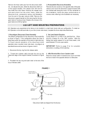
...for right hand mounting, refer to the disconnect shaft, set it aside. Remove the two E Rings securing the sprocket on page 4 for LGJ FIGURE 1 OPERATOR PREPARATION Model LGJ: Shipped from the limit chain, remove the chain and set the yoke aside. b) Provide a level base. For metal buildings, fasten ...DO SO. KEEP DOOR BALANCED. SITE PREPARATIONS It is imperative that the wall or mounting surface provide adequate support for model LGJ. Remove the screws securing the yoke to preparation instructions on the gear reducer shaft. CALL A PROFESSIONAL DOOR SERVICEMAN TO ...
...for right hand mounting, refer to the disconnect shaft, set it aside. Remove the two E Rings securing the sprocket on page 4 for LGJ FIGURE 1 OPERATOR PREPARATION Model LGJ: Shipped from the limit chain, remove the chain and set the yoke aside. b) Provide a level base. For metal buildings, fasten ...DO SO. KEEP DOOR BALANCED. SITE PREPARATIONS It is imperative that the wall or mounting surface provide adequate support for model LGJ. Remove the screws securing the yoke to preparation instructions on the gear reducer shaft. CALL A PROFESSIONAL DOOR SERVICEMAN TO ...
LGJ Manual
Page 4
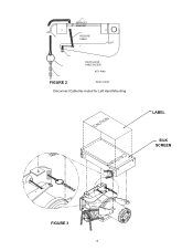
... are assembled at the factory to the illustration as shown in Figure 2. 3. To install an LGJ Operator on the left hand side of your door (motor side down , reconfigure as described below . 1. HOUR GLASS CABLE SLEEVE FIGURE 1 SLOT RELEASE CABLE SUPPORT ...
... are assembled at the factory to the illustration as shown in Figure 2. 3. To install an LGJ Operator on the left hand side of your door (motor side down , reconfigure as described below . 1. HOUR GLASS CABLE SLEEVE FIGURE 1 SLOT RELEASE CABLE SUPPORT ...
LGJ Manual
Page 5
SUPPORT BRACKET RELEASE CABLE SLOT HOUR GLASS CABLE SLEEVE KEY RING FIGURE 2 SASH CHAIN Disconnect Cable Re-routed for Left Hand Mounting LABEL SILK SCREEN FIGURE 3 5
SUPPORT BRACKET RELEASE CABLE SLOT HOUR GLASS CABLE SLEEVE KEY RING FIGURE 2 SASH CHAIN Disconnect Cable Re-routed for Left Hand Mounting LABEL SILK SCREEN FIGURE 3 5

LGJ Manual
Page 6
... mounted either above or below the door shaft. Bracket or Shelf Mounting The operator may be wall mounted or mounted on a bracket or shelf. OPTIONAL (LGJ) Mounting Bracket OPTIONAL (MGJ) Mounting Bracket P/N 10-9098 Typical Right Hand Wall Mounted Operator FIGURE 3 IMPORTANT: The shelf or bracket must provide adequate support, prevent...
... mounted either above or below the door shaft. Bracket or Shelf Mounting The operator may be wall mounted or mounted on a bracket or shelf. OPTIONAL (LGJ) Mounting Bracket OPTIONAL (MGJ) Mounting Bracket P/N 10-9098 Typical Right Hand Wall Mounted Operator FIGURE 3 IMPORTANT: The shelf or bracket must provide adequate support, prevent...
LGJ Manual
Page 7
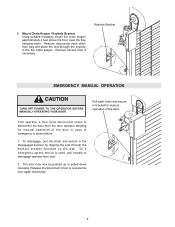
This operator a floor level disconnect chain to disconnect the door from the door operator allowing for manual operation of emergency or power failure. 1. Remove excess links if necessary. To disengage, pull the chain and secure in the disengaged position by slipping the end through the keyhole in bracket for manual operation of the door in case of the door. Or if emergency egress device is used, pull handle to operate the door again electrically. 7 6. Release the disconnect chain to disengage operator from bag and place the end through the keyhole bracket mounted on the...
This operator a floor level disconnect chain to disconnect the door from the door operator allowing for manual operation of emergency or power failure. 1. Remove excess links if necessary. To disengage, pull the chain and secure in the disengaged position by slipping the end through the keyhole in bracket for manual operation of the door in case of the door. Or if emergency egress device is used, pull handle to operate the door again electrically. 7 6. Release the disconnect chain to disengage operator from bag and place the end through the keyhole bracket mounted on the...

LGJ Manual
Page 8
If not pre-installed by either coiled cord or take-up reel should be electrically connected by the door manufacturer, mount the sensing edge on the door according to the instructions provided with the edge. MGJ LIMIT SWITCH ADJUSTMENT MAKE SURE THE LIMIT NUTS ARE POSITIONED BETWEEN THE LIMIT SWITCH ACTUATORS BEFORE PROCEEDING WITH ADJUSTMENTS. 1. If your door does not have a bottom sensing edge and you wish to operator as door fully seats at the floor. Repeat Steps 1 and 2 for CAUTION assistance - 1-800-528-2806. If other problems persist, call our toll-free number for ...
If not pre-installed by either coiled cord or take-up reel should be electrically connected by the door manufacturer, mount the sensing edge on the door according to the instructions provided with the edge. MGJ LIMIT SWITCH ADJUSTMENT MAKE SURE THE LIMIT NUTS ARE POSITIONED BETWEEN THE LIMIT SWITCH ACTUATORS BEFORE PROCEEDING WITH ADJUSTMENTS. 1. If your door does not have a bottom sensing edge and you wish to operator as door fully seats at the floor. Repeat Steps 1 and 2 for CAUTION assistance - 1-800-528-2806. If other problems persist, call our toll-free number for ...

LGJ Manual
Page 9
... limit nuts are traveling in the direction of the CLOSE limit switch or vice versa. pole 2 position is the OPEN limit. is "ON": Limit switch -A- LGJ LIMIT SWITCH ADJUSTMENT IMPORTANT NOTE: To avoid danger of possible damage to the door and operator, limit switches must be sure it engages in the...
... limit nuts are traveling in the direction of the CLOSE limit switch or vice versa. pole 2 position is the OPEN limit. is "ON": Limit switch -A- LGJ LIMIT SWITCH ADJUSTMENT IMPORTANT NOTE: To avoid danger of possible damage to the door and operator, limit switches must be sure it engages in the...
LGJ Manual
Page 10
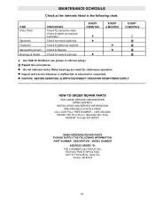
Time) MONDAY Through SATURDAY WHEN ORDERING REPAIR PARTS PLEASE SUPPLY THE FOLLOWING INFORMATION: PART NUMBER DESCRIPTION MODEL NUMBER ADDRESS ORDER TO: THE CHAMBERLAIN GROUP, INC. Forbes Blvd., Suite 104 Tucson, AZ 85745 10 Lubricate.* Check set screw tightness Check & tighten as required. Motor bearings are rated for excessive slack. CAUTION: BEFORE SERVICING, ALWAYS DISCONNECT OPERATOR FROM POWER SUPPLY. Repeat ALL procedures. Electronic Parts & Service Dept. 2301 N. HOW TO ORDER REPAIR PARTS OUR LARGE SERVICE ORGANIZATION SPANS AMERICA INSTALLATION AND SERVICE ...
Time) MONDAY Through SATURDAY WHEN ORDERING REPAIR PARTS PLEASE SUPPLY THE FOLLOWING INFORMATION: PART NUMBER DESCRIPTION MODEL NUMBER ADDRESS ORDER TO: THE CHAMBERLAIN GROUP, INC. Forbes Blvd., Suite 104 Tucson, AZ 85745 10 Lubricate.* Check set screw tightness Check & tighten as required. Motor bearings are rated for excessive slack. CAUTION: BEFORE SERVICING, ALWAYS DISCONNECT OPERATOR FROM POWER SUPPLY. Repeat ALL procedures. Electronic Parts & Service Dept. 2301 N. HOW TO ORDER REPAIR PARTS OUR LARGE SERVICE ORGANIZATION SPANS AMERICA INSTALLATION AND SERVICE ...
LGJ Manual
Page 11
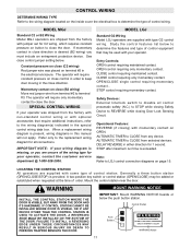
... department @ 1-800-528-2806. Refer only to the replacement wiring diagram for your operator was placed on close control in order to LGJ control connection diagrams on OPEN. WARNING INSTALL THE CONTROL STATION WHERE THE DOOR IS VISIBLE, BUT AWAY FROM THE DOOR AND ITS HARDWARE....Note: Refer to keep door moving in either direction for C2 wiring, which requires constant pressure on close the door. MODEL LGJ Standard G2 Wiring Model LGJ operators are supplied with momentary contact on page 15. Study the control features list below the push button station. Safety Devices:...
... department @ 1-800-528-2806. Refer only to the replacement wiring diagram for your operator was placed on close control in order to LGJ control connection diagrams on OPEN. WARNING INSTALL THE CONTROL STATION WHERE THE DOOR IS VISIBLE, BUT AWAY FROM THE DOOR AND ITS HARDWARE....Note: Refer to keep door moving in either direction for C2 wiring, which requires constant pressure on close the door. MODEL LGJ Standard G2 Wiring Model LGJ operators are supplied with momentary contact on page 15. Study the control features list below the push button station. Safety Devices:...
LGJ Manual
Page 12
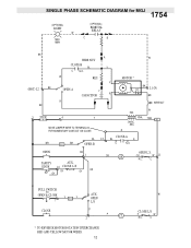
1754 SINGLE PHASE SCHEMATIC DIAGRAM for MGJ (OPTIONAL) LIGHT W MAX. 100W (OPTIONAL) BIMETAL RELAY C B BK A W WIRE NUT CLOSE-B BL Y C N.O. W RES. R BL 12 CLOSE-A BL R BR R1 BR OPEN-B C N.O. OR W 11 N.C. OPEN L/S CLOSE P P CL 2 * TO REVERSE MOTOR ROTATION INTERCHANGE RED AND YELLOW MOTOR WIRES. 12 W CLOSE L/S P W N.C. C PULL SWITCH TO OPEN & CLOSE 7 Y R2 Y AUX. Y (HOT) L2 BK OPEN-A Y CAPACITOR R MOTOR * BK O/L L1 (N) BR R BK 3 STOP 4 Y MOVE JUMPER WIRE TO TERMINAL #2 FOR MOMENTARY CONTACT ON CLOSE WIRE NUT W PR1. ...
1754 SINGLE PHASE SCHEMATIC DIAGRAM for MGJ (OPTIONAL) LIGHT W MAX. 100W (OPTIONAL) BIMETAL RELAY C B BK A W WIRE NUT CLOSE-B BL Y C N.O. W RES. R BL 12 CLOSE-A BL R BR R1 BR OPEN-B C N.O. OR W 11 N.C. OPEN L/S CLOSE P P CL 2 * TO REVERSE MOTOR ROTATION INTERCHANGE RED AND YELLOW MOTOR WIRES. 12 W CLOSE L/S P W N.C. C PULL SWITCH TO OPEN & CLOSE 7 Y R2 Y AUX. Y (HOT) L2 BK OPEN-A Y CAPACITOR R MOTOR * BK O/L L1 (N) BR R BK 3 STOP 4 Y MOVE JUMPER WIRE TO TERMINAL #2 FOR MOMENTARY CONTACT ON CLOSE WIRE NUT W PR1. ...
LGJ Manual
Page 13
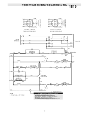
Constant Presssure to Close MOVE RED WIRE FROM TERMINAL #2 TO TERMINAL #3 13 1819 THREE PHASE SCHEMATIC DIAGRAM for MGJ 230V BRAKE (WHEN PRESENT) 230V BRAKE (WHEN PRESENT) BRN GY PUR YEL BRN BL/BK 1 74 2 85 3 96 O/L* BL/BK BRN GY PUR YEL BRN BL/BK 1 74 2 85 3 96 O/L* BL/BK 230 VOLT - 3 PHASE MOTOR CONNECTION 460 VOLT - 3 PHASE MOTOR CONNECTION L3 3 PHASE POWER IN L2 L1 3 (YEL) STOP OPEN SAFETY EDGE (OR) R1 (OR) (BK) (BK) (BK) (BR) EXTERNAL 4 INTERLOCK (GY) CL OP 4 3 OP 4 3 OP 2 1 CL 6 5 5 6 CL 1 2 (PUR) TO MOTOR (BK) (YEL) (BK) 5 (BRN) (YEL) 14 OP...
Constant Presssure to Close MOVE RED WIRE FROM TERMINAL #2 TO TERMINAL #3 13 1819 THREE PHASE SCHEMATIC DIAGRAM for MGJ 230V BRAKE (WHEN PRESENT) 230V BRAKE (WHEN PRESENT) BRN GY PUR YEL BRN BL/BK 1 74 2 85 3 96 O/L* BL/BK BRN GY PUR YEL BRN BL/BK 1 74 2 85 3 96 O/L* BL/BK 230 VOLT - 3 PHASE MOTOR CONNECTION 460 VOLT - 3 PHASE MOTOR CONNECTION L3 3 PHASE POWER IN L2 L1 3 (YEL) STOP OPEN SAFETY EDGE (OR) R1 (OR) (BK) (BK) (BK) (BR) EXTERNAL 4 INTERLOCK (GY) CL OP 4 3 OP 4 3 OP 2 1 CL 6 5 5 6 CL 1 2 (PUR) TO MOTOR (BK) (YEL) (BK) 5 (BRN) (YEL) 14 OP...

LGJ Manual
Page 15
... field control will only require momentary contact. ON: Maximum run time is 90 seconds. ON: CLOSE limit switch B OFF: CLOSE limit switch A MAXIMUM RUN TIME: 3 - LGJ CONTROL CONNECTION DIAGRAM 41B6 LISTED DOOR OPERATOR NUMBERED BOXES CORRESPOND WITH TERMINALS ON J1 CONNECTOR STRIP If Neccessary, Remove The Connector Block From The Board...
... field control will only require momentary contact. ON: Maximum run time is 90 seconds. ON: CLOSE limit switch B OFF: CLOSE limit switch A MAXIMUM RUN TIME: 3 - LGJ CONTROL CONNECTION DIAGRAM 41B6 LISTED DOOR OPERATOR NUMBERED BOXES CORRESPOND WITH TERMINALS ON J1 CONNECTOR STRIP If Neccessary, Remove The Connector Block From The Board...
LGJ Manual
Page 16
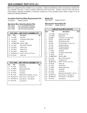
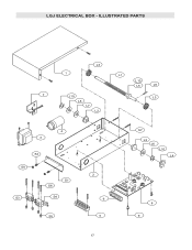
... Model LGJ2511 COMPLETE ELECTRICAL BOX KITS Item P/N Description QTY 1 10-11390M1 Electrical Box Cover 1 2 10-11392M1 Electrical Box 1 3 21-13395 Transformer, LGJ 115V-24VAC 1 4 29-7642 Capacitor 220V 42MFD 1 5 42-9306 Terminal Block 6 Pole 1 6 42-13378 J2 Terminal Block, 16 Pole (1-16...from these lists. Please consult a parts and service representative regarding availability of individual components of kits specified below. REPLACEMENT PART KITS LGJ Below are replacement kits available for RSL Assembly 1 L6 85-FW-38 Flat Washer, 3/8" 4 L7 86-RP04-012 Roll Pin...
... Model LGJ2511 COMPLETE ELECTRICAL BOX KITS Item P/N Description QTY 1 10-11390M1 Electrical Box Cover 1 2 10-11392M1 Electrical Box 1 3 21-13395 Transformer, LGJ 115V-24VAC 1 4 29-7642 Capacitor 220V 42MFD 1 5 42-9306 Terminal Block 6 Pole 1 6 42-13378 J2 Terminal Block, 16 Pole (1-16...from these lists. Please consult a parts and service representative regarding availability of individual components of kits specified below. REPLACEMENT PART KITS LGJ Below are replacement kits available for RSL Assembly 1 L6 85-FW-38 Flat Washer, 3/8" 4 L7 86-RP04-012 Roll Pin...
LGJ Manual
Page 17
ILLUSTRATED PARTS L3 1 L1 L10 L5 L9 7 L10 L3 L8 L7 L2 WARNING 4 3 S2 WARNING S8 S1 S6 S3 S4 S5 2 6 5 S7 L2 L6 L10 L4 8 9 17 LGJ ELECTRICAL BOX -
ILLUSTRATED PARTS L3 1 L1 L10 L5 L9 7 L10 L3 L8 L7 L2 WARNING 4 3 S2 WARNING S8 S1 S6 S3 S4 S5 2 6 5 S7 L2 L6 L10 L4 8 9 17 LGJ ELECTRICAL BOX -

LGJ Manual
Page 18
If optional modifications and/or accessories are included with your operator. MODEL LGJ Refer to page 10 for your operator, certain components may not be added or removed from these lists. K75-12583 DISCONNECT ASSEMBLY KIT INDIVIDUAL PARTS ...
If optional modifications and/or accessories are included with your operator. MODEL LGJ Refer to page 10 for your operator, certain components may not be added or removed from these lists. K75-12583 DISCONNECT ASSEMBLY KIT INDIVIDUAL PARTS ...
LGJ Manual
Page 19
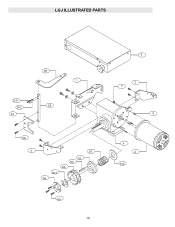
LGJ ILLUSTRATED PARTS D3 1 D11 D12 D5 D1 D9 3 D7 D2 D8 D6 D13 D4 D9 19 5 2 7 8 4 6 D10
LGJ ILLUSTRATED PARTS D3 1 D11 D12 D5 D1 D9 3 D7 D2 D8 D6 D13 D4 D9 19 5 2 7 8 4 6 D10

LGJ Manual
Page 20
Refer to page 10 for your operator. For replacement of electrical box, motor or brake components be sure to ensure proper voltage requirements. x .01 1 L6 85-FW-38 Flatwasher, 3/8" 2 L7 86-RP04-012 Roll Pin, 1/8" Dia. Single phase operators use relays. 2) Capacitor (29-10338), Capacitor Clamp (10-11421) and Resistor (29-2) used only on three phase operators. Complete Electrical Box Replacement Kits K-MGJ5011L Model MGJ5011L K-MGJ5023L Model MGJ5023L K-MGJ5025L Model MGJ5025L K-MGJ5038L Model MGJ5038L K-MGJ5043L Model MGJ5043L Motor Kits K20-1050C1M K20-3050C4M K20-...
Refer to page 10 for your operator. For replacement of electrical box, motor or brake components be sure to ensure proper voltage requirements. x .01 1 L6 85-FW-38 Flatwasher, 3/8" 2 L7 86-RP04-012 Roll Pin, 1/8" Dia. Single phase operators use relays. 2) Capacitor (29-10338), Capacitor Clamp (10-11421) and Resistor (29-2) used only on three phase operators. Complete Electrical Box Replacement Kits K-MGJ5011L Model MGJ5011L K-MGJ5023L Model MGJ5023L K-MGJ5025L Model MGJ5025L K-MGJ5038L Model MGJ5038L K-MGJ5043L Model MGJ5043L Motor Kits K20-1050C1M K20-3050C4M K20-...
LGJ Manual
Page 21
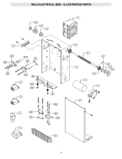
ILLUSTRATED PARTS 1 L8 L6 L2 9 S3 S9 S7 S4 S6 S3 S5 6 S2 S8 6 8 S3 S7 5 S1 S6 S4 S3 10 L3 L1 L7 3 L3 7 4 L2 L5 L4 2 21 MGJ ELECTRICAL BOX -
ILLUSTRATED PARTS 1 L8 L6 L2 9 S3 S9 S7 S4 S6 S3 S5 6 S2 S8 6 8 S3 S7 5 S1 S6 S4 S3 10 L3 L1 L7 3 L3 7 4 L2 L5 L4 2 21 MGJ ELECTRICAL BOX -