

LGJ Manual
Page 1
OWNER'S MANUAL MODELS: LGJ & MGJ INDUSTRIAL DUTY DOOR OPERATOR 2 YEAR WARRANTY Serial # (located on electrical box cover) Installation Date Wiring Type NOT FOR RESIDENTIAL USE 41B6 LISTED DOOR OPERATOR
OWNER'S MANUAL MODELS: LGJ & MGJ INDUSTRIAL DUTY DOOR OPERATOR 2 YEAR WARRANTY Serial # (located on electrical box cover) Installation Date Wiring Type NOT FOR RESIDENTIAL USE 41B6 LISTED DOOR OPERATOR

LGJ Manual
Page 2
... 3Ph 230V, 60Hz, 1Ph See pages 13 and 14 for emergency manual door operation. SAFETY DISCONNECT Floor level disconnect for optional control settings and operating modes. 380V, 50Hz, 3Ph 460V, 60Hz, 3Ph LGJ: 115V, 60Hz, 1Ph LIMIT ADJUST Linear driven, fully adjustable screw type cams.... Adjustable to the bottom edge of door A REVERSING EDGE IS STRONGLY RECOMMENDED FOR ALL COMMERCIAL OPERATOR INSTALLATIONS. REQUIRED WHEN ...
... 3Ph 230V, 60Hz, 1Ph See pages 13 and 14 for emergency manual door operation. SAFETY DISCONNECT Floor level disconnect for optional control settings and operating modes. 380V, 50Hz, 3Ph 460V, 60Hz, 3Ph LGJ: 115V, 60Hz, 1Ph LIMIT ADJUST Linear driven, fully adjustable screw type cams.... Adjustable to the bottom edge of door A REVERSING EDGE IS STRONGLY RECOMMENDED FOR ALL COMMERCIAL OPERATOR INSTALLATIONS. REQUIRED WHEN ...

LGJ Manual
Page 3
... DOOR SPRINGS, CABLES, PULLEYS, BRACKETS AND THEIR HARDWARE MAY BE UNDER EXTREME TENSION AND CAN CAUSE SERIOUS PERSONAL INJURY. c) Permit the operator to be fastened securely and with Bearing (Not Supplied) Door Sprocket The safety and wear of your unit. MGJ OPPOSITE HANDING PREPARATIONS 1.... on page 4 for Left hand mounting. See Figure 1. 22.-715/4fo" r MGJ, butt together for LGJ FIGURE 1 OPERATOR PREPARATION Model LGJ: Shipped from the factory for the operator. Refer to the conversion instructions below and on the gear reducer shaft. Refer to the last digit in the...
... DOOR SPRINGS, CABLES, PULLEYS, BRACKETS AND THEIR HARDWARE MAY BE UNDER EXTREME TENSION AND CAN CAUSE SERIOUS PERSONAL INJURY. c) Permit the operator to be fastened securely and with Bearing (Not Supplied) Door Sprocket The safety and wear of your unit. MGJ OPPOSITE HANDING PREPARATIONS 1.... on page 4 for Left hand mounting. See Figure 1. 22.-715/4fo" r MGJ, butt together for LGJ FIGURE 1 OPERATOR PREPARATION Model LGJ: Shipped from the factory for the operator. Refer to the conversion instructions below and on the gear reducer shaft. Refer to the last digit in the...
LGJ Manual
Page 4
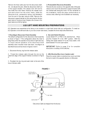
...screws on the opposite side of the support bracket. To install an LGJ Operator on setting of limit switches. 2. Re-attach the key ring and sash chain to be free... inside the motor frame. LGJ LEFT HAND MOUNTING PREPARATIONS LGJ Operators are assembled at the factory to the end of the loop of release cable. 3.... is read in figures 2 and 3. 1. This configuration allows the chain to hang freely when the operator is the open switch. Slide the disconnect hub, compression spring, and flatwasher from the disconnect shaft. Affix...
...screws on the opposite side of the support bracket. To install an LGJ Operator on setting of limit switches. 2. Re-attach the key ring and sash chain to be free... inside the motor frame. LGJ LEFT HAND MOUNTING PREPARATIONS LGJ Operators are assembled at the factory to the end of the loop of release cable. 3.... is read in figures 2 and 3. 1. This configuration allows the chain to hang freely when the operator is the open switch. Slide the disconnect hub, compression spring, and flatwasher from the disconnect shaft. Affix...

LGJ Manual
Page 6
... or mounting bracket. 5. Chain Keeper FIGURE 5 6 The operator may be mounted either above or below that suits your operator is installed, be wall mounted or mounted on a bracket or shelf. OPTIONAL (LGJ) Mounting Bracket OPTIONAL (MGJ) Mounting Bracket P/N 10-9098 Typical Right Hand Wall Mounted Operator FIGURE 3 IMPORTANT: The shelf or bracket must provide...
... or mounting bracket. 5. Chain Keeper FIGURE 5 6 The operator may be mounted either above or below that suits your operator is installed, be wall mounted or mounted on a bracket or shelf. OPTIONAL (LGJ) Mounting Bracket OPTIONAL (MGJ) Mounting Bracket P/N 10-9098 Typical Right Hand Wall Mounted Operator FIGURE 3 IMPORTANT: The shelf or bracket must provide...
LGJ Manual
Page 7
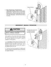
... wall. To disengage, pull the chain and secure in the disengaged position by slipping the end through the keyhole in case of the door. This operator a floor level disconnect chain to disconnect the door from door. 2. Or if emergency egress device is used, pull handle to... operate the door again electrically. 7 The door may now be pushed up or pulled down manually. Mount Chain Keeper / Keyhole Bracket Using suitable hardware mount the ...
... wall. To disengage, pull the chain and secure in the disengaged position by slipping the end through the keyhole in case of the door. This operator a floor level disconnect chain to disconnect the door from door. 2. Or if emergency egress device is used, pull handle to... operate the door again electrically. 7 The door may now be pushed up or pulled down manually. Mount Chain Keeper / Keyhole Bracket Using suitable hardware mount the ...

LGJ Manual
Page 8
... Switch Adjustments before making any sensing edge wiring connections to spin freely. To adjust limit nuts depress retaining plate to allow nut to operator as door fully seats at the floor. OPEN Limit Switch CLOSE Limit Switch Actuator SAFETY (Aux. ENTRAPMENT PROTECTION ACCESSORIES (OPTIONAL) SENSING ... is engaged as described below IT IS STRONGLY RECOMMENDED THAT A SENSING EDGE OR OTHER ENTRAPMENT PROTECTION DEVICE BE USED IN CONJUNCTION WITH THIS OPERATOR. If your door does not have a bottom sensing edge and you wish to the steps below . Refer to purchase one, contact ...
... Switch Adjustments before making any sensing edge wiring connections to spin freely. To adjust limit nuts depress retaining plate to allow nut to operator as door fully seats at the floor. OPEN Limit Switch CLOSE Limit Switch Actuator SAFETY (Aux. ENTRAPMENT PROTECTION ACCESSORIES (OPTIONAL) SENSING ... is engaged as described below IT IS STRONGLY RECOMMENDED THAT A SENSING EDGE OR OTHER ENTRAPMENT PROTECTION DEVICE BE USED IN CONJUNCTION WITH THIS OPERATOR. If your door does not have a bottom sensing edge and you wish to the steps below . Refer to purchase one, contact ...

LGJ Manual
Page 9
...) Dip Switch SW1 9 pole 2 setting above for adjustment of possible damage to the door and operator, limit switches must be confused with the CLOSE (right) limit nut. LGJ LIMIT SWITCH ADJUSTMENT IMPORTANT NOTE: To avoid danger of limit switches to their approximate positions before applying ...power to the operator. Limit Switch Layout Limit Switch -B(Top Switch) Limit Nut Limit Switch -A(Top Switch...
...) Dip Switch SW1 9 pole 2 setting above for adjustment of possible damage to the door and operator, limit switches must be confused with the CLOSE (right) limit nut. LGJ LIMIT SWITCH ADJUSTMENT IMPORTANT NOTE: To avoid danger of limit switches to their approximate positions before applying ...power to the operator. Limit Switch Layout Limit Switch -B(Top Switch) Limit Nut Limit Switch -A(Top Switch...
LGJ Manual
Page 10
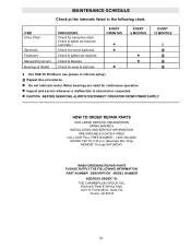
... 104 Tucson, AZ 85745 10 Lubricate.* Check set screw tightness Check & tighten as required. CAUTION: BEFORE SERVICING, ALWAYS DISCONNECT OPERATOR FROM POWER SUPPLY. Check & adjust as required Check & Operate Check for continuous operation. Do not lubricate motor. Time) MONDAY Through SATURDAY WHEN ORDERING REPAIR PARTS PLEASE SUPPLY THE FOLLOWING INFORMATION: PART NUMBER DESCRIPTION...
... 104 Tucson, AZ 85745 10 Lubricate.* Check set screw tightness Check & tighten as required. CAUTION: BEFORE SERVICING, ALWAYS DISCONNECT OPERATOR FROM POWER SUPPLY. Check & adjust as required Check & Operate Check for continuous operation. Do not lubricate motor. Time) MONDAY Through SATURDAY WHEN ORDERING REPAIR PARTS PLEASE SUPPLY THE FOLLOWING INFORMATION: PART NUMBER DESCRIPTION...
LGJ Manual
Page 11
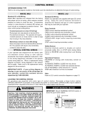
Refer only to the replacement wiring diagram for C2 wiring, which requires constant pressure on button to close direction. MODEL LGJ Standard G2 Wiring Model LGJ operators are shipped from terminal #2 to determine the type of control equipment that may be used with type G2 control wiring.... THE DOOR IS VISIBLE, BUT AWAY FROM THE DOOR AND ITS HARDWARE. Momentary contact on OPEN. The operator will require constant pressure on close control in order to LGJ control connection diagrams on terminal #2 in either direction for your wiring diagram is desired (B2 wiring) you...
Refer only to the replacement wiring diagram for C2 wiring, which requires constant pressure on button to close direction. MODEL LGJ Standard G2 Wiring Model LGJ operators are shipped from terminal #2 to determine the type of control equipment that may be used with type G2 control wiring.... THE DOOR IS VISIBLE, BUT AWAY FROM THE DOOR AND ITS HARDWARE. Momentary contact on OPEN. The operator will require constant pressure on close control in order to LGJ control connection diagrams on terminal #2 in either direction for your wiring diagram is desired (B2 wiring) you...

LGJ Manual
Page 15
LGJ CONTROL CONNECTION DIAGRAM 41B6 LISTED DOOR OPERATOR NUMBERED BOXES CORRESPOND WITH TERMINALS ON J1 CONNECTOR STRIP If Neccessary, Remove The Connector Block From The Board To Secure Each Wire Connection Connect field ...
LGJ CONTROL CONNECTION DIAGRAM 41B6 LISTED DOOR OPERATOR NUMBERED BOXES CORRESPOND WITH TERMINALS ON J1 CONNECTOR STRIP If Neccessary, Remove The Connector Block From The Board To Secure Each Wire Connection Connect field ...
LGJ Manual
Page 16
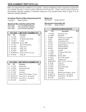
... Kit K75-12583 Model LGJ2511 COMPLETE ELECTRICAL BOX KITS Item P/N Description QTY 1 10-11390M1 Electrical Box Cover 1 2 10-11392M1 Electrical Box 1 3 21-13395 Transformer, LGJ 115V-24VAC 1 4 29-7642 Capacitor 220V 42MFD 1 5 42-9306 Terminal Block 6 Pole 1 6 42-13378 J2 Terminal Block, 16 Pole (1-16) 1 7...-PX06-16 Screw, #6-32 x 1" Pan Head Ph 2 S8 84-LH-06 Locknut #6-32 2 16 REPLACEMENT PART KITS LGJ Below are replacement kits available for your operator may add or remove certain components from these lists. Refer to page 10 for RSL Assembly 1 L6 85-FW-38 Flat...
... Kit K75-12583 Model LGJ2511 COMPLETE ELECTRICAL BOX KITS Item P/N Description QTY 1 10-11390M1 Electrical Box Cover 1 2 10-11392M1 Electrical Box 1 3 21-13395 Transformer, LGJ 115V-24VAC 1 4 29-7642 Capacitor 220V 42MFD 1 5 42-9306 Terminal Block 6 Pole 1 6 42-13378 J2 Terminal Block, 16 Pole (1-16) 1 7...-PX06-16 Screw, #6-32 x 1" Pan Head Ph 2 S8 84-LH-06 Locknut #6-32 2 16 REPLACEMENT PART KITS LGJ Below are replacement kits available for your operator may add or remove certain components from these lists. Refer to page 10 for RSL Assembly 1 L6 85-FW-38 Flat...

LGJ Manual
Page 18
REPLACEMENT PART LISTS - MODEL LGJ Refer to page 10 for your operator, certain components may not be added or removed from these lists. Individual components of individual components. x 1" Long 1 D13 87-E-075 E Ring 3/4" 1 18 Please consult a parts ... Flatwasher, 3/4" 1 D11 86-CP04-112 Cotter Pin 1/8" x 1-3/4" Long 1 D12 86-RP04-100 Roll Pin, 1/8" Dia. If optional modifications and/or accessories are included with your operator.
REPLACEMENT PART LISTS - MODEL LGJ Refer to page 10 for your operator, certain components may not be added or removed from these lists. Individual components of individual components. x 1" Long 1 D13 87-E-075 E Ring 3/4" 1 18 Please consult a parts ... Flatwasher, 3/4" 1 D11 86-CP04-112 Cotter Pin 1/8" x 1-3/4" Long 1 D12 86-RP04-100 Roll Pin, 1/8" Dia. If optional modifications and/or accessories are included with your operator.

LGJ Manual
Page 20
...Kits K20-1050C1M K20-3050C4M K20-5150C6M Model MGJ5011 Models MGJ5023,MGJ5038,MGJ5043 Model MGJ5025 Disconnect Assembly Kit K75-12567 Model MGJ Operators K-MGJ5011R K-MGJ5023R K-MGJ5025R K-MGJ5038R K-MGJ5043R Model MGJ5011R Model MGJ5023R Model MGJ5025R Model MGJ5038R Model MGJ5043R Electrical Box Sub-Assemblies... 1 L6 85-FW-38 Flatwasher, 3/8" 2 L7 86-RP04-012 Roll Pin, 1/8" Dia. Optional modifications and/or accessories included with your operator. Please consult a parts and service representative regarding availability of individual components of your unit to page 10 for your...
...Kits K20-1050C1M K20-3050C4M K20-5150C6M Model MGJ5011 Models MGJ5023,MGJ5038,MGJ5043 Model MGJ5025 Disconnect Assembly Kit K75-12567 Model MGJ Operators K-MGJ5011R K-MGJ5023R K-MGJ5025R K-MGJ5038R K-MGJ5043R Model MGJ5011R Model MGJ5023R Model MGJ5025R Model MGJ5038R Model MGJ5043R Electrical Box Sub-Assemblies... 1 L6 85-FW-38 Flatwasher, 3/8" 2 L7 86-RP04-012 Roll Pin, 1/8" Dia. Optional modifications and/or accessories included with your operator. Please consult a parts and service representative regarding availability of individual components of your unit to page 10 for your...

LGJ Manual
Page 22
... a parts and service representative regarding availability of each kit may be available. If optional modifications and/or accessories are included with your operator. Refer to the parts lists below for replacement kits available for all repair part ordering information. x 1" Long 1 D15 87-E-100... E Ring, 1" Plated 2 22 MODEL MGJ Refer to page 10 for your operator, certain components may not be added or removed from these lists. Of Sash Chain 1 D9 80-11416 Disconnect Key 1/4 x 1/4 x 7/8 2 D10 80...
... a parts and service representative regarding availability of each kit may be available. If optional modifications and/or accessories are included with your operator. Refer to the parts lists below for replacement kits available for all repair part ordering information. x 1" Long 1 D15 87-E-100... E Ring, 1" Plated 2 22 MODEL MGJ Refer to page 10 for your operator, certain components may not be added or removed from these lists. Of Sash Chain 1 D9 80-11416 Disconnect Key 1/4 x 1/4 x 7/8 2 D10 80...

LGJ Manual
Page 24
... WIRING TYPES TIMER TO CLOSE w/ WARNING LIGHT ALL CONTROL WIRING TYPES * T1 WIRING - MGJ CONTROL CONNECTION DIAGRAM IMPORTANT NOTES: (Refer to page 15 for model LGJ control connections) 1) The 3-Button Control Station provided must be placed between termianls 3 and 4. All rights Reserved USE 16 GAUGE OR HEAVIER WIRE 3) Auxiliary control equipment.... RADIO TO OPEN ONLY EXTERNAL INTERLOCK Warning Light will activate 15 sec. ATTENTION ELECTRICIAN: 2) If a STOP button is Used 4 5 4 5 Timer Defeat Switch Power Supply for operation.
... WIRING TYPES TIMER TO CLOSE w/ WARNING LIGHT ALL CONTROL WIRING TYPES * T1 WIRING - MGJ CONTROL CONNECTION DIAGRAM IMPORTANT NOTES: (Refer to page 15 for model LGJ control connections) 1) The 3-Button Control Station provided must be placed between termianls 3 and 4. All rights Reserved USE 16 GAUGE OR HEAVIER WIRE 3) Auxiliary control equipment.... RADIO TO OPEN ONLY EXTERNAL INTERLOCK Warning Light will activate 15 sec. ATTENTION ELECTRICIAN: 2) If a STOP button is Used 4 5 4 5 Timer Defeat Switch Power Supply for operation.


