

LGJ Manual
Page 2
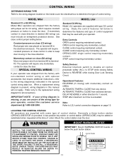
... WHEN THE 3 BUTTON CONTROL STATION IS OUT OF SIGHT OF DOOR OR ANY OTHER CONTROL (AUTOMATIC OR MANUAL) IS USED. OPEN/CLOSE/STOP SPEED MGJ: 1050 RPM LGJ: 1725 RPM VOLTAGE MGJ: 115, 60HZ, 1Ph WIRING TYPE: MGJ: B2-C2 (Factory Shipped) LGJ: G2 (Factory Shipped) 230V, 50 or 60Hz, 3Ph 230V..., 60Hz, 1Ph See pages 13 and 14 for emergency manual door operation. SAFETY DISCONNECT Floor...
... WHEN THE 3 BUTTON CONTROL STATION IS OUT OF SIGHT OF DOOR OR ANY OTHER CONTROL (AUTOMATIC OR MANUAL) IS USED. OPEN/CLOSE/STOP SPEED MGJ: 1050 RPM LGJ: 1725 RPM VOLTAGE MGJ: 115, 60HZ, 1Ph WIRING TYPE: MGJ: B2-C2 (Factory Shipped) LGJ: G2 (Factory Shipped) 230V, 50 or 60Hz, 3Ph 230V..., 60Hz, 1Ph See pages 13 and 14 for emergency manual door operation. SAFETY DISCONNECT Floor...

LGJ Manual
Page 3
... purlins together for model LGJ. KEYS SPRING DISC HUB SPROCKET E RING BRACKET YOKE SHAFT DISC LEVER 3 IMPORTANT SAFETY NOTES CAUTION WARWNAINRGNING W TO AVOID DAMAGE TO DOOR AND OPERATOR, MAKE ALL DOOR LOCKS INOPERATIVE. SECURE LOCK(S) IN "OPEN" POSITION. STICKING OR BINDING DOORS MUST BE REPAIRED. CALL A PROFESSIONAL DOOR SERVICEMAN TO MOVE OR ADJUST DOOR CAUTION SPRINGS OR...
... purlins together for model LGJ. KEYS SPRING DISC HUB SPROCKET E RING BRACKET YOKE SHAFT DISC LEVER 3 IMPORTANT SAFETY NOTES CAUTION WARWNAINRGNING W TO AVOID DAMAGE TO DOOR AND OPERATOR, MAKE ALL DOOR LOCKS INOPERATIVE. SECURE LOCK(S) IN "OPEN" POSITION. STICKING OR BINDING DOORS MUST BE REPAIRED. CALL A PROFESSIONAL DOOR SERVICEMAN TO MOVE OR ADJUST DOOR CAUTION SPRINGS OR...
LGJ Manual
Page 4
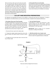
... Disconnect Chain Assembly The default configuration for complete instructions on the left hand side of your door (motor side down , reconfigure as described below . 1. Set Limit Switch Direction Locate Switch...the release cable through the slot on electrical box cover such that the text is the open switch. Slide the disconnect shaft out of Switch #1 in Figure 1. Replace the screws ...the three steps described below and as shipped from the disconnect shaft. LGJ LEFT HAND MOUNTING PREPARATIONS LGJ Operators are assembled at the factory to the illustration as shown in reverse...
... Disconnect Chain Assembly The default configuration for complete instructions on the left hand side of your door (motor side down , reconfigure as described below . 1. Set Limit Switch Direction Locate Switch...the release cable through the slot on electrical box cover such that the text is the open switch. Slide the disconnect shaft out of Switch #1 in Figure 1. Replace the screws ...the three steps described below and as shipped from the disconnect shaft. LGJ LEFT HAND MOUNTING PREPARATIONS LGJ Operators are assembled at the factory to the illustration as shown in reverse...

LGJ Manual
Page 8
... Switch Adjustments before making any sensing edge wiring connections to the wall approximately halfway up the door opening . 4. After adjustment, release plate and ensure it seats fully in open limit nut so that actuator is engaged as described below IT IS STRONGLY RECOMMENDED THAT A SENSING...close cycle. If other problems persist, call our toll-free number for close limit nut so that door will stop in slots of door opening . OPEN Limit Switch 8 To increase door travel , spin limit nut toward actuator. b) Electrician must hardwire the junction box to the instructions ...
... Switch Adjustments before making any sensing edge wiring connections to the wall approximately halfway up the door opening . 4. After adjustment, release plate and ensure it seats fully in open limit nut so that actuator is engaged as described below IT IS STRONGLY RECOMMENDED THAT A SENSING...close cycle. If other problems persist, call our toll-free number for close limit nut so that door will stop in slots of door opening . OPEN Limit Switch 8 To increase door travel , spin limit nut toward actuator. b) Electrician must hardwire the junction box to the instructions ...

LGJ Manual
Page 9
... switch and may cause damage to both limit nuts. Limit Switch -A(Bottom Switch) Dip Switch SW1 9 LGJ LIMIT SWITCH ADJUSTMENT IMPORTANT NOTE: To avoid danger of possible damage to the door and operator, limit switches must be confused with the CLOSE (right) limit nut. WARNING NEVER PLACE HANDS...SW1 - There are WARNING also present and should not be adjusted to their final, exact position. Manually raise the door to a nearly open position to avoid damage due to OPEN when the limit nuts are traveling in the slots of the limit travel . When power is the CLOSE limit. In...
... switch and may cause damage to both limit nuts. Limit Switch -A(Bottom Switch) Dip Switch SW1 9 LGJ LIMIT SWITCH ADJUSTMENT IMPORTANT NOTE: To avoid danger of possible damage to the door and operator, limit switches must be confused with the CLOSE (right) limit nut. WARNING NEVER PLACE HANDS...SW1 - There are WARNING also present and should not be adjusted to their final, exact position. Manually raise the door to a nearly open position to avoid damage due to OPEN when the limit nuts are traveling in the slots of the limit travel . When power is the CLOSE limit. In...
LGJ Manual
Page 11
... Note: Refer to LGJ control connection diagrams on close (B2 wiring) Move red jumper wire from terminal #2 to terminal #3. WARNING INSTALL THE CONTROL STATION WHERE THE DOOR IS VISIBLE, BUT AWAY FROM THE DOOR AND ITS HARDWARE. Control Station Push Buttons OPEN WARNING WARNING CLOSE TO... PREVENT ENTRAPMENT DO NOT START DOOR DOWNWARD UNLESS DOORWAY IS CLEAR STOP WARNING Notice 11 LOCATING THE...
... Note: Refer to LGJ control connection diagrams on close (B2 wiring) Move red jumper wire from terminal #2 to terminal #3. WARNING INSTALL THE CONTROL STATION WHERE THE DOOR IS VISIBLE, BUT AWAY FROM THE DOOR AND ITS HARDWARE. Control Station Push Buttons OPEN WARNING WARNING CLOSE TO... PREVENT ENTRAPMENT DO NOT START DOOR DOWNWARD UNLESS DOORWAY IS CLEAR STOP WARNING Notice 11 LOCATING THE...

LGJ Manual
Page 15
... only require momentary contact and will set or reset timer to close . 8 - Open control will only require momentary contact and will NOT set or reset timer to keep door moving . 9 - DO NOT add unless using an entrapment Protection device. 15 SWITCH ADJUSTMENTS SWITCH ... 3 TO TERMINAL 5. 3 5 OPEN AND CLOSE CONTROL OPTIONS WHEN CONNECTING AN OPEN CONTROL TO: 11 - Close control will function for explanation of how field control will only require momentary contact. LGJ CONTROL CONNECTION DIAGRAM 41B6 LISTED DOOR OPERATOR NUMBERED BOXES CORRESPOND WITH TERMINALS ON...
... only require momentary contact and will set or reset timer to close . 8 - Open control will only require momentary contact and will NOT set or reset timer to keep door moving . 9 - DO NOT add unless using an entrapment Protection device. 15 SWITCH ADJUSTMENTS SWITCH ... 3 TO TERMINAL 5. 3 5 OPEN AND CLOSE CONTROL OPTIONS WHEN CONNECTING AN OPEN CONTROL TO: 11 - Close control will function for explanation of how field control will only require momentary contact. LGJ CONTROL CONNECTION DIAGRAM 41B6 LISTED DOOR OPERATOR NUMBERED BOXES CORRESPOND WITH TERMINALS ON...

LGJ Manual
Page 24
... DIAGRAM IMPORTANT NOTES: (Refer to page 15 for model LGJ control connections) 1) The 3-Button Control Station provided must be placed between termianls 3 and 4. RADIO TO OPEN ONLY EXTERNAL INTERLOCK Warning Light will activate 15 sec. before door closes. 11 12 13 14 Auxiliary Terminal Block Remove Jumper... When Interlock is not used, a jumper must be any normally open two wire device such as FOR ALL CONTROL...
... DIAGRAM IMPORTANT NOTES: (Refer to page 15 for model LGJ control connections) 1) The 3-Button Control Station provided must be placed between termianls 3 and 4. RADIO TO OPEN ONLY EXTERNAL INTERLOCK Warning Light will activate 15 sec. before door closes. 11 12 13 14 Auxiliary Terminal Block Remove Jumper... When Interlock is not used, a jumper must be any normally open two wire device such as FOR ALL CONTROL...


