
User Guide
Page 2
... (such as translation, transformation, or adaptation) without warranty, term, or condition of Netscape Communications. it is the policy of 3Com Corporation to , the implied warranties, terms or conditions of merchantability, satisfactory quality, and fitness for this product is provided with ... limited rights only as a separate document, in the hard copy documentation, or on a continual basis. End of Life Statement 3Com processes allow for the Software. Ensuring that all operations. If there is any hazardous or ozone-depleting material. Maximizing the recyclable...
... (such as translation, transformation, or adaptation) without warranty, term, or condition of Netscape Communications. it is the policy of 3Com Corporation to , the implied warranties, terms or conditions of merchantability, satisfactory quality, and fitness for this product is provided with ... limited rights only as a separate document, in the hard copy documentation, or on a continual basis. End of Life Statement 3Com processes allow for the Software. Ensuring that all operations. If there is any hazardous or ozone-depleting material. Maximizing the recyclable...
User Guide
Page 3
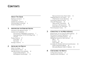
... INTRODUCING THE BASELINE SWITCH Overview of the Baseline Switch 7 Features and Capabilities 7 Autosensing of MDI/MDIX Connections 7 Autonegotiating 10/100/1000 Mbps Ports 7 SFP Ports 7 Physical Features 8 Front Panel 8 Rear Panel 11 Package Contents 11 2 INSTALLING THE SWITCH Before You Begin 13 Positioning the Switch 13 Rack-...of Each Other 15 Supplying Power to the Switch 16 Checking for Correct Operation 16 Connecting a Network Device 17 Using SFP Transceivers 18 Approved SFP Transceivers 18 Inserting an SFP Transceiver 18 Removing an SFP Transceiver 19 Performing Spot Checks 19 3 CONNECTING...
... INTRODUCING THE BASELINE SWITCH Overview of the Baseline Switch 7 Features and Capabilities 7 Autosensing of MDI/MDIX Connections 7 Autonegotiating 10/100/1000 Mbps Ports 7 SFP Ports 7 Physical Features 8 Front Panel 8 Rear Panel 11 Package Contents 11 2 INSTALLING THE SWITCH Before You Begin 13 Positioning the Switch 13 Rack-...of Each Other 15 Supplying Power to the Switch 16 Checking for Correct Operation 16 Connecting a Network Device 17 Using SFP Transceivers 18 Approved SFP Transceivers 18 Inserting an SFP Transceiver 18 Removing an SFP Transceiver 19 Performing Spot Checks 19 3 CONNECTING...

User Guide
Page 4
Changing the Admin Password 28 Modifying the IP Address Settings 29 Automatic IP Configuration 29 Setting the IP Address 30 Configuring Port Settings 31 Basic Port Configuration 31 Advanced Port Configuration 33 Configuring VLANs 33 Creating a VLAN 34 Sample VLAN Configurations 35 Removing a VLAN 37 Configuring Link Aggregation 37 Guidelines for Creating Aggregated Links 38 Defining the Members of an Aggregated Link 38 Modifying Settings and Deleting an Aggregated Link 39 Viewing the Trunk Summary 39 Viewing Statistics 40 Mirroring Port Traffic 41 Running Cable Diagnostic 42 Using the System ...
Changing the Admin Password 28 Modifying the IP Address Settings 29 Automatic IP Configuration 29 Setting the IP Address 30 Configuring Port Settings 31 Basic Port Configuration 31 Advanced Port Configuration 33 Configuring VLANs 33 Creating a VLAN 34 Sample VLAN Configurations 35 Removing a VLAN 37 Configuring Link Aggregation 37 Guidelines for Creating Aggregated Links 38 Defining the Members of an Aggregated Link 38 Modifying Settings and Deleting an Aggregated Link 39 Viewing the Trunk Summary 39 Viewing Statistics 40 Mirroring Port Traffic 41 Running Cable Diagnostic 42 Using the System ...
User Guide
Page 5
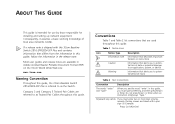
...alerts you to potential loss of local area networks (LANs). Most user guides and release notes are linked with this 3Com Baseline Switch 2816-SFP/2824-SFP Plus and contains information that alerts you to an application, system, or device Warning Information that differs from the information in ...this guide, follow the information in this guide, the 3Com Baseline Switch 2816/2824-SFP Plus is referred to as the Switch. If a release note is intended for use by those responsible for installing and setting up network equipment.
...alerts you to potential loss of local area networks (LANs). Most user guides and release notes are linked with this 3Com Baseline Switch 2816-SFP/2824-SFP Plus and contains information that alerts you to an application, system, or device Warning Information that differs from the information in ...this guide, follow the information in this guide, the 3Com Baseline Switch 2816/2824-SFP Plus is referred to as the Switch. If a release note is intended for use by those responsible for installing and setting up network equipment.
User Guide
Page 6
... latest product information and to -date information on your Baseline Switch on the 3Com Web site to receive up-to order these products. Please e-mail comments about this document to 3Com at the place where it is defined in italics Description...on the title page) ■ Page number (if appropriate) Example: ■ 3Com Baseline Switch 2816-SFP/2824-SFP Plus User Guide ■ Part Number DUA1648-5AAA03 ■ Page 24 Do not use this guide, each 3Com Baseline Switch 2816-SFP/2824-SFP Plus documentation set includes the following: ■ Online Help - 6 ABOUT THIS GUIDE...
... latest product information and to -date information on your Baseline Switch on the 3Com Web site to receive up-to order these products. Please e-mail comments about this document to 3Com at the place where it is defined in italics Description...on the title page) ■ Page number (if appropriate) Example: ■ 3Com Baseline Switch 2816-SFP/2824-SFP Plus User Guide ■ Part Number DUA1648-5AAA03 ■ Page 24 Do not use this guide, each 3Com Baseline Switch 2816-SFP/2824-SFP Plus documentation set includes the following: ■ Online Help - 6 ABOUT THIS GUIDE...
User Guide
Page 7
... duplex mode of Gigabit links, but do not need sophisticated management capabilities. Autosensing of the Baseline Switch The 3Com Baseline Switch 2816-SFP/2824-SFP Plus is necessary. No configuration is a versatile, easy-to another switch port, server, or workstation without additional configuration. 1 INTRODUCING THE BASELINE SWITCH This chapter provides an overview of the features and capabilities of the device. It also...
... duplex mode of Gigabit links, but do not need sophisticated management capabilities. Autosensing of the Baseline Switch The 3Com Baseline Switch 2816-SFP/2824-SFP Plus is necessary. No configuration is a versatile, easy-to another switch port, server, or workstation without additional configuration. 1 INTRODUCING THE BASELINE SWITCH This chapter provides an overview of the features and capabilities of the device. It also...
User Guide
Page 8
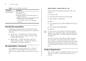
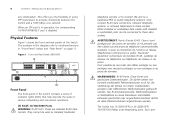
... or Netztelefone an diese Steckdosen anschließen. When an SFP port is in this diagram refer to provide connectivity between the Switch and a 1000 Mbps core network. Figure 1 Front and Rear Panels (2816-SFP) 1 1 9 8 4 5 12 13 Baseline Switch 2816-SFP Plus Module Present 8 16 Link/Activity : Green = 1000M, ...233;phones de réseaux à ces prises. Each port The Switch has 16 (2816-SFP) or 24 (2824-SFP) 10/100/1000 Mbps auto-negotiating ports. This offers you the flexibility of using SFP transceivers to numbered sections in "Front Panel" below and "Rear Panel"...
... or Netztelefone an diese Steckdosen anschließen. When an SFP port is in this diagram refer to provide connectivity between the Switch and a 1000 Mbps core network. Figure 1 Front and Rear Panels (2816-SFP) 1 1 9 8 4 5 12 13 Baseline Switch 2816-SFP Plus Module Present 8 16 Link/Activity : Green = 1000M, ...233;phones de réseaux à ces prises. Each port The Switch has 16 (2816-SFP) or 24 (2824-SFP) 10/100/1000 Mbps auto-negotiating ports. This offers you the flexibility of using SFP transceivers to numbered sections in "Front Panel" below and "Rear Panel"...
User Guide
Page 9
... in full duplex mode). Flashing Packets are auto-negotiating: their status according to 24 (2824-SFP) on the Yellow port at 1000 Mbps. When an SFP port is active, it is enabled, if it has priority over the 10/100/1000 port of auto-negotiation (...a configurable option). (2) SFP Ports The Small Form Factor Pluggable (SFP) ports are numbered 13 to 24 (2824-SFP) are being received or transmitted on the Switch. Flashing Packets are capable of the same number. In such a configuration, you may notice some degradation of network performance. 3Com recommends that you the ...
... in full duplex mode). Flashing Packets are auto-negotiating: their status according to 24 (2824-SFP) on the Yellow port at 1000 Mbps. When an SFP port is active, it is enabled, if it has priority over the 10/100/1000 port of auto-negotiation (...a configurable option). (2) SFP Ports The Small Form Factor Pluggable (SFP) ports are numbered 13 to 24 (2824-SFP) are being received or transmitted on the Switch. Flashing Packets are capable of the same number. In such a configuration, you may notice some degradation of network performance. 3Com recommends that you the ...
User Guide
Page 10
10 CHAPTER 1: INTRODUCING THE BASELINE SWITCH Table 1 10BASE-T/100BASE-TX Ports Flashing Port disabled or link loopback...fiber connections, ensure that the attached device is powered on self test or loopback test failed. Off No fiber SFP is inserted in full-duplex mode. (6) Power LED The Power LED shows the power status of the related ...Check that are not swapped. Table 2 Module Active LEDs Status Meaning Green Fiber SFP is faulty. If these checks do not identify the cause of any SFP modules that the cable or fiber is the correct type and is connected correctly....
10 CHAPTER 1: INTRODUCING THE BASELINE SWITCH Table 1 10BASE-T/100BASE-TX Ports Flashing Port disabled or link loopback...fiber connections, ensure that the attached device is powered on self test or loopback test failed. Off No fiber SFP is inserted in full-duplex mode. (6) Power LED The Power LED shows the power status of the related ...Check that are not swapped. Table 2 Module Active LEDs Status Meaning Green Fiber SFP is faulty. If these checks do not identify the cause of any SFP modules that the cable or fiber is the correct type and is connected correctly....
User Guide
Page 11
...the pads locate with the unit. (9) Recovery button The recovery button reinitializes the Switch. The Switch comes with four self-adhesive rubber pads. If you have forgotten the default IP address, or forgotten your 3Com network supplier immediately. Only use the power cord that you back up your ...configuration settings before you recover the Switch, otherwise your configuration will be part of a free-standing stack, apply the ...
...the pads locate with the unit. (9) Recovery button The recovery button reinitializes the Switch. The Switch comes with four self-adhesive rubber pads. If you have forgotten the default IP address, or forgotten your 3Com network supplier immediately. Only use the power cord that you back up your ...configuration settings before you recover the Switch, otherwise your configuration will be part of a free-standing stack, apply the ...

User Guide
Page 12
12 CHAPTER 1: INTRODUCING THE BASELINE SWITCH
12 CHAPTER 1: INTRODUCING THE BASELINE SWITCH
User Guide
Page 13
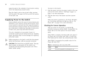
... du Switch ou ...;curité. ADVERTENCIA: Información de Seguridad. Positioning the Switch The Switch is suitable for use in an office environment where it can... guide. Before installing or removing any components from the Switch or carrying out any maintenance procedures, read the safety...9632; Positioning the Switch ■ Rack-Mounting or Free-Standing ■ Supplying Power to install and set up the Switch. Prima di ...per l'utente. Bevor Sie Komponenten aus dem Switch entfernen oder dem Switch hinzufuegen oder Instandhaltungsarbeiten verrichten, lesen Sie die Sicherheitsanweisungen, die ...
... du Switch ou ...;curité. ADVERTENCIA: Información de Seguridad. Positioning the Switch The Switch is suitable for use in an office environment where it can... guide. Before installing or removing any components from the Switch or carrying out any maintenance procedures, read the safety...9632; Positioning the Switch ■ Rack-Mounting or Free-Standing ■ Supplying Power to install and set up the Switch. Prima di ...per l'utente. Bevor Sie Komponenten aus dem Switch entfernen oder dem Switch hinzufuegen oder Instandhaltungsarbeiten verrichten, lesen Sie die Sicherheitsanweisungen, die ...
User Guide
Page 14
...the unit and through the vents in the side of the case is not restricted (3Com recommends that you should take note of dust as free of the guidelines given in "Positioning the Switch" on page 13. Do not place objects on copper cabling and introduce errors, ...wiring closet or equipment room. Electromagnetic fields can be installed above the larger ones. CAUTION: If installing the Switch in contact with the Switch. Do not have a free-standing stack of different size Baseline or Superstack® 3 units, the smaller units must be connected easily. ■ Cabling is always ...
...the unit and through the vents in the side of the case is not restricted (3Com recommends that you should take note of dust as free of the guidelines given in "Positioning the Switch" on page 13. Do not place objects on copper cabling and introduce errors, ...wiring closet or equipment room. Electromagnetic fields can be installed above the larger ones. CAUTION: If installing the Switch in contact with the Switch. Do not have a free-standing stack of different size Baseline or Superstack® 3 units, the smaller units must be connected easily. ■ Cabling is always ...
User Guide
Page 16
...black outs, power dips and electrical storms. The unit is clean and free from lightning and power surges. We recommend that you power on the Switch, it automatically performs a power-on self-test (POST). This is complete, the Power LED turns green. Checking for use . Installing proper ...the rear panel of the power cord into the power socket on page 11 for more information. To power on and power off the Switch is connected to avoid unforeseen network outages. Table 5Table 5 summarizes the possible colors for the Power LED after POST, it is by connecting...
...black outs, power dips and electrical storms. The unit is clean and free from lightning and power surges. We recommend that you power on the Switch, it automatically performs a power-on self-test (POST). This is complete, the Power LED turns green. Checking for use . Installing proper ...the rear panel of the power cord into the power socket on page 11 for more information. To power on and power off the Switch is connected to avoid unforeseen network outages. Table 5Table 5 summarizes the possible colors for the Power LED after POST, it is by connecting...
User Guide
Page 17
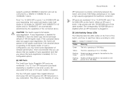
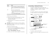
... mode. Color Yellow Off State Power-on again. The Switch is connected correctly, and then try powering on the Switch again ■ If the Switch still does not operate, contact your 3Com network supplier If POST fails, try the following: ■... or ports fail when the Switch was successfully completed. ■ Reset the Switch. Figure 3 Connecting Devices to the Switch Baseline 10/100 Switch Endstations on switched 100 Mbps connections Baseline 10/100 Switch Endstations on switched 100 Mbps connections BaselineBSawsietclihne28S1w6i/t2ch82242-5S0FP Plus 1000 Mbps copper or F iber...
... mode. Color Yellow Off State Power-on again. The Switch is connected correctly, and then try powering on the Switch again ■ If the Switch still does not operate, contact your 3Com network supplier If POST fails, try the following: ■... or ports fail when the Switch was successfully completed. ■ Reset the Switch. Figure 3 Connecting Devices to the Switch Baseline 10/100 Switch Endstations on switched 100 Mbps connections Baseline 10/100 Switch Endstations on switched 100 Mbps connections BaselineBSawsietclihne28S1w6i/t2ch82242-5S0FP Plus 1000 Mbps copper or F iber...
User Guide
Page 18
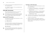
... time of publication: ■ 3CSFP91 SFP (SX) ■ 3CSFP92 SFP (LX) To access the latest list of approved SFP transceivers is closed (in Figure 4. For 1000BASE-T operation, 3Com recommends using 3Com SFPs on the 3Com Corporation World Wide Web site, enter this URL into any SFP port without having to power off the Switch. Using SFP Transceivers The following : ■...
... time of publication: ■ 3CSFP91 SFP (SX) ■ 3CSFP92 SFP (LX) To access the latest list of approved SFP transceivers is closed (in Figure 4. For 1000BASE-T operation, 3Com recommends using 3Com SFPs on the 3Com Corporation World Wide Web site, enter this URL into any SFP port without having to power off the Switch. Using SFP Transceivers The following : ■...
User Guide
Page 19
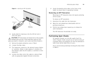
... are keyed and can be least effect on users. 3Com recommends periodically checking the items listed in Table 6. Removing an SFP Transceiver Removing an SFP transceiver does not require powering off the Switch. Performing Spot Checks At frequent intervals, you an early warning of a possible failure; If the... until it is pointing toward you. 3 Pull the wire release lever toward you to release the catch mechanism. The SFP transceiver should visually check the Switch. Regular checks can then be attended to when there will be properly inserted only one way. Performing Spot Checks 19 ...
... are keyed and can be least effect on users. 3Com recommends periodically checking the items listed in Table 6. Removing an SFP Transceiver Removing an SFP transceiver does not require powering off the Switch. Performing Spot Checks At frequent intervals, you an early warning of a possible failure; If the... until it is pointing toward you. 3 Pull the wire release lever toward you to release the catch mechanism. The SFP transceiver should visually check the Switch. Regular checks can then be attended to when there will be properly inserted only one way. Performing Spot Checks 19 ...
User Guide
Page 20
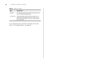
20 CHAPTER 2: INSTALLING THE SWITCH Table 6 Items to Check Item Verify That Cabling All external cabling connections are secure and that no cables are pulled taut Cooling Fan Where possible, check that the cooling fan is fitted on page 49. The fan is operating by listening to "Troubleshooting" on the right side of the unit (when viewed from the front). If you experience any problems operating the Switch, refer to the unit.
20 CHAPTER 2: INSTALLING THE SWITCH Table 6 Items to Check Item Verify That Cabling All external cabling connections are secure and that no cables are pulled taut Cooling Fan Where possible, check that the cooling fan is fitted on page 49. The fan is operating by listening to "Troubleshooting" on the right side of the unit (when viewed from the front). If you experience any problems operating the Switch, refer to the unit.
User Guide
Page 21
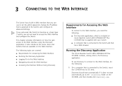
... the CD-ROM into its advanced settings. It also introduces the menu items and buttons that is assigned to the Switch and that has a Web browser Running the Discovery Application The 3Com Baseline Switch 2816-SFP/2824-SFP Plus CD-ROM contains, among others, the Discovery application. This chapter provides information on the CD-ROM, and then double...
... the CD-ROM into its advanced settings. It also introduces the menu items and buttons that is assigned to the Switch and that has a Web browser Running the Discovery Application The 3Com Baseline Switch 2816-SFP/2824-SFP Plus CD-ROM contains, among others, the Discovery application. This chapter provides information on the CD-ROM, and then double...
User Guide
Page 22
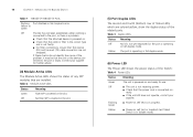
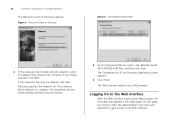
... enter the administration user name and password to gain access to the Switch, and then click Next. The Web interface loads in your Web browser. Discovery searches the network for 3Com devices. When detection is the logon page. Logging On to the ...Discovered Devices screen displays detected network devices. 3 On the Discovered Devices screen, click Baseline Switch 2816-SFP/2824-SFP Plus, and then click Next. If the computer has only one adapter, click Next. The Completing the 3Com Discovery Application screen appears. 4 Click Finish. Figure 5 Welcome Screen of Discovery appears...
... enter the administration user name and password to gain access to the Switch, and then click Next. The Web interface loads in your Web browser. Discovery searches the network for 3Com devices. When detection is the logon page. Logging On to the ...Discovered Devices screen displays detected network devices. 3 On the Discovered Devices screen, click Baseline Switch 2816-SFP/2824-SFP Plus, and then click Next. If the computer has only one adapter, click Next. The Completing the 3Com Discovery Application screen appears. 4 Click Finish. Figure 5 Welcome Screen of Discovery appears...