Getting Started Guide
Page 3
... Online Documentation 10 Product Registration 10 Documentation Comments 10 1 INTRODUCING THE SUPERSTACK 3 SWITCH 4200 SERIES About the Switch 4200 Series 12 Summary of Each Other 23 Stacking Units 23 The Power-up Sequence 24 Powering-up the Switch 4200 Series 24 Front View Detail 13 10BASE-T/ 100BASE-TX Ports 14... 10/100/1000BASE-T Ports 14 GBIC Ports 14 LEDs 15 Switch 4200 Series - Rear View Detail 17 Power Socket 17 Redundant Power System Socket 17 Console Port 17 Default Settings 18 2 INSTALLING THE SWITCH Package Contents 20 Choosing a Suitable Site 20 Rack-mounting 21 Placing...
... Online Documentation 10 Product Registration 10 Documentation Comments 10 1 INTRODUCING THE SUPERSTACK 3 SWITCH 4200 SERIES About the Switch 4200 Series 12 Summary of Each Other 23 Stacking Units 23 The Power-up Sequence 24 Powering-up the Switch 4200 Series 24 Front View Detail 13 10BASE-T/ 100BASE-TX Ports 14... 10/100/1000BASE-T Ports 14 GBIC Ports 14 LEDs 15 Switch 4200 Series - Rear View Detail 17 Power Socket 17 Redundant Power System Socket 17 Console Port 17 Default Settings 18 2 INSTALLING THE SWITCH Package Contents 20 Choosing a Suitable Site 20 Rack-mounting 21 Placing...
Getting Started Guide
Page 4
Checking for Correct Operation of LEDs 24 Connecting a Redundant Power System 25 Choosing the Correct Cables 25 Choosing the correct Fiber cables 26 GBIC Operation 27 Approved GBIC Transceivers 27 Inserting a GBIC Transceiver 27 3 SETTING ... Connecting to a Front Panel Port 35 Connecting to the Console Port 38 Viewing Automatically Configured IP Information 42 Using 3Com Network Supervisor 42 Connecting to the Console Port 42 Methods of Managing a Switch 45 Command Line Interface Management 45 Web Interface Management 46 SNMP Management 46 Setting Up Command Line Interface Management...
Checking for Correct Operation of LEDs 24 Connecting a Redundant Power System 25 Choosing the Correct Cables 25 Choosing the correct Fiber cables 26 GBIC Operation 27 Approved GBIC Transceivers 27 Inserting a GBIC Transceiver 27 3 SETTING ... Connecting to a Front Panel Port 35 Connecting to the Console Port 38 Viewing Automatically Configured IP Information 42 Using 3Com Network Supervisor 42 Connecting to the Console Port 42 Methods of Managing a Switch 45 Command Line Interface Management 45 Web Interface Management 46 SNMP Management 46 Setting Up Command Line Interface Management...
Getting Started Guide
Page 9
... CD-ROM that enable you may find useful, such as: ■ Documentation accompanying the Advanced Redundant Power system. ■ Documentation accompanying 3Com Network Supervisor. Related Documentation 9 Related Documentation In addition to this guide, each Switch documentation set includes the following: ■ SuperStack 3 Switch Implementation Guide This guide contains information on the features supported by the...
... CD-ROM that enable you may find useful, such as: ■ Documentation accompanying the Advanced Redundant Power system. ■ Documentation accompanying 3Com Network Supervisor. Related Documentation 9 Related Documentation In addition to this guide, each Switch documentation set includes the following: ■ SuperStack 3 Switch Implementation Guide This guide contains information on the features supported by the...
Getting Started Guide
Page 12
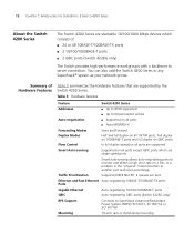
...100/1000BASE-T ports GBIC Auto-negotiating GBIC ports (Switch 4228G only) RPS Support Connects to any SuperStack® system as your network grows. 12 CHAPTER 1: INTRODUCING THE SUPERSTACK 3 SWITCH 4200 SERIES About the Switch 4200 Series The Switch 4200 Series are stackable 10/100/1000 Mbps ...all 10/100 ports. Table 3 Hardware features Feature Switch 4200 Series Addresses ■ Up to 8000 supported ■ Up to another port and react accordingly. You can also add the Switch 4200 Series to SuperStack Advanced Redundant Power System (ARPS) (3C16071, 3C16071A or 3C16071B) ...
...100/1000BASE-T ports GBIC Auto-negotiating GBIC ports (Switch 4228G only) RPS Support Connects to any SuperStack® system as your network grows. 12 CHAPTER 1: INTRODUCING THE SUPERSTACK 3 SWITCH 4200 SERIES About the Switch 4200 Series The Switch 4200 Series are stackable 10/100/1000 Mbps ...all 10/100 ports. Table 3 Hardware features Feature Switch 4200 Series Addresses ■ Up to 8000 supported ■ Up to another port and react accordingly. You can also add the Switch 4200 Series to SuperStack Advanced Redundant Power System (ARPS) (3C16071, 3C16071A or 3C16071B) ...
Getting Started Guide
Page 13
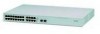
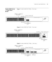
... 2 3 Alert 4 Unit 27 27 28 3C17304 Superstack 3 Switch 4228G 28 Alert LED 10/100/1000BASE-T ports GBIC ports About the Switch 4200 Series 13 Switch 4200 Series - Front View Detail Figure 1 Switch 4226T (3C17300) - front view 10BASE-T / 100BASE-TX RJ-45 Ports Unit LEDs Power / Self Test LED 1 13 2 14 3 ... Test 1 25 / Up 26 / Down 2 3 Alert 4 Unit Alert LED 10/100/1000BASE-T ports 3C17300 Superstack 3 Switch 4226T Figure 2 Switch 4250T (3C17302) - front view 10BASE-T / 100BASE-TX RJ-45 Ports Unit LEDs Power / Self Test LED 1 25 2 26 3 27 4 28 5 29 6 30 7 31 8 32 9 33...
... 2 3 Alert 4 Unit 27 27 28 3C17304 Superstack 3 Switch 4228G 28 Alert LED 10/100/1000BASE-T ports GBIC ports About the Switch 4200 Series 13 Switch 4200 Series - Front View Detail Figure 1 Switch 4226T (3C17300) - front view 10BASE-T / 100BASE-TX RJ-45 Ports Unit LEDs Power / Self Test LED 1 13 2 14 3 ... Test 1 25 / Up 26 / Down 2 3 Alert 4 Unit Alert LED 10/100/1000BASE-T ports 3C17300 Superstack 3 Switch 4226T Figure 2 Switch 4250T (3C17302) - front view 10BASE-T / 100BASE-TX RJ-45 Ports Unit LEDs Power / Self Test LED 1 25 2 26 3 27 4 28 5 29 6 30 7 31 8 32 9 33...

Getting Started Guide
Page 16
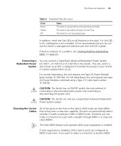
...Self Test). Green / Yellow A 10, 100 or 1000 Mbps link present but disabled. Yellow The Switch has failed its Power On Self Test. Alert LED Green flashing The Switch Alert LED has been configured via the CLI or Web Interface to be off (Default state). alternating .... 16 CHAPTER 1: INTRODUCING THE SUPERSTACK 3 SWITCH 4200 SERIES LED Color Indicates Green flashing Packets are being transmitted/received on the port. Off The Switch is not receiving power or there is present. Unit LEDs 1-4 Green When the Switch forms a stack with the Power Supply Unit. Yellow flashing Packets ...
...Self Test). Green / Yellow A 10, 100 or 1000 Mbps link present but disabled. Yellow The Switch has failed its Power On Self Test. Alert LED Green flashing The Switch Alert LED has been configured via the CLI or Web Interface to be off (Default state). alternating .... 16 CHAPTER 1: INTRODUCING THE SUPERSTACK 3 SWITCH 4200 SERIES LED Color Indicates Green flashing Packets are being transmitted/received on the port. Off The Switch is not receiving power or there is present. Unit LEDs 1-4 Green When the Switch forms a stack with the Power Supply Unit. Yellow flashing Packets ...
Getting Started Guide
Page 17
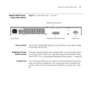
... set to any supply voltage in the range 90-240 VAC. Redundant Power To protect against internal power supply failure, you to a SuperStack Advanced Redundant Power System (RPS). See "Connecting a Redundant Power System" on page 25. About the Switch 4200 Series 17 Switch 4200 Series Figure 4 Switch 4200 Series - Rear View Detail Supply Data Warning Label Console (max...
... set to any supply voltage in the range 90-240 VAC. Redundant Power To protect against internal power supply failure, you to a SuperStack Advanced Redundant Power System (RPS). See "Connecting a Redundant Power System" on page 25. About the Switch 4200 Series 17 Switch 4200 Series Figure 4 Switch 4200 Series - Rear View Detail Supply Data Warning Label Console (max...
Getting Started Guide
Page 19
... oder Instandhaltungsarbeiten verrichten, lesen Sie die Sicherheitsanweisungen, die in Appendix A (Anhang A) in Appendix A of Each Other ■ The Power-up the Switch 4200 Series. VORSICHT: Sicherheitsinformationen. Before installing or removing any components from the Switch 4200 Series or carrying out any maintenance procedures, you need to install and set up Sequence ■ GBIC...
... oder Instandhaltungsarbeiten verrichten, lesen Sie die Sicherheitsanweisungen, die in Appendix A (Anhang A) in Appendix A of Each Other ■ The Power-up the Switch 4200 Series. VORSICHT: Sicherheitsinformationen. Before installing or removing any components from the Switch 4200 Series or carrying out any maintenance procedures, you need to install and set up Sequence ■ GBIC...
Getting Started Guide
Page 20
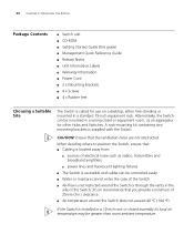
... Labels ■ Warranty Information ■ Power Cord ■ 2 x Mounting brackets ■ 4 x Screws ■ 4 x Rubber feet Choosing a Suitable Site The Switch is suited for other Hubs and Switches. If the Switch is supplied with the Switch. A rack-mounting kit containing two mounting brackets is installed in the side of the Switch. 3Com recommends that the ventilation holes are...
... Labels ■ Warranty Information ■ Power Cord ■ 2 x Mounting brackets ■ 4 x Screws ■ 4 x Rubber feet Choosing a Suitable Site The Switch is suited for other Hubs and Switches. If the Switch is supplied with the Switch. A rack-mounting kit containing two mounting brackets is installed in the side of the Switch. 3Com recommends that the ventilation holes are...
Getting Started Guide
Page 23
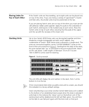
... 28 1 13 2 14 3 15 4 16 5 17 6 18 7 19 8 20 9 21 10 22 11 23 12 24 Power/ Self Test 1 25 / Up 26 / Down 2 3 Alert 4 Unit 3C17300 Superstack 3 Switch 4226T The unit LEDs will display the unit number in a single stack. In this instance the 'down ' on top of the existing stack will be disabled... pads to the bottom of an established stack except when the stack is already 4 units high. Starting from 1 at the bottom to 4 at the top. 3Com recommends that when you add a new unit to a stack, you are connected together via the 10/100/1000BASE-T ports on that port again until the...
... 28 1 13 2 14 3 15 4 16 5 17 6 18 7 19 8 20 9 21 10 22 11 23 12 24 Power/ Self Test 1 25 / Up 26 / Down 2 3 Alert 4 Unit 3C17300 Superstack 3 Switch 4226T The unit LEDs will display the unit number in a single stack. In this instance the 'down ' on top of the existing stack will be disabled... pads to the bottom of an established stack except when the stack is already 4 units high. Starting from 1 at the bottom to 4 at the top. 3Com recommends that when you add a new unit to a stack, you are connected together via the 10/100/1000BASE-T ports on that port again until the...
Getting Started Guide
Page 24
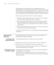
.... If however the unit being added takes the stack height above will renumber. ■ Removing a Switch 4200 Series unit from the middle of the Switch. 2 Plug the other Switches in a set sequence. The Switch powers-up the Switch. When removing a Switch from a stack, note the following sections describe how to "Solving Stack Formation Problems" on the remaining...
.... If however the unit being added takes the stack height above will renumber. ■ Removing a Switch 4200 Series unit from the middle of the Switch. 2 Plug the other Switches in a set sequence. The Switch powers-up the Switch. When removing a Switch from a stack, note the following sections describe how to "Solving Stack Formation Problems" on the remaining...
Getting Started Guide
Page 25
... disconnecting the power cord. Therefore you can connect a SuperStack Advanced Redundant Power System (3C16071, 3C16071A or 3C16071B) to another MDIX If a Unit LED is off, initialization is not complete. 3Com recommends that is they have a cross-over capability. Connecting a Redundant Power System You can make a connection to the Switch. the only method of the Switch 4200 Series...
... disconnecting the power cord. Therefore you can connect a SuperStack Advanced Redundant Power System (3C16071, 3C16071A or 3C16071B) to another MDIX If a Unit LED is off, initialization is not complete. 3Com recommends that is they have a cross-over capability. Connecting a Redundant Power System You can make a connection to the Switch. the only method of the Switch 4200 Series...
Getting Started Guide
Page 27
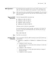
...power down the Switch. This section applies to Category 5 twisted-pair cable. ■ 1000BASE-LX GBIC transceiver GBIC transceivers are correct at the time of approved GBIC transceivers for the Switch on the 3Com Corporation World Wide Web site, enter this transceiver to connect the Switch directly to the SuperStack 3 Switch... 4228G only. Approved GBIC Transceivers The 3Com approved GBIC transceivers are: ■ ...
...power down the Switch. This section applies to Category 5 twisted-pair cable. ■ 1000BASE-LX GBIC transceiver GBIC transceivers are correct at the time of approved GBIC transceivers for the Switch on the 3Com Corporation World Wide Web site, enter this transceiver to connect the Switch directly to the SuperStack 3 Switch... 4228G only. Approved GBIC Transceivers The 3Com approved GBIC transceivers are: ■ ...
Getting Started Guide
Page 32
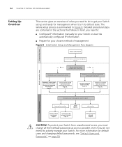
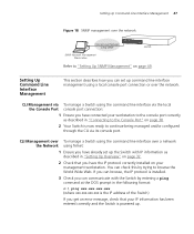
... gives an overview of management Figure 8 Initial Switch Setup and Management Flow diagram Power up and ready for your Switch set up the Switch. Detailed procedural steps are contained in Figure 8. How do you want to Manage your Switch? Connect to the Switch? Feature Management How do to a console port.... Plug and Play Setup Initial IP Information Setup IP information is summarised in the sections that follow. Page 33. Page 38. Use 3Com Network Supervisor (3NS). Connect to get your chosen method of what you need to do you need to: ■ Configure IP information...
... gives an overview of management Figure 8 Initial Switch Setup and Management Flow diagram Power up and ready for your Switch set up the Switch. Detailed procedural steps are contained in Figure 8. How do you want to Manage your Switch? Connect to the Switch? Feature Management How do to a console port.... Plug and Play Setup Initial IP Information Setup IP information is summarised in the sections that follow. Page 33. Page 38. Use 3Com Network Supervisor (3NS). Connect to get your chosen method of what you need to do you need to: ■ Configure IP information...
Getting Started Guide
Page 35
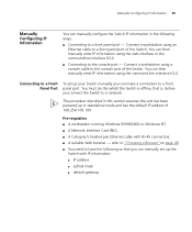
...IP address of 169.254.100.100. Connect a workstation using a console cable to a front panel port - You can manually set up the Switch with RJ-45 connectors. ■ A suitable Web browser - Connect a workstation using an Ethernet cable to a front panel port of the... have the following ways: ■ Connecting to the console port of the Switch. You can make a connection to the console port - You must do this section assumes the unit has been powered up your Switch manually you can then manually enter IP information using the command line interface (CLI). refer to...
...IP address of 169.254.100.100. Connect a workstation using a console cable to a front panel port - You can manually set up the Switch with RJ-45 connectors. ■ A suitable Web browser - Connect a workstation using an Ethernet cable to a front panel port of the... have the following ways: ■ Connecting to the console port of the Switch. You can make a connection to the console port - You must do this section assumes the unit has been powered up your Switch manually you can then manually enter IP information using the command line interface (CLI). refer to...
Getting Started Guide
Page 36
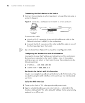
... to the following settings: ■ IP address - 169.254.100.99 ■ Subnet mask - 255.255.0.0 Setting Up the Switch with IP information. Using the Web Interface 1 Power-up the Switch with IP Information You are now ready to any other end of the cable to one of the Ethernet cable to... an offline unit. Do not interconnect the Switch to manually set up the Switch. This is automatically assigned to the Network ...
... to the following settings: ■ IP address - 169.254.100.99 ■ Subnet mask - 255.255.0.0 Setting Up the Switch with IP information. Using the Web Interface 1 Power-up the Switch with IP Information You are now ready to any other end of the cable to one of the Ethernet cable to... an offline unit. Do not interconnect the Switch to manually set up the Switch. This is automatically assigned to the Network ...
Getting Started Guide
Page 42
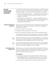
... on the Supervisor CD-ROM that accompanies your Switch to discover the automatically allocated IP information. 1 Connect your Switch to the network. 2 Power-up the Switch and wait for two minutes. 3 Launch 3Com Network Supervisor and run the Auto-discovery wizard. 3Com Network Supervisor will auto-discover the Switch and display the automatically allocated IP information assigned...
... on the Supervisor CD-ROM that accompanies your Switch to discover the automatically allocated IP information. 1 Connect your Switch to the network. 2 Power-up the Switch and wait for two minutes. 3 Launch 3Com Network Supervisor and run the Auto-discovery wizard. 3Com Network Supervisor will auto-discover the Switch and display the automatically allocated IP information assigned...
Getting Started Guide
Page 47
... command at the DOS prompt in "Setting Up Overview" on page 32. 2 Check that your management workstation. If you can browse, the IP protocol is powered up the Switch with IP information as described in "Connecting to browse the World Wide Web. CLI Management over To manage...line interface over a network the Network using a local console port connection or over the network Refer to "Setting Up SNMP Management" on page 38. 2 Your Switch is now ready to continue being managed and/or configured through the CLI via the local the Console Port console port connection: 1 Ensure you have...
... command at the DOS prompt in "Setting Up Overview" on page 32. 2 Check that your management workstation. If you can browse, the IP protocol is powered up the Switch with IP information as described in "Connecting to browse the World Wide Web. CLI Management over To manage...line interface over a network the Network using a local console port connection or over the network Refer to "Setting Up SNMP Management" on page 38. 2 Your Switch is now ready to continue being managed and/or configured through the CLI via the local the Console Port console port connection: 1 Ensure you have...
Getting Started Guide
Page 49
...the management workstation. ■ The management workstation is connected to the Switch using the web interface over an IP network: Over the Network 1 Check that you use the 3Com Network Supervisor application that is provided on the Switch are enabled on a browser by trying to browse the World Wide ...Management Protocol (SNMP) can use 3Com Network Supervisor it automatically loads the correct MIBs and necessary files onto your workstation. If you can browse, the IP protocol is powered up. 3 Open your web browser and enter the IP address of the Switch that you wish to provide ...
...the management workstation. ■ The management workstation is connected to the Switch using the web interface over an IP network: Over the Network 1 Check that you use the 3Com Network Supervisor application that is provided on the Switch are enabled on a browser by trying to browse the World Wide ...Management Protocol (SNMP) can use 3Com Network Supervisor it automatically loads the correct MIBs and necessary files onto your workstation. If you can browse, the IP protocol is powered up. 3 Open your web browser and enter the IP address of the Switch that you wish to provide ...

Getting Started Guide
Page 54
... of an internal problem. If the connection is secure and there is connected and yet the Status LED for advice. The Power LED does not light Check that : ■ The Switch and the device at the other end of the link (or cable) are connected securely. ■ The devices at both ...ends of the link are powered-up , the Power/Self Test LED lights yellow The Switch unit has failed its Power On Self Test (POST) because of cable is satisfactory ■ Auto-negotiation settings are being used (cross-over or...
... of an internal problem. If the connection is secure and there is connected and yet the Status LED for advice. The Power LED does not light Check that : ■ The Switch and the device at the other end of the link (or cable) are connected securely. ■ The devices at both ...ends of the link are powered-up , the Power/Self Test LED lights yellow The Switch unit has failed its Power On Self Test (POST) because of cable is satisfactory ■ Auto-negotiation settings are being used (cross-over or...

