Quick Installation Guide
Page 3
Installing the Battery Backup Unit 23 Tools and equipment required 24 Installation Overview 24 Installation Instructions 26 Replacing the Battery 32 www.3ware.com iii Table of Package 1 Other Documentation 2 Installation Considerations 2 What You Need: Tools and Equipment 4 Safety Factors 4 ... computer 15 To install the drives 16 Connecting Drive Activity LED Indicators 17 Finishing Up 21 Check Installation and Close the Case 21 Configure your RAID Arrays 21 Chapter 2. Installing an AMCC 3ware 9550SX RAID Controller 1 Before You Begin 1 Contents of Contents Chapter 1.
Installing the Battery Backup Unit 23 Tools and equipment required 24 Installation Overview 24 Installation Instructions 26 Replacing the Battery 32 www.3ware.com iii Table of Package 1 Other Documentation 2 Installation Considerations 2 What You Need: Tools and Equipment 4 Safety Factors 4 ... computer 15 To install the drives 16 Connecting Drive Activity LED Indicators 17 Finishing Up 21 Check Installation and Close the Case 21 Configure your RAID Arrays 21 Chapter 2. Installing an AMCC 3ware 9550SX RAID Controller 1 Before You Begin 1 Contents of Contents Chapter 1.
Quick Installation Guide
Page 16
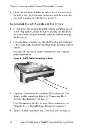
...Controller and plug it into the drive or drive carrier. SATA Cable Connecting to ensure proper installation. Installing an AMCC 3ware 9550SX RAID Controller 8 Check that the 3ware RAID controller's metal bracket covers the hole in the case and secure the bracket with the screw that the drives are...) Connect the drive activity LED connectors. For a discussion of an SATA cable not connected to "Check Installation and Close the Case" on page 21. 12 3ware 9550SX Serial ATA RAID Controller Quick Install Guide For details, see "Whether to Use the LED Status Connector" on page 17.
...Controller and plug it into the drive or drive carrier. SATA Cable Connecting to ensure proper installation. Installing an AMCC 3ware 9550SX RAID Controller 8 Check that the 3ware RAID controller's metal bracket covers the hole in the case and secure the bracket with the screw that the drives are...) Connect the drive activity LED connectors. For a discussion of an SATA cable not connected to "Check Installation and Close the Case" on page 21. 12 3ware 9550SX Serial ATA RAID Controller Quick Install Guide For details, see "Whether to Use the LED Status Connector" on page 17.

Quick Installation Guide
Page 25
... the Case 1 Verify that the cables do not interfere with the operation of cooling air. 2 Close the case and reconnect the power cables. www.3ware.com 21 Configure your RAID Arrays Turn to complete the hardware installation. Finishing Up Table 1: LED Indicator Pin Positions Controller 9550SX-16ML LED Header Pin Pair J7... cables to the controller and drives, complete the following steps to "Configuring Units" in the case or block the flow of any other components in 3ware 9550SX Serial ATA RAID Controller User Guide for information about configuring RAID arrays.
... the Case 1 Verify that the cables do not interfere with the operation of cooling air. 2 Close the case and reconnect the power cables. www.3ware.com 21 Configure your RAID Arrays Turn to complete the hardware installation. Finishing Up Table 1: LED Indicator Pin Positions Controller 9550SX-16ML LED Header Pin Pair J7... cables to the controller and drives, complete the following steps to "Configuring Units" in the case or block the flow of any other components in 3ware 9550SX Serial ATA RAID Controller User Guide for information about configuring RAID arrays.

Quick Installation Guide
Page 29
Points of connection on the half-height controller a) Holes for the clips b) BBU receptacle c) Hole for post Figure 20. Points of connection on the full-height controller www.3ware.com 25 Installation Overview a) Slots for the clips b) BBU receptacle c) Hole for post Figure 21.
Points of connection on the half-height controller a) Holes for the clips b) BBU receptacle c) Hole for post Figure 20. Points of connection on the full-height controller www.3ware.com 25 Installation Overview a) Slots for the clips b) BBU receptacle c) Hole for post Figure 21.